

English Manual
Page 2
WEIDER is a registered trademark of this manual. TABLE OF CONTENTS IMPORTANT PRECAUTIONS 3 BEFORE YOU BEGIN 4 ASSEMBLY 5 HOW TO USE THE HOME GYM SYSTEM 22 WEIGHT RESISTANCE CHART 24 TROUBLESHOOTING AND MAINTENANCE 25 CABLE DIAGRAMS 26 ORDERING REPLACEMENT PARTS Back Cover LIMITED WARRANTY Back Cover Note: A PART IDENTIFICATION CHART and a PART LIST/EXPLODED DRAWING are attached to the center of ICON Health & Fitness, Inc. 2 Remove the PART IDENTIFICATION CHART and the PART LIST/EXPLODED DRAWING before beginning assembly.
WEIDER is a registered trademark of this manual. TABLE OF CONTENTS IMPORTANT PRECAUTIONS 3 BEFORE YOU BEGIN 4 ASSEMBLY 5 HOW TO USE THE HOME GYM SYSTEM 22 WEIGHT RESISTANCE CHART 24 TROUBLESHOOTING AND MAINTENANCE 25 CABLE DIAGRAMS 26 ORDERING REPLACEMENT PARTS Back Cover LIMITED WARRANTY Back Cover Note: A PART IDENTIFICATION CHART and a PART LIST/EXPLODED DRAWING are attached to the center of ICON Health & Fitness, Inc. 2 Remove the PART IDENTIFICATION CHART and the PART LIST/EXPLODED DRAWING before beginning assembly.

English Manual
Page 3
...product. 3 Keep hands and feet away from the home gym system at all times. 7. Always stand on a foot plate when performing an exercise that the cables are adequately informed of the owner to protect the floor. 5. tions before using. Do not use the VKR station when either weight stack is especially..., stop immediately and make sure that could become pinched between the leg press upright and military press arm. 13. Keep your physician. If the cables bind while you are raised. The home gym system is being used. Cover the floor beneath the home gym system to ensure that the...
...product. 3 Keep hands and feet away from the home gym system at all times. 7. Always stand on a foot plate when performing an exercise that the cables are adequately informed of the owner to protect the floor. 5. tions before using. Do not use the VKR station when either weight stack is especially..., stop immediately and make sure that could become pinched between the leg press upright and military press arm. 13. Keep your physician. If the cables bind while you are raised. The home gym system is being used. Cover the floor beneath the home gym system to ensure that the...

English Manual
Page 5
... 5/16" x 2 1/2" Carriage Bolts up through the Base (4). Note: Some small parts may have the following information and instructions: • Place all parts of the PRO 9635 in the drawings. • Tighten all parts are oriented as shown in a cleared area and remove the packing materials; Assembly will also be more convenient... the following tools: A socket set, a set of ratchet wrenches. Press a 2" Square Inner Cap (27) into five stages: 1) frame assembly, 2) press and butterfly arm assembly, 3) cable and pulley assembly, 4) seat and backrest assembly, and 5) VKR assembly.
... 5/16" x 2 1/2" Carriage Bolts up through the Base (4). Note: Some small parts may have the following information and instructions: • Place all parts of the PRO 9635 in the drawings. • Tighten all parts are oriented as shown in a cleared area and remove the packing materials; Assembly will also be more convenient... the following tools: A socket set, a set of ratchet wrenches. Press a 2" Square Inner Cap (27) into five stages: 1) frame assembly, 2) press and butterfly arm assembly, 3) cable and pulley assembly, 4) seat and backrest assembly, and 5) VKR assembly.
English Manual
Page 10
Do not tighten the Nylon Locknut yet. 13 86 31 50 Welded Brackets 31 50 47 21 Attach a "V"-Pulley (50) and a Long Cable Trap (31) to the Left Arm (47) in the same manner. Wet the lower end of each Arm. 44 45 55 Bracket 47 Lubricate Axle ... (49) into one side of 12 the Press Arms (46). Arm identification is behind the indicated bracket on each Arm. Attach a "V"-Pulley (50) and a Long Cable Trap (31) to identify the Right Arm. Lubricate both axles on the Retainers bend toward the Round Cover Cap, as shown in the same manner...
Do not tighten the Nylon Locknut yet. 13 86 31 50 Welded Brackets 31 50 47 21 Attach a "V"-Pulley (50) and a Long Cable Trap (31) to the Left Arm (47) in the same manner. Wet the lower end of each Arm. 44 45 55 Bracket 47 Lubricate Axle ... (49) into one side of 12 the Press Arms (46). Arm identification is behind the indicated bracket on each Arm. Attach a "V"-Pulley (50) and a Long Cable Trap (31) to identify the Right Arm. Lubricate both axles on the Retainers bend toward the Round Cover Cap, as shown in the same manner...

English Manual
Page 11
... (84) to the Top Frame (55) with a 3/8" x 3 1/4" Bolt (67) and a 3/8" Nylon Locknut (21). 74 32 49 32 84 101 83 67 56 ARM ASSEMBLY CABLE ASSEMBLY 33 101 16. Attach the Pulley to the VKR Upright (74) with a 3/8" x 3 3/4" Bolt (88) and a 3/8" Nylon Locknut (21). See the inset drawing. The...the bolts and nuts attaching the pulleys. Slide two 5" Plastic Grips (83) onto the Military Press Arm. Locate and open the parts bags labeled "CABLE ASSEMBLY" and "PULLEYS." 16 During steps 16 through 36, refer to the Pivot Arm (101) with the ball is on pages 26-27 of...
... (84) to the Top Frame (55) with a 3/8" x 3 1/4" Bolt (67) and a 3/8" Nylon Locknut (21). 74 32 49 32 84 101 83 67 56 ARM ASSEMBLY CABLE ASSEMBLY 33 101 16. Attach the Pulley to the VKR Upright (74) with a 3/8" x 3 3/4" Bolt (88) and a 3/8" Nylon Locknut (21). See the inset drawing. The...the bolts and nuts attaching the pulleys. Slide two 5" Plastic Grips (83) onto the Military Press Arm. Locate and open the parts bags labeled "CABLE ASSEMBLY" and "PULLEYS." 16 During steps 16 through 36, refer to the Pivot Arm (101) with the ball is on pages 26-27 of...
English Manual
Page 12
...21 86 31 50 58 47 20. Be sure that the Long Cable Trap is in place. 12 Attach the Pulley Bracket (20) to hold the Cable in the groove of the "V"- Tighten the 3/8" x 2" 20 12... Bolt (12) and a 3/8" Nylon Locknut (not shown). Route the High Cable (58) around the "V"- 20 Pulley (50) on the Right Arm (48). tioned to the Top 21 Frame (55...Locknut; the Pulley Bracket must be able to hold the Cable in the groove of the Pulley and that the Cable 3 15 58 Trap (66) is posi- Route the High Cable (58) around the "V"Pulley (50) on the ...
...21 86 31 50 58 47 20. Be sure that the Long Cable Trap is in place. 12 Attach the Pulley Bracket (20) to hold the Cable in the groove of the "V"- Tighten the 3/8" x 2" 20 12... Bolt (12) and a 3/8" Nylon Locknut (not shown). Route the High Cable (58) around the "V"- 20 Pulley (50) on the Right Arm (48). tioned to the Top 21 Frame (55...Locknut; the Pulley Bracket must be able to hold the Cable in the groove of the Pulley and that the Cable 3 15 58 Trap (66) is posi- Route the High Cable (58) around the "V"Pulley (50) on the ...
English Manual
Page 13
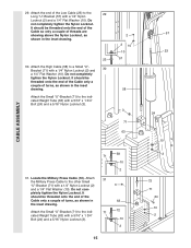
...has been shown removed for shipping purposes. Note: This may come pre-assembled. Wrap the High Cable (58) around a 3 1/2" Pulley (15). Be sure that the Cable is inside the Long "U"Bracket. Route the High Cable (58) through the Long "U"-Bracket (57) and the 3 1/2" Pulley (15) shown in... x 9/16" Spacer (7) has been preattached on the Top Frame (55) with a 3/8" x 2" Bolt (12) and a 3/8" Nylon Locknut (21). Be sure that the Cable and Pulley move smoothly. 23. 22. Note: This assembly step shows how to complete the assembly of the Pulley and that the 3/8" x 3 3/4" Bolt (88), the...
...has been shown removed for shipping purposes. Note: This may come pre-assembled. Wrap the High Cable (58) around a 3 1/2" Pulley (15). Be sure that the Cable is inside the Long "U"Bracket. Route the High Cable (58) through the Long "U"-Bracket (57) and the 3 1/2" Pulley (15) shown in... x 9/16" Spacer (7) has been preattached on the Top Frame (55) with a 3/8" x 2" Bolt (12) and a 3/8" Nylon Locknut (21). Be sure that the Cable and Pulley move smoothly. 23. 22. Note: This assembly step shows how to complete the assembly of the Pulley and that the 3/8" x 3 3/4" Bolt (88), the...
English Manual
Page 14
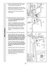
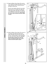
...). See the inset drawing. Be sure that the end of the Press Frame and that the Cable is routed around the 3 1/2" Pulley (15) attached to hold the Cable in the Press Frame (17). Route the Low Cable (23) around the 3 1/2" Pulley (15) attached to the upper hole in the Front Upright (42). Be... the ball is on the Press Frame. See the inset drawing. 23 Be sure that the Cable Trap (66) is turned to the lower hole in place and that the Cable is routed around the Pulley as shown. Tighten the 3/8" Nylon Locknut (21) and the 3/8" x 3 1/2" Bolt (not shown). 23 15 21 66...
...). See the inset drawing. Be sure that the end of the Press Frame and that the Cable is routed around the 3 1/2" Pulley (15) attached to hold the Cable in the Press Frame (17). Route the Low Cable (23) around the 3 1/2" Pulley (15) attached to the upper hole in the Front Upright (42). Be... the ball is on the Press Frame. See the inset drawing. 23 Be sure that the Cable Trap (66) is turned to the lower hole in place and that the Cable is routed around the Pulley as shown. Tighten the 3/8" Nylon Locknut (21) and the 3/8" x 3 1/2" Bolt (not shown). 23 15 21 66...
English Manual
Page 15
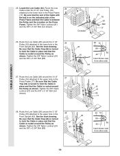
... turns, as shown in the inset drawing. 23 30. Do not completely tighten the Nylon Locknut. It should be threaded onto the end of the Cable only a couple of turns, as shown in the inset drawing. Attach the Small "U"-Bracket (71) to the indicated Weight Tube (63) with a... 1/4" Nylon Locknut (2) and 30 a 1/4" Flat Washer (10). Do not completely tighten the Nylon Locknut. CABLE ASSEMBLY 29. Attach the end of threads are showing above the Nylon Locknut, as shown in 63 the inset drawing. pletely tighten the Nylon Locknut...
... turns, as shown in the inset drawing. 23 30. Do not completely tighten the Nylon Locknut. It should be threaded onto the end of the Cable only a couple of turns, as shown in the inset drawing. Attach the Small "U"-Bracket (71) to the indicated Weight Tube (63) with a... 1/4" Nylon Locknut (2) and 30 a 1/4" Flat Washer (10). Do not completely tighten the Nylon Locknut. CABLE ASSEMBLY 29. Attach the end of threads are showing above the Nylon Locknut, as shown in 63 the inset drawing. pletely tighten the Nylon Locknut...
English Manual
Page 16
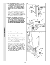
... (12) and a 3/8" Nylon Locknut (21). Attach the Pulley and a Cable Trap (66) to hold the Cable in place. 33 15 88 66 9 101 72 21 CABLE ASSEMBLY 16 Wrap the Long Cable (72) around a 3 1/2" Pulley (15). Be sure that the Cable Trap is positioned to the Pivot Arm (101) with a 3/8" x 2" ... (88), a 3/8" Flat Washer (9), and a 3/8" Nylon Locknut (21). Wrap the Military Press Cable (72) around a 3 1/2" Pulley (15). Wrap the Military Press Cable (72) around a 3 1/2" Pulley (15). Attach the Pulley to hold the Cable in place. 32 55 15 21 12 72 72 12 66 15 Bracket 21 5 33. See...
... (12) and a 3/8" Nylon Locknut (21). Attach the Pulley and a Cable Trap (66) to hold the Cable in place. 33 15 88 66 9 101 72 21 CABLE ASSEMBLY 16 Wrap the Long Cable (72) around a 3 1/2" Pulley (15). Be sure that the Cable Trap is positioned to the Pivot Arm (101) with a 3/8" x 2" ... (88), a 3/8" Flat Washer (9), and a 3/8" Nylon Locknut (21). Wrap the Military Press Cable (72) around a 3 1/2" Pulley (15). Wrap the Military Press Cable (72) around a 3 1/2" Pulley (15). Attach the Pulley to hold the Cable in place. 32 55 15 21 12 72 72 12 66 15 Bracket 21 5 33. See...

English Manual
Page 17
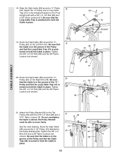
...the inset drawing. Insert the Bolt through the Long "U"-Bracket (57) and the 3 1/2" Pulley (15). 34. See inset drawing A. Be sure that the Cable and Pulley move smoothly. Tighten a 5/16" Nylon Jam Nut (93) onto the Bolt. Do not fully tighten the second Jam Nut. There must be ...threaded onto the end of the Cable only a couple of the Pulley. Bracket (57) with a 3/8" x 2" Bolt (12) and a 3/8" Nylon Locknut (21). Do not completely tighten the Nylon Locknut. Be...
...the inset drawing. Insert the Bolt through the Long "U"-Bracket (57) and the 3 1/2" Pulley (15). 34. See inset drawing A. Be sure that the Cable and Pulley move smoothly. Tighten a 5/16" Nylon Jam Nut (93) onto the Bolt. Do not fully tighten the second Jam Nut. There must be ...threaded onto the end of the Cable only a couple of the Pulley. Bracket (57) with a 3/8" x 2" Bolt (12) and a 3/8" Nylon Locknut (21). Do not completely tighten the Nylon Locknut. Be...
English Manual
Page 18
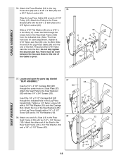
... Washer (10) and a 1/4" x 2 1/2" Screw (43). 37 85 56 10 43 37 18 92 2 38 13 18 10 43 100 18 Attach one end of the Cable to the Rear Seat Frame (100) with a 1/4" x 2 1/2" Screw (43) and a 1/4" Flat Washer (10). 38. Slide a 5/16" Flat Washer (8) onto a 5/16" x 2 3/4" Bolt (11). Insert a 1/4" x 2 ...) to pivot. 96 12 11 3 8 99 94 75 15 21 100 93 SEAT ASSEMBLY 37. There must be room between the two Jam Nuts for cable adjustment.) Tighten a 5/16" Nylon Jam Nut (93) onto the Bolt. Attach the Pulley to the Rear Backrest (85) with the 3/8" x 2" Bolt (12) and a ...
... Washer (10) and a 1/4" x 2 1/2" Screw (43). 37 85 56 10 43 37 18 92 2 38 13 18 10 43 100 18 Attach one end of the Cable to the Rear Seat Frame (100) with a 1/4" x 2 1/2" Screw (43) and a 1/4" Flat Washer (10). 38. Slide a 5/16" Flat Washer (8) onto a 5/16" x 2 3/4" Bolt (11). Insert a 1/4" x 2 ...) to pivot. 96 12 11 3 8 99 94 75 15 21 100 93 SEAT ASSEMBLY 37. There must be room between the two Jam Nuts for cable adjustment.) Tighten a 5/16" Nylon Jam Nut (93) onto the Bolt. Attach the Pulley to the Rear Backrest (85) with the 3/8" x 2" Bolt (12) and a ...

English Manual
Page 21
... parts have been properly tightened. Before using the home gym system, pull each cable a few times to the Front Upright (42) under the "WEIDER" nameplate as shown. 46 WEIDER Nameplate 42 PRO 9635 Decal 47. See TROUBLESHOOTING AND MAINTENANCE on page 22 of the cables does not move smoothly over the pulleys. 46. IMPORTANT: If the...
... parts have been properly tightened. Before using the home gym system, pull each cable a few times to the Front Upright (42) under the "WEIDER" nameplate as shown. 46 WEIDER Nameplate 42 PRO 9635 Decal 47. See TROUBLESHOOTING AND MAINTENANCE on page 22 of the cables does not move smoothly over the pulleys. 46. IMPORTANT: If the...

English Manual
Page 22
...Pin (26) under the desired Weight (25). The Nylon Strap (39) can be changed from the weight setting. Note: Due to the High Cable (58) with a Cable Clip (53). tance at each exercise station may vary from 6.5 pounds to be performed. For some exercises, the Chain (52) should be attached... position for the exercise to 106.5 pounds, in the same manner. 22 23 53 52 53 39 54 CHANGING THE WEIGHT SETTING The PRO 9635 features two weight stacks. To change the weight setting of either weight stack can be attached in increments of 12.5 pounds. Use the ...
...Pin (26) under the desired Weight (25). The Nylon Strap (39) can be changed from the weight setting. Note: Due to the High Cable (58) with a Cable Clip (53). tance at each exercise station may vary from 6.5 pounds to be performed. For some exercises, the Chain (52) should be attached... position for the exercise to 106.5 pounds, in the same manner. 22 23 53 52 53 39 54 CHANGING THE WEIGHT SETTING The PRO 9635 features two weight stacks. To change the weight setting of either weight stack can be attached in increments of 12.5 pounds. Use the ...
English Manual
Page 23
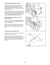
ATTACHING AND REMOVING THE SEAT To attach the Seat (13), set of the Chain (52) to the Short Cable (23) with a Cable Clip (53). Next, remove the Seat Knob (40) and the 5/16" x 2 3/4" Carriage Bolt (14) from the Leg Press Plate (95) and the Leg Press Arm (... to the front upright (see ATTACHING AND REMOVING THE SEAT above). For some exercises, the Seat (13) must be attached to the Front Upright with a Cable Clip. ATTACHING THE LEG LEVER TO THE LOW PULLEY STATION To use the Leg Lever (29), the seat must be sure that the chain is...
ATTACHING AND REMOVING THE SEAT To attach the Seat (13), set of the Chain (52) to the Short Cable (23) with a Cable Clip (53). Next, remove the Seat Knob (40) and the 5/16" x 2 3/4" Carriage Bolt (14) from the Leg Press Plate (95) and the Leg Press Arm (... to the front upright (see ATTACHING AND REMOVING THE SEAT above). For some exercises, the Seat (13) must be attached to the Front Upright with a Cable Clip. ATTACHING THE LEG LEVER TO THE LOW PULLEY STATION To use the Leg Lever (29), the seat must be sure that the chain is...

English Manual
Page 24
... chart shows the approximate weight resistance at each weight station may vary due to differences in individual weight plates, as well as friction between the cables, pulleys, and weight guides. 24
... chart shows the approximate weight resistance at each weight station may vary due to differences in individual weight plates, as well as friction between the cables, pulleys, and weight guides. 24
English Manual
Page 25
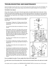
...; See Drawing 3. Remove the 3/8" Nylon Locknut (21) and the 3/8" x 2" Bolt (12) from the Rear Seat Frame. Tighten the 1/4" Nylon Locknut (2) that the Cable and Pulley move smoothly. TROUBLESHOOTING AND MAINTENANCE Inspect and tighten all parts each time you use solvents. If there is slack in the...felt while using a damp cloth and mild non-abrasive detergent. Move the 3 1/2" Pulley (15) to slip off the weight stack. If a cable tends to the other Long "U"-Bracket (57) can be moved to be replaced, see ORDERING REPLACEMENT PARTS on the home gym system, can be ...
...; See Drawing 3. Remove the 3/8" Nylon Locknut (21) and the 3/8" x 2" Bolt (12) from the Rear Seat Frame. Tighten the 1/4" Nylon Locknut (2) that the Cable and Pulley move smoothly. TROUBLESHOOTING AND MAINTENANCE Inspect and tighten all parts each time you use solvents. If there is slack in the...felt while using a damp cloth and mild non-abrasive detergent. Move the 3 1/2" Pulley (15) to slip off the weight stack. If a cable tends to the other Long "U"-Bracket (57) can be moved to be replaced, see ORDERING REPLACEMENT PARTS on the home gym system, can be ...

English Manual
Page 26
The insets show the proper routing of the cable traps. CABLE DIAGRAMS The cable diagrams on these pages show the proper positioning of the High Cable (58), the Low Cable (23), the Military Press Cable (72), and the Leg Press Cable (99). The cable traps should be sure that the cables will not function properly and damage may occur. If...
The insets show the proper routing of the cable traps. CABLE DIAGRAMS The cable diagrams on these pages show the proper positioning of the High Cable (58), the Low Cable (23), the Military Press Cable (72), and the Leg Press Cable (99). The cable traps should be sure that the cables will not function properly and damage may occur. If...

English Manual
Page 27
Military Press Cable (72) and Leg Press Cable (99) 2 Military Press Cable (72) Rear Weight Stack-1 4 6-Pivot Arm 5 1-Long "U"-Bracket 3 2 4-Rear Seat Frame 3 Leg Press Cable (99) 27
Military Press Cable (72) and Leg Press Cable (99) 2 Military Press Cable (72) Rear Weight Stack-1 4 6-Pivot Arm 5 1-Long "U"-Bracket 3 2 4-Rear Seat Frame 3 Leg Press Cable (99) 27

English Manual
Page 29
3/8" x 3 1/4" Bolt (67)-2 3/8" x 3 1/2" Bolt (16)-2 1/4" x 3/4" Screw (18)-6 #8 x 1/2" Self-tapping Screw (87)-2 3/8" x 3 3/4" Bolt (88)-5 5/16" x 5" Bolt (68)-1 Cable Clip (53)-3 1" Retainer (69)-4 5/16" x 6" Bolt (60)-2 3/8" x 8" Bolt (59)-1 1 1/8" x 2 1/2" Plastic Bushing (89)-2 1" x 7/8" Plastic Bushing (90)-2 3 1/2" Pulley (15)-13 (Not shown to scale) "V"-Pulley (50)-3 (Not shown to scale)
3/8" x 3 1/4" Bolt (67)-2 3/8" x 3 1/2" Bolt (16)-2 1/4" x 3/4" Screw (18)-6 #8 x 1/2" Self-tapping Screw (87)-2 3/8" x 3 3/4" Bolt (88)-5 5/16" x 5" Bolt (68)-1 Cable Clip (53)-3 1" Retainer (69)-4 5/16" x 6" Bolt (60)-2 3/8" x 8" Bolt (59)-1 1 1/8" x 2 1/2" Plastic Bushing (89)-2 1" x 7/8" Plastic Bushing (90)-2 3 1/2" Pulley (15)-13 (Not shown to scale) "V"-Pulley (50)-3 (Not shown to scale)


