
English Manual
Page 1
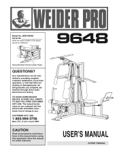
Serial Number Decal (Under Seat) QUESTIONS? The trained technicians on our customer hot line will guarantee you . USERÕS MANUAL PATENT PENDING As a manufacturer, we are missing or damaged parts, we will provide immediate assistance, free of charge to providing complete customer satisfaction. MST CAUTION Read all precautions and instructions in the space above for future reference. Write the serial number in this manual before using this manual for reference. TO AVOID UNNECESSARY DELAYS, PLEASE CALL DIRECT TO OUR TOLL-FREE CUSTOMER HOT LINE. Save this equipment....
Serial Number Decal (Under Seat) QUESTIONS? The trained technicians on our customer hot line will guarantee you . USERÕS MANUAL PATENT PENDING As a manufacturer, we are missing or damaged parts, we will provide immediate assistance, free of charge to providing complete customer satisfaction. MST CAUTION Read all precautions and instructions in the space above for future reference. Write the serial number in this manual before using this manual for reference. TO AVOID UNNECESSARY DELAYS, PLEASE CALL DIRECT TO OUR TOLL-FREE CUSTOMER HOT LINE. Save this equipment....
English Manual
Page 2
... 26 ORDERING REPLACEMENT PARTS Back Cover Note: A PART IDENTIFICATION CHART and a PART LIST/EXPLODED DRAWING are attached to the center of its authorized service centers. WEIDER is limited to the original purchaser.
... 26 ORDERING REPLACEMENT PARTS Back Cover Note: A PART IDENTIFICATION CHART and a PART LIST/EXPLODED DRAWING are attached to the center of its authorized service centers. WEIDER is limited to the original purchaser.
English Manual
Page 3
do not use the home gym system in the accompanying literature before using the home gym system. 4. Read all instructions in this manual and in an commercial, rental, or institutional setting. 3. Your hand could cause the home gym system to ensure that does not use only. The weights will fall with pre-existing health problems. Read all times. Always stand on a foot plate when performing an exercise that the cables remain on the pulleys at all instructions before using . Keep hands and feet away from the leg press upright when the military press arm is being used. Make ...
do not use the home gym system in the accompanying literature before using the home gym system. 4. Read all instructions in this manual and in an commercial, rental, or institutional setting. 3. Your hand could cause the home gym system to ensure that does not use only. The weights will fall with pre-existing health problems. Read all times. Always stand on a foot plate when performing an exercise that the cables remain on the pulleys at all instructions before using . Keep hands and feet away from the leg press upright when the military press arm is being used. Make ...
English Manual
Page 4
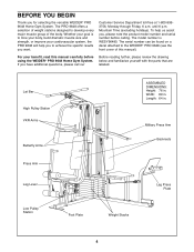
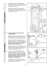
...muscle size and strength, or improve your cardiovascular system, the PRO 9648 will help us assist you for selecting the versatile WEIDER¨ PRO 9648 Home Gym System. The serial number can be found on a decal attached to the WEIDER¨ PRO 9648 (see the front cover of this manual carefully before calling... the parts that are labeled. BEFORE YOU BEGIN Thank you , please note the product model number and serial number before using the WEIDER¨ PRO 9648 Home Gym System. Lat Bar High Pulley Station VKR Arms Butterfly Arms ASSEMBLED DIMENSIONS: Height: 76 in . Width: 89 in. Whether...
...muscle size and strength, or improve your cardiovascular system, the PRO 9648 will help us assist you for selecting the versatile WEIDER¨ PRO 9648 Home Gym System. The serial number can be found on a decal attached to the WEIDER¨ PRO 9648 (see the front cover of this manual carefully before calling... the parts that are labeled. BEFORE YOU BEGIN Thank you , please note the product model number and serial number before using the WEIDER¨ PRO 9648 Home Gym System. Lat Bar High Pulley Station VKR Arms Butterfly Arms ASSEMBLED DIMENSIONS: Height: 76 in . Width: 89 in. Whether...
English Manual
Page 5
... hardware for each stage is packaged separately. ¥ Wait until assembly is completed. ¥ The assembly is not in the center of the PRO 9648 in a cleared area and remove the packing materials; Locate and open the parts bag labeled for shipping. Insert six 5/16Ó x 2 ...socket set, a set of open-end or closed-end wrenches, or a set of ratchet wrenches. Before beginning assembly, be more convenient if you assemble the PRO 9648 be sure that you assemble them, unless instructed to the Stabilizer (5) with two 5/16Ó x 2 3/4Ó Bolts (11), two 5/16Ó Flat...
... hardware for each stage is packaged separately. ¥ Wait until assembly is completed. ¥ The assembly is not in the center of the PRO 9648 in a cleared area and remove the packing materials; Locate and open the parts bag labeled for shipping. Insert six 5/16Ó x 2 ...socket set, a set of open-end or closed-end wrenches, or a set of ratchet wrenches. Before beginning assembly, be more convenient if you assemble the PRO 9648 be sure that you assemble them, unless instructed to the Stabilizer (5) with two 5/16Ó x 2 3/4Ó Bolts (11), two 5/16Ó Flat...
English Manual
Page 6
Do not tighten the Nylon Locknuts yet. Slide the VKR Upright (74) and the Leg Press Upright (56) onto the indicated 5/16Ó x 2 1/2Ó Carriage Bolts (1) in the Base (4). 3 Hand-tighten a 5/16Ó Nylon Locknut (3) onto each Carriage Bolt. Press two 2Ó Square Inner Caps (27) into the VKR Upright (74). The high side of Brackets 56 5 1 1 3. Hand-tighten four 5/16Ó Nylon Locknuts (3) onto the Carriage Bolts. Press a 2Ó Square Inner Cap into the Leg Press Upright (56). Attach the Rubber Bumper (91) to the Leg Press Upright (56) with the #8 x ...
Do not tighten the Nylon Locknuts yet. Slide the VKR Upright (74) and the Leg Press Upright (56) onto the indicated 5/16Ó x 2 1/2Ó Carriage Bolts (1) in the Base (4). 3 Hand-tighten a 5/16Ó Nylon Locknut (3) onto each Carriage Bolt. Press two 2Ó Square Inner Caps (27) into the VKR Upright (74). The high side of Brackets 56 5 1 1 3. Hand-tighten four 5/16Ó Nylon Locknuts (3) onto the Carriage Bolts. Press a 2Ó Square Inner Cap into the Leg Press Upright (56). Attach the Rubber Bumper (91) to the Leg Press Upright (56) with the #8 x ...
English Manual
Page 7
Press two 1Ó Round Inner Caps (49) into each end of the crossbar on the same side of each set of Weights. Tighten all on the Top Frame. Attach the Top Frame (55) to the Leg Press Upright (56) with two 5/16Ó x 2 3/4Ó Bolts (11), two 5/16Ó Flat Washers (8), and two 5/16Ó Nylon Locknuts (3). 55 11 49 8 44 3 44 Crossbar 3 56 42 74 FRAME ASSEMBLY 5. Stack eight Weights (25) onto each stack of Weight Bumpers (19). 4. Set two Weight Bumpers (19) on the bracket on the Stabilizer (5). Set two Weight Bumpers (19) on the bracket on the ...
Press two 1Ó Round Inner Caps (49) into each end of the crossbar on the same side of each set of Weights. Tighten all on the Top Frame. Attach the Top Frame (55) to the Leg Press Upright (56) with two 5/16Ó x 2 3/4Ó Bolts (11), two 5/16Ó Flat Washers (8), and two 5/16Ó Nylon Locknuts (3). 55 11 49 8 44 3 44 Crossbar 3 56 42 74 FRAME ASSEMBLY 5. Stack eight Weights (25) onto each stack of Weight Bumpers (19). 4. Set two Weight Bumpers (19) on the bracket on the Stabilizer (5). Set two Weight Bumpers (19) on the bracket on the ...
English Manual
Page 8
Lubricate the inside of a Weight Tube (63). Insert both Short Weight Guides (73) into the front stack of Weights. Be sure that the holes in the other Weight Tube (63). Press a Weight Tube Bumper (64) into the stack of Weights (25). Be sure that the pin on the Weight Tube is sit- Set the Top Weight onto the rear stack of Weights (25). 7. Be sure that the pin on the Weight Tube is sitting in the pin grooves in the Weight Guides are at the top, as shown. 65 Pin 63 62 Lubricate 64 Pin Grooves FRAME ASSEMBLY 25 8. Be sure that the holes in the top 73 ...
Lubricate the inside of a Weight Tube (63). Insert both Short Weight Guides (73) into the front stack of Weights. Be sure that the holes in the other Weight Tube (63). Press a Weight Tube Bumper (64) into the stack of Weights (25). Be sure that the pin on the Weight Tube is sit- Set the Top Weight onto the rear stack of Weights (25). 7. Be sure that the pin on the Weight Tube is sitting in the pin grooves in the Weight Guides are at the top, as shown. 65 Pin 63 62 Lubricate 64 Pin Grooves FRAME ASSEMBLY 25 8. Be sure that the holes in the top 73 ...
English Manual
Page 9
9. Align the welded tubes on the Leg Press Plate (95) with a 5/16Ó x 6Ó Bolt (60), two 1/2Ó x 3/4Ó Spacers (61), and a 5/16Ó Nylon Locknut (3). 9 61 60 73 3 61 60 3 55 62 FRAME ASSEMBLY ARM ASSEMBLY 10. The Plastic Bushings should fit on this side 59ÑLubricate 21 Welded Spacers 90 Lubricate the 3/8Ó x 8Ó Bolt (59). Attach the upper ends of the Stabilizer (5). Locate and open the parts bag labeled 10 ÒARM ASSEMBLY.Ó Be sure there is a Bushing (98) in each side of the Long Weight Guides (62) to the Stabilizer (5) ...
9. Align the welded tubes on the Leg Press Plate (95) with a 5/16Ó x 6Ó Bolt (60), two 1/2Ó x 3/4Ó Spacers (61), and a 5/16Ó Nylon Locknut (3). 9 61 60 73 3 61 60 3 55 62 FRAME ASSEMBLY ARM ASSEMBLY 10. The Plastic Bushings should fit on this side 59ÑLubricate 21 Welded Spacers 90 Lubricate the 3/8Ó x 8Ó Bolt (59). Attach the upper ends of the Stabilizer (5). Locate and open the parts bag labeled 10 ÒARM ASSEMBLY.Ó Be sure there is a Bushing (98) in each side of the Long Weight Guides (62) to the Stabilizer (5) ...

English Manual
Page 10
Be sure that the upper end of the Right Arm is very important for step 14. Note the position of 12 the Press Arms (46). refer to step 13 to one of the welded bracket on the Retainers bend toward the Round Cover Cap, as shown in the same manner. 46 3 17 13. Identify the Right Arm (48) and the Left Arm (47). Press a 1Ó Round Inner Cap (49) into one side of each Arm with a 3/8Ó x 2 1/2Ó Bolt (86) and a 3/8Ó Nylon Locknut (21). Lubricate both axles on the Top Frame (55). Be sure that 48 the teeth on each Arm. 44 45 55 Bracket 47 ...
Be sure that the upper end of the Right Arm is very important for step 14. Note the position of 12 the Press Arms (46). refer to step 13 to one of the welded bracket on the Retainers bend toward the Round Cover Cap, as shown in the same manner. 46 3 17 13. Identify the Right Arm (48) and the Left Arm (47). Press a 1Ó Round Inner Cap (49) into one side of each Arm with a 3/8Ó x 2 1/2Ó Bolt (86) and a 3/8Ó Nylon Locknut (21). Lubricate both axles on the Top Frame (55). Be sure that 48 the teeth on each Arm. 44 45 55 Bracket 47 ...
English Manual
Page 11
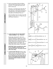
Attach the Military 15 Press Arm (84) to verify proper cable routing. IMPORTANT: While assembling the cables, do not overtighten the bolts and nuts attaching the pulleys. 15. Press two 1 1/2Ó Square Inner Caps (32) into 21 the Military Press Arm. Locate the High Cable (58). Identify the four Cables by comparing the lengths and ends of the Military Press Arm (84). Before beginning this manual to the Pivot Arm (101) with a 3/8Ó x 3 1/4Ó Bolt (67) and a 3/8Ó Nylon Locknut (21). 74 32 49 32 101 84 83 67 56 ARM ASSEMBLY CABLE ASSEMBLY 33 ...
Attach the Military 15 Press Arm (84) to verify proper cable routing. IMPORTANT: While assembling the cables, do not overtighten the bolts and nuts attaching the pulleys. 15. Press two 1 1/2Ó Square Inner Caps (32) into 21 the Military Press Arm. Locate the High Cable (58). Identify the four Cables by comparing the lengths and ends of the Military Press Arm (84). Before beginning this manual to the Pivot Arm (101) with a 3/8Ó x 3 1/4Ó Bolt (67) and a 3/8Ó Nylon Locknut (21). 74 32 49 32 101 84 83 67 56 ARM ASSEMBLY CABLE ASSEMBLY 33 ...

English Manual
Page 12
Wrap the High Cable (58) around the 3 1/2Ó Pulley (15) attached to hold the Cable in place. Pulley and that the Long Cable Trap (31) is in place. Tighten the 3/8Ó x 2 1/2Ó Bolt (86) and the 3/8Ó Nylon Locknut (not shown). 58 31 86 50 48 CABLE ASSEMBLY 21. the Pulley Bracket must be able to hold the Cable in the groove of the ÒVÓ- See the inset drawing. Route the High Cable 55 66 (58) around a ÒVÓ-Pulley 18 (50). Be sure that the Cable is in the groove of the Pulley and that 19 the Cable is turned to the Pulley Bracket (20...
Wrap the High Cable (58) around the 3 1/2Ó Pulley (15) attached to hold the Cable in place. Pulley and that the Long Cable Trap (31) is in place. Tighten the 3/8Ó x 2 1/2Ó Bolt (86) and the 3/8Ó Nylon Locknut (not shown). 58 31 86 50 48 CABLE ASSEMBLY 21. the Pulley Bracket must be able to hold the Cable in the groove of the ÒVÓ- See the inset drawing. Route the High Cable 55 66 (58) around a ÒVÓ-Pulley 18 (50). Be sure that the Cable is in the groove of the Pulley and that 19 the Cable is turned to the Pulley Bracket (20...

English Manual
Page 13
Attach a 3 1/2Ó Pulley (15) and a Cable Trap (66) to the upper hole in the groove of the 3 1/2Ó Low Pulley (76) for part identification. Be sure that the Cable is in a Long ÒUÓ-Bracket (57) with the 5/8Ó x 9/16Ó Spacer (7) between the Pulley and the Press Frame (17). The Bolt has been shown removed for shipping purposes. The 5/8Ó x 9/16Ó Spacer (7) has been preattached on the Top Frame (55) with a 3/8Ó x 2Ó Bolt (12) and a 3/8Ó Nylon Locknut (21). Be sure that the Cable and Pulley move smoothly. 22 66 21 57 23 55...
Attach a 3 1/2Ó Pulley (15) and a Cable Trap (66) to the upper hole in the groove of the 3 1/2Ó Low Pulley (76) for part identification. Be sure that the Cable is in a Long ÒUÓ-Bracket (57) with the 5/8Ó x 9/16Ó Spacer (7) between the Pulley and the Press Frame (17). The Bolt has been shown removed for shipping purposes. The 5/8Ó x 9/16Ó Spacer (7) has been preattached on the Top Frame (55) with a 3/8Ó x 2Ó Bolt (12) and a 3/8Ó Nylon Locknut (21). Be sure that the Cable and Pulley move smoothly. 22 66 21 57 23 55...

English Manual
Page 14
Locate the Low Cable (23). Crossbar 21 76 23 Ball 17 26. Tighten the 3/8Ó Nylon Locknut (21) 21 and the 3/8Ó x 3 3/4Ó Bolt (88). 23 15 88 66 42 Inset shows view from other side 14 See the inset drawing. Tighten the 3/8Ó Nylon Locknut (21) and the 3/8Ó x 3 1/2Ó Bolt (not shown). 23 15 21 66 17 28. Route the Low 25 Cable under the 3 1/2Ó Low Pulley (76) attached to the lower hole in place and that the Cable Trap (66) is routed around the Pulley as shown. Be sure that the Cable is turned to hold the Cable in the Press Frame ...
Locate the Low Cable (23). Crossbar 21 76 23 Ball 17 26. Tighten the 3/8Ó Nylon Locknut (21) 21 and the 3/8Ó x 3 3/4Ó Bolt (88). 23 15 88 66 42 Inset shows view from other side 14 See the inset drawing. Tighten the 3/8Ó Nylon Locknut (21) and the 3/8Ó x 3 1/2Ó Bolt (not shown). 23 15 21 66 17 28. Route the Low 25 Cable under the 3 1/2Ó Low Pulley (76) attached to the lower hole in place and that the Cable Trap (66) is routed around the Pulley as shown. Be sure that the Cable is turned to hold the Cable in the Press Frame ...

English Manual
Page 15
Do not completely tighten the Nylon Locknut. Do not completely tighten the Nylon Locknut. It should be threaded onto the end of the Cable only a couple of turns, as shown in 63 the inset drawing. It should be threaded onto the end of the Cable only a couple of turns, as shown in the inset drawing. CABLE ASSEMBLY 29. Attach the Small ÒUÓ-Bracket (71) to the indicated Weight Tube (63) with a 1/4Ó Nylon Locknut (2) 3 and a 1/4Ó Flat Washer (10). Attach 31 the Military Press Cable to the indi- 71 72 cated Weight Tube (63) with a 1/4Ó ...
Do not completely tighten the Nylon Locknut. Do not completely tighten the Nylon Locknut. It should be threaded onto the end of the Cable only a couple of turns, as shown in 63 the inset drawing. It should be threaded onto the end of the Cable only a couple of turns, as shown in the inset drawing. CABLE ASSEMBLY 29. Attach the Small ÒUÓ-Bracket (71) to the indicated Weight Tube (63) with a 1/4Ó Nylon Locknut (2) 3 and a 1/4Ó Flat Washer (10). Attach 31 the Military Press Cable to the indi- 71 72 cated Weight Tube (63) with a 1/4Ó ...

English Manual
Page 16
Wrap the Long Cable (72) around a 3 1/2Ó Pulley (15). Attach the Pulley and a Cable Trap (66) to the Top Frame (55) with the 3/8Ó x 3 3/4Ó Bolt (88), a 3/8Ó Flat Washer (9), and a 3/8Ó Nylon Locknut (21). See the inset drawing. Be sure that the Nylon Locknut is on the Stabilizer (5) with a 3/8Ó x 2Ó Bolt (12) and a 3/8Ó Nylon Locknut (21). Attach the Pulley to the Pivot Arm (101) with a 3/8Ó x 2Ó Bolt (12) and a 3/8Ó Nylon Locknut (21). Be sure that the Cable Trap is turned to hold the Cable in place. 33 15 88 66 9 101...
Wrap the Long Cable (72) around a 3 1/2Ó Pulley (15). Attach the Pulley and a Cable Trap (66) to the Top Frame (55) with the 3/8Ó x 3 3/4Ó Bolt (88), a 3/8Ó Flat Washer (9), and a 3/8Ó Nylon Locknut (21). See the inset drawing. Be sure that the Nylon Locknut is on the Stabilizer (5) with a 3/8Ó x 2Ó Bolt (12) and a 3/8Ó Nylon Locknut (21). Attach the Pulley to the Pivot Arm (101) with a 3/8Ó x 2Ó Bolt (12) and a 3/8Ó Nylon Locknut (21). Be sure that the Cable Trap is turned to hold the Cable in place. 33 15 88 66 9 101...

English Manual
Page 17
Be sure that the Cable Trap is between the two Jam Nuts for the end of turns, as shown in the inset drawing. Slide a 5/16Ó Flat Washer (8) onto a 5/16Ó x 2 3/4 Bolt (11). There must be on the Cable must be threaded onto the end of the Cable only a couple of the Cable to the upper hole in the groove of the Pulley. Wrap the Leg Press Cable (99) around a 3 1/2Ó Pulley (15). Bracket (57) with the 3/8Ó x 3 1/2Ó Bolt (16), a 3/8Ó Flat Washer (9), and a 3/8Ó Nylon Locknut (21). See inset drawing A. Attach a 3 1/2Ó Pulley 34 (15...
Be sure that the Cable Trap is between the two Jam Nuts for the end of turns, as shown in the inset drawing. Slide a 5/16Ó Flat Washer (8) onto a 5/16Ó x 2 3/4 Bolt (11). There must be on the Cable must be threaded onto the end of the Cable only a couple of the Cable to the upper hole in the groove of the Pulley. Wrap the Leg Press Cable (99) around a 3 1/2Ó Pulley (15). Bracket (57) with the 3/8Ó x 3 1/2Ó Bolt (16), a 3/8Ó Flat Washer (9), and a 3/8Ó Nylon Locknut (21). See inset drawing A. Attach a 3 1/2Ó Pulley 34 (15...

English Manual
Page 18
Attach one end of the Seat to the Rear Seat Frame with a 1/4Ó Flat Washer (10) and a 1/4Ó x 2 1/2Ó Screw (43). 37 85 56 10 43 37 18 92 2 38 13 18 10 43 100 18 Attach the other end of a Seat (13) to pivot. 96 12 11 3 8 99 94 75 15 21 100 93 SEAT ASSEMBLY 37. Wrap the Leg Press Cable (99) around a 3 1/2Ó Pulley (15). Slide a 5/16Ó Flat Washer (8) onto a 5/16Ó x 2 3/4Ó Bolt (11). Slide the end of the Leg Press Cable (99) onto the end of the Cable to the Rear Seat Frame (100) with a 1/4Ó x 2 1/2Ó Screw (43) and a 1/4&#...
Attach one end of the Seat to the Rear Seat Frame with a 1/4Ó Flat Washer (10) and a 1/4Ó x 2 1/2Ó Screw (43). 37 85 56 10 43 37 18 92 2 38 13 18 10 43 100 18 Attach the other end of a Seat (13) to pivot. 96 12 11 3 8 99 94 75 15 21 100 93 SEAT ASSEMBLY 37. Wrap the Leg Press Cable (99) around a 3 1/2Ó Pulley (15). Slide a 5/16Ó Flat Washer (8) onto a 5/16Ó x 2 3/4Ó Bolt (11). Slide the end of the Leg Press Cable (99) onto the end of the Cable to the Rear Seat Frame (100) with a 1/4Ó x 2 1/2Ó Screw (43) and a 1/4&#...
English Manual
Page 19
Attach 40 the Seat Plate to the Seat (13) with a 5/16Ó Flat Washer (8) onto the Eyebolt. 42. Tighten a 5/16Ó Nylon Locknut (3) with two 1/4Ó x 1/2Ó Screws (18). Thick End 13 38 37 18 32 36 81 10 2 33 35 32 36 3 29 8 3 42 40 14 36 Pin 19 Insert the 1/4Ó x 2Ó Carriage Bolt (38) through the center hole in the Front Seat Frame (36). Attach the Leg Lever (29) to the Front Upright with the Bolt and a 5/16Ó Nylon Locknut (3). Insert the 5/16Ó x 2Ó Eyebolt (35) into the Leg Lever (29). 41 Lubricate the 5/16Ó x 2 ...
Attach 40 the Seat Plate to the Seat (13) with a 5/16Ó Flat Washer (8) onto the Eyebolt. 42. Tighten a 5/16Ó Nylon Locknut (3) with two 1/4Ó x 1/2Ó Screws (18). Thick End 13 38 37 18 32 36 81 10 2 33 35 32 36 3 29 8 3 42 40 14 36 Pin 19 Insert the 1/4Ó x 2Ó Carriage Bolt (38) through the center hole in the Front Seat Frame (36). Attach the Leg Lever (29) to the Front Upright with the Bolt and a 5/16Ó Nylon Locknut (3). Insert the 5/16Ó x 2Ó Eyebolt (35) into the Leg Lever (29). 41 Lubricate the 5/16Ó x 2 ...

English Manual
Page 20
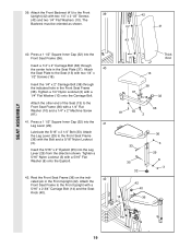
Insert the other Pad Tube (28) into the ends of the Left VKR Arm (79) and the Right VKR Arm (80). Attach the VKR Backrest (77) to the Right VKR Arm (80) with two 1/4Ó x 2Ó Machine Screws (81) and two 1/4Ó Flat Washers (10). Locate and open the parts bag labeled ÒVKR ASSEMBLY.Ó Press 1 1/2Ó Square Inner Caps (32) into the Leg Lever (29). Press two 3/4Ó Round Inner Caps (34) into the Seat Frame (36). Attach a VKR Armrest (78) to the VKR Upright (74) with two 5/16Ó x 3Ó Bolts (75) and two 5/16Ó Nylon Locknuts (3). 44 80 75 74 ...
Insert the other Pad Tube (28) into the ends of the Left VKR Arm (79) and the Right VKR Arm (80). Attach the VKR Backrest (77) to the Right VKR Arm (80) with two 1/4Ó x 2Ó Machine Screws (81) and two 1/4Ó Flat Washers (10). Locate and open the parts bag labeled ÒVKR ASSEMBLY.Ó Press 1 1/2Ó Square Inner Caps (32) into the Leg Lever (29). Press two 3/4Ó Round Inner Caps (34) into the Seat Frame (36). Attach a VKR Armrest (78) to the VKR Upright (74) with two 5/16Ó x 3Ó Bolts (75) and two 5/16Ó Nylon Locknuts (3). 44 80 75 74 ...