
English Manual
Page 2
...: Before beginning this manual. Cover the floor or carpet beneath the home gym for foot protection when exercising. 4. If the cables bind while you feel pain or dizziness at all instructions before using the home gym. 3. Table of Contents Important Precautions 2 Before You... Begin 3 Assembly 4 Cable Diagrams 23 Adjustment 25 Trouble-shooting and Maintenance 26 Weight Resistance Chart 27 Ordering Replacement Parts Back Cover Full 90-day Warranty Back...
...: Before beginning this manual. Cover the floor or carpet beneath the home gym for foot protection when exercising. 4. If the cables bind while you feel pain or dizziness at all instructions before using the home gym. 3. Table of Contents Important Precautions 2 Before You... Begin 3 Assembly 4 Cable Diagrams 23 Adjustment 25 Trouble-shooting and Maintenance 26 Weight Resistance Chart 27 Ordering Replacement Parts Back Cover Full 90-day Warranty Back...

English Manual
Page 4
..., it to do otherwise. Place the chart on the floor or work table and use it is not in the shipping box. Cable Assembly This assembly completes the cables and pulleys that support your new equipment is designed to complete the process over a couple of the Assembly Process Frame Assembly You will...
..., it to do otherwise. Place the chart on the floor or work table and use it is not in the shipping box. Cable Assembly This assembly completes the cables and pulleys that support your new equipment is designed to complete the process over a couple of the Assembly Process Frame Assembly You will...
English Manual
Page 9
... holes (94), and a 3/8" Nylon Locknut (50). Do not tighten the Nylon Locknuts yet. 14. Attach the Weight Top Frame (66) to the Weight Base (5) with a Cable Trap (25) onto a 3/8" x 4" Bolt (78). Slide a Top Weight (16) onto the Weight Guides (15). Slide a 3 1/2" Pulley (24) with a 3/8" x 2 3/4" Bolt (46), two 3/8" Flat Washers (48), and...
... holes (94), and a 3/8" Nylon Locknut (50). Do not tighten the Nylon Locknuts yet. 14. Attach the Weight Top Frame (66) to the Weight Base (5) with a Cable Trap (25) onto a 3/8" x 4" Bolt (78). Slide a Top Weight (16) onto the Weight Guides (15). Slide a 3 1/2" Pulley (24) with a 3/8" x 2 3/4" Bolt (46), two 3/8" Flat Washers (48), and...

English Manual
Page 11
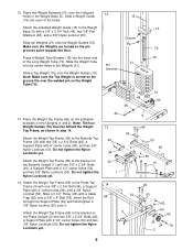
Slide a Butterfly Foam Pad (29) onto the lower end of the Pro Pulley. Make sure the Large Cable Trap is approximately 52" long and it onto the axle. Note: Place the Retainer ... end of the Right Butterfly Arm (11). Make sure the teeth on pages 23 and 24. For Cable identification and routing during steps 19 to 49, refer to the bracket on the back of the inverted ... to the bracket on the Left Butterfly Arm (10) with soapy water. Attach the Butterfly Cable to the Cable Diagrams and Cable ID Chart on the Retainer Rings bend towards the Cap as shown and slide it has a...
Slide a Butterfly Foam Pad (29) onto the lower end of the Pro Pulley. Make sure the Large Cable Trap is approximately 52" long and it onto the axle. Note: Place the Retainer ... end of the Right Butterfly Arm (11). Make sure the teeth on pages 23 and 24. For Cable identification and routing during steps 19 to 49, refer to the bracket on the back of the inverted ... to the bracket on the Left Butterfly Arm (10) with soapy water. Attach the Butterfly Cable to the Cable Diagrams and Cable ID Chart on the Retainer Rings bend towards the Cap as shown and slide it has a...

English Manual
Page 12
...Jamnuts must be mount- ed underneath the welded bracket. 11 1 84 Bracket 63 73 24. It is oriented as shown. 57 22. Make sure the Cable is oriented exactly as shown. 22 53 27 73 32 73 24 50 22 Bracket 50 23. Attach the Pulley to the bracket on the...). 21. Remove both 3 1/2" Pulleys (24) from the pre-assem- 21 bled Small Pulley Bracket (22). Attach the Butterfly Cable (73) to the Small Pulley Bracket (22) with the ball. 59 48 Wrap the Ab Cable (74) around a 3 1/2" Pulley (24) in the Butterfly Upright (1) with a 3/8" x 1" Bolt (84) and two 3/8" Nylon Jamnuts (63). ...
...Jamnuts must be mount- ed underneath the welded bracket. 11 1 84 Bracket 63 73 24. It is oriented as shown. 57 22. Make sure the Cable is oriented exactly as shown. 22 53 27 73 32 73 24 50 22 Bracket 50 23. Attach the Pulley to the bracket on the...). 21. Remove both 3 1/2" Pulleys (24) from the pre-assem- 21 bled Small Pulley Bracket (22). Attach the Butterfly Cable (73) to the Small Pulley Bracket (22) with the ball. 59 48 Wrap the Ab Cable (74) around a 3 1/2" Pulley (24) in the Butterfly Upright (1) with a 3/8" x 1" Bolt (84) and two 3/8" Nylon Jamnuts (63). ...

English Manual
Page 13
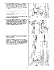
...x 2" Bolt (54) and a 3/8" Nylon Locknut (50). Remove both 3 1/2" Pulleys (24) from the pre-assembled Adjustable Pulley Plates (23). Attach the Pulley and a Cable Trap (25) to the Small Pulley Bracket (22) with a 3/8" x 1 3/4" Bolt (57) and a 3/8" Nylon Locknut (50). Make sure the Pulley Bracket is oriented ... Pulley Plates (23) with a 3/8" x 2" Bolt (54) and a 3/8" Nylon Locknut (50). Wrap the Ab Cable (74) around a 3 1/2" Pulley (24) in the direction shown. 25. Make sure the Cable Trap and the Pulley Plates are oriented as shown. 27. Attach the Pulley to the top hole in 27...
...x 2" Bolt (54) and a 3/8" Nylon Locknut (50). Remove both 3 1/2" Pulleys (24) from the pre-assembled Adjustable Pulley Plates (23). Attach the Pulley and a Cable Trap (25) to the Small Pulley Bracket (22) with a 3/8" x 1 3/4" Bolt (57) and a 3/8" Nylon Locknut (50). Make sure the Pulley Bracket is oriented ... Pulley Plates (23) with a 3/8" x 2" Bolt (54) and a 3/8" Nylon Locknut (50). Wrap the Ab Cable (74) around a 3 1/2" Pulley (24) in the direction shown. 25. Make sure the Cable Trap and the Pulley Plates are oriented as shown. 27. Attach the Pulley to the top hole in 27...
English Manual
Page 14
...1/2" Pulley (24) in 29 the direction shown. Attach the "U"-Bracket (97) to a "U"Bracket (97) with a 3/8" Nylon Jamnut (63). Slide the Pulley and a Cable Trap (25) onto the 3/8" x 3 1/2" Carriage Bolt (95) already inserted into the Butterfly Base (4). Attach the Pulley inside the indicated bracket on the Weight Base (5).... Nylon Locknut; Secure the Pulley with a 1/4" Flat Washer (71) and a 1/4" 30 Nylon Locknut (68). Attach the threaded end of the Ab Cable (74) to the hole in the Short Weight Tube (17) with a 3/8" x 1 3/4" Bolt (57) and a 3/8" Nylon Locknut (50). Route the threaded ...
...1/2" Pulley (24) in 29 the direction shown. Attach the "U"-Bracket (97) to a "U"Bracket (97) with a 3/8" Nylon Jamnut (63). Slide the Pulley and a Cable Trap (25) onto the 3/8" x 3 1/2" Carriage Bolt (95) already inserted into the Butterfly Base (4). Attach the Pulley inside the indicated bracket on the Weight Base (5).... Nylon Locknut; Secure the Pulley with a 1/4" Flat Washer (71) and a 1/4" 30 Nylon Locknut (68). Attach the threaded end of the Ab Cable (74) to the hole in the Short Weight Tube (17) with a 3/8" x 1 3/4" Bolt (57) and a 3/8" Nylon Locknut (50). Route the threaded ...

English Manual
Page 15
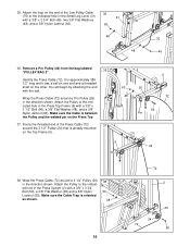
... 3/8" Nylon Jamnut (63) from the bag labeled "PULLEY BAG 2". Route the Low Pulley Cable (75) under a Pro Pulley (26) as shown. 23 50 25 24 75 34. 31. Identify the Low Pulley Cable (75). Make sure the Cable Trap is oriented as shown. 60 1 24 25 63 75 33. Make sure the...and it has a ball on one end and a loop on the Butterfly Base (4). Remove a Pro Pulley (26) from the 34 3/8" x 4 3/4" Bolt (60) inserted into the Butterfly Upright (1) in the cable guide on the other. Attach the Pulley and a Cable Trap (25) to the 3/8" x 4 3/4" Bolt (60) with the loop through the ...
... 3/8" Nylon Jamnut (63) from the bag labeled "PULLEY BAG 2". Route the Low Pulley Cable (75) under a Pro Pulley (26) as shown. 23 50 25 24 75 34. 31. Identify the Low Pulley Cable (75). Make sure the Cable Trap is oriented as shown. 60 1 24 25 63 75 33. Make sure the...and it has a ball on one end and a loop on the Butterfly Base (4). Remove a Pro Pulley (26) from the 34 3/8" x 4 3/4" Bolt (60) inserted into the Butterfly Upright (1) in the cable guide on the other. Attach the Pulley and a Cable Trap (25) to the 3/8" x 4 3/4" Bolt (60) with the loop through the ...
English Manual
Page 16
... shown. It is already mounted on the Top Frame (9). 9 9 26 72 56 Pin 24 38. Attach the loop on the end of the Press Cable (72) 37 around a Pro Pulley (26) in the direction shown. Attach the Pulley to the indicated hole in the Press Top Frame (9) with a 3/8" x 3 3/4" Bolt (59), a 3/8" Flat Washer... is between the Pulley and the welded pin on the other. 35. Remove a Pro Pulley (26) from the bag labeled "PULLEY BAG 2". 36 Identify the Press Cable (72). Make sure the Cable is oriented as shown. 38 50 48 16 72 2 25 24 72 59 Route the threaded end of the Low Pulley...
... shown. It is already mounted on the Top Frame (9). 9 9 26 72 56 Pin 24 38. Attach the loop on the end of the Press Cable (72) 37 around a Pro Pulley (26) in the direction shown. Attach the Pulley to the indicated hole in the Press Top Frame (9) with a 3/8" x 3 3/4" Bolt (59), a 3/8" Flat Washer... is between the Pulley and the welded pin on the other. 35. Remove a Pro Pulley (26) from the bag labeled "PULLEY BAG 2". 36 Identify the Press Cable (72). Make sure the Cable is oriented as shown. 38 50 48 16 72 2 25 24 72 59 Route the threaded end of the Low Pulley...

English Manual
Page 17
... Pulley is mounted on the inside of the Press Upright (2) with a 3/8" x 3 1/4" Bolt (62), a 3/8" Flat Washer (48) and a 3/8" Nylon Locknut (50). Wrap the Press Cable (72) around a 3 1/2" Pulley (24) in the Press Frame (8) with a 3/8" x 3 1/4" Bolt (62), a 3/8" Flat Washer (48) and a 3/8" Nylon Locknut (50). Note...24 48 62 8 25 50 2 48 Small tube, last hole 27 62 32 72 62 48 72 8 24 50 42. 39. Then, route the Press Cable back through the opening in the Press Frame (8) with a 3/8" x 3 1/4" Bolt (62), a 3/8" Flat Washer (48), and a 3/8" Nylon Locknut (...
... Pulley is mounted on the inside of the Press Upright (2) with a 3/8" x 3 1/4" Bolt (62), a 3/8" Flat Washer (48) and a 3/8" Nylon Locknut (50). Wrap the Press Cable (72) around a 3 1/2" Pulley (24) in the Press Frame (8) with a 3/8" x 3 1/4" Bolt (62), a 3/8" Flat Washer (48) and a 3/8" Nylon Locknut (50). Note...24 48 62 8 25 50 2 48 Small tube, last hole 27 62 32 72 62 48 72 8 24 50 42. 39. Then, route the Press Cable back through the opening in the Press Frame (8) with a 3/8" x 3 1/4" Bolt (62), a 3/8" Flat Washer (48), and a 3/8" Nylon Locknut (...

English Manual
Page 18
...Pulley to near side of the Leg Press Lever (83) with a 3/8" x 4 1/4" Bolt (85), a 3/8" Flat Washer (48), and a 3/8" Nylon Locknut (50). Wrap the Press Cable (72) around a "V"-Pulley (27) 44 in the hole closest to the indicated hole on the far side 72 of the Leg Press Lever (83). Attach... earlier. Use the 3/8" x 4 3/4" Bolt (60) that was inserted in step 42 and secure the Pulley with the 3/8" Nylon 2 Jamnut (63). Make sure the Cable Trap is ori- 27 ented as shown. 18 50 24 25 102 25 72 60 24 63 Use the 3/8" x 4 3/4" Bolt (60) that was inserted in...
...Pulley to near side of the Leg Press Lever (83) with a 3/8" x 4 1/4" Bolt (85), a 3/8" Flat Washer (48), and a 3/8" Nylon Locknut (50). Wrap the Press Cable (72) around a "V"-Pulley (27) 44 in the hole closest to the indicated hole on the far side 72 of the Leg Press Lever (83). Attach... earlier. Use the 3/8" x 4 3/4" Bolt (60) that was inserted in step 42 and secure the Pulley with the 3/8" Nylon 2 Jamnut (63). Make sure the Cable Trap is ori- 27 ented as shown. 18 50 24 25 102 25 72 60 24 63 Use the 3/8" x 4 3/4" Bolt (60) that was inserted in...

English Manual
Page 19
...66) with a 5/16" x 1 3/4" Bolt (96) and a 5/16" Nylon Locknut (64). Attach the "U"-Bracket (97) to the hole in the direction shown. Wrap the Press Cable (72) over a 4 1/2" Pulley (82) 48 in the Long Weight Tube (70) with a 3/8" x 1 3/4" Bolt (57) and a 3/8" Nylon Locknut (50). Attach the threaded ...end of the Cable, as shown. 50 82 72 57 66 49. Attach the Pulley inside the indicated bracket on the Weight Base (5) in an earlier step. 72 24 5 ...
...66) with a 5/16" x 1 3/4" Bolt (96) and a 5/16" Nylon Locknut (64). Attach the "U"-Bracket (97) to the hole in the direction shown. Wrap the Press Cable (72) over a 4 1/2" Pulley (82) 48 in the Long Weight Tube (70) with a 3/8" x 1 3/4" Bolt (57) and a 3/8" Nylon Locknut (50). Attach the threaded ...end of the Cable, as shown. 50 82 72 57 66 49. Attach the Pulley inside the indicated bracket on the Weight Base (5) in an earlier step. 72 24 5 ...
English Manual
Page 22
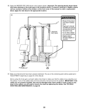
...slack in the appropriate location. 56 WEIDER PRO 9940 57. Before using the home gym, pull each cable a few times to make sure that all parts have been attached to the home gym in ADJUSTMENT, beginning on page 25 of this manual. IMPORTANT: If the cables are not properly installed, they ... properly tightened. The use of the cables does not move smoothly over the pulleys. If a decal is used. If one of the remaining parts will need to order a replacement decal. Apply the WEIDER PRO 9940 decal in the location shown. Make sure that the cables move smoothly, find and correct the ...
...slack in the appropriate location. 56 WEIDER PRO 9940 57. Before using the home gym, pull each cable a few times to make sure that all parts have been attached to the home gym in ADJUSTMENT, beginning on page 25 of this manual. IMPORTANT: If the cables are not properly installed, they ... properly tightened. The use of the cables does not move smoothly over the pulleys. If a decal is used. If one of the remaining parts will need to order a replacement decal. Apply the WEIDER PRO 9940 decal in the location shown. Make sure that the cables move smoothly, find and correct the ...

English Manual
Page 23
Cable Diagrams The Cable Diagrams below and on the next page show the correct route for each Cable. Make sure that the Cables are routed correctly, that the Pulleys move smoothly, and that the Cable Traps do not touch or bind the Cables. Low Pulley Cable (75) Ab Cable (74) 7 3 3 1 2 2 1 4 5 8 5 4 Butterfly Cable (73) 6 4 1 5 2 Cable ID Chart 73, 52" 75, 143.5" 3 74, 224" 72, 389.5" 23 Incorrect cable routing can damage the home gym. The numbers show the proper routing of the Butterfly Cable (73), the Ab Cable (74), the Low Pulley Cable (75) and the Press Cable (72).
Cable Diagrams The Cable Diagrams below and on the next page show the correct route for each Cable. Make sure that the Cables are routed correctly, that the Pulleys move smoothly, and that the Cable Traps do not touch or bind the Cables. Low Pulley Cable (75) Ab Cable (74) 7 3 3 1 2 2 1 4 5 8 5 4 Butterfly Cable (73) 6 4 1 5 2 Cable ID Chart 73, 52" 75, 143.5" 3 74, 224" 72, 389.5" 23 Incorrect cable routing can damage the home gym. The numbers show the proper routing of the Butterfly Cable (73), the Ab Cable (74), the Low Pulley Cable (75) and the Press Cable (72).

English Manual
Page 25
...Ab Strap to the High Pulley Station Attach the Lat Bar (61) to the Low Pulley Cable (75) with a Cable Clip (69). Line up for the exercise to be performed. 58 67 61 69 72 69...slide the Adjustment Tube (90) backwards or forwards in the correct starting position for the exercise to the cables and pulleys, the amount of resistance at each weight station. IMPORTANT: When using an attachment, make sure...exercise to see how the home gym should be attached between the Lat Bar and the High Cable so the Lat Bar is performed, the effectiveness of the exercise will go. Note: Due to...
...Ab Strap to the High Pulley Station Attach the Lat Bar (61) to the Low Pulley Cable (75) with a Cable Clip (69). Line up for the exercise to be performed. 58 67 61 69 72 69...slide the Adjustment Tube (90) backwards or forwards in the correct starting position for the exercise to the cables and pulleys, the amount of resistance at each weight station. IMPORTANT: When using an attachment, make sure...exercise to see how the home gym should be attached between the Lat Bar and the High Cable so the Lat Bar is performed, the effectiveness of the exercise will go. Note: Due to...

English Manual
Page 26
...moving one or both pulleys (24) to a different set of the "V"-Pulleys (27) on the Press Upright (2). Tightening the Cables If a cable slips off the pulleys often, the cable may have several different ways: The Adjustable Pulley Plates (23) have become twisted. If additional adjustment is first used on the back...103) at the desired height. 105 104 28 103 20 Trouble-shooting and Maintenance Inspect and tighten all parts each time you will tighten the cables. ther away from the Front Leg (20) and insert the Curl Post (104) into the Front Leg. Replace any one Pulley to be ...
...moving one or both pulleys (24) to a different set of the "V"-Pulleys (27) on the Press Upright (2). Tightening the Cables If a cable slips off the pulleys often, the cable may have several different ways: The Adjustable Pulley Plates (23) have become twisted. If additional adjustment is first used on the back...103) at the desired height. 105 104 28 103 20 Trouble-shooting and Maintenance Inspect and tighten all parts each time you will tighten the cables. ther away from the Front Leg (20) and insert the Curl Post (104) into the Front Leg. Replace any one Pulley to be ...

English Manual
Page 27
... are attached to the weight stacks can be tightened by using the Adjustable Pulley Plates (23) as friction between the cables, pulleys, and weight guides. The Press Cable (72) is the only cable attached to the 6 lb. top weight; Weight Plates Top 1 2 3 4 5 6 7 8 9 10 High Pulley (lbs.) 14 28 42 56 69 83 .... weight plates. "Top" refers to the large weight stack. the other numbers refer to the 12.5 lb. The Press Cable (72) can also be tightened by tightening the Ab Cable (74) as described above or by moving the "V"-Pulleys as described on the previous page. 74 64 97 72 96 71...
... are attached to the weight stacks can be tightened by using the Adjustable Pulley Plates (23) as friction between the cables, pulleys, and weight guides. The Press Cable (72) is the only cable attached to the 6 lb. top weight; Weight Plates Top 1 2 3 4 5 6 7 8 9 10 High Pulley (lbs.) 14 28 42 56 69 83 .... weight plates. "Top" refers to the large weight stack. the other numbers refer to the 12.5 lb. The Press Cable (72) can also be tightened by tightening the Ab Cable (74) as described above or by moving the "V"-Pulleys as described on the previous page. 74 64 97 72 96 71...

English Manual
Page 30
... 1 Small Pulley Bracket 76 2 1" Round Inner Cap 23 2 Adjustable Pulley Plate 77 2 Press Arm 24 20 3 1/2" Pulley 78 1 3/8" x 4" Bolt 25 16 Cable Trap 79 5 1/4" x 2 1/2" Bolt 26 2 Pro Pulley 80 1 1" Tap Screw 27 4 "V"-Pulley 81 1 Ab Strap 28 13 2" Square Inner Cap 82 2 4 1/2" Pulley 29 2 Butterfly Foam Pad 83 1 Leg Press Lever 30...
... 1 Small Pulley Bracket 76 2 1" Round Inner Cap 23 2 Adjustable Pulley Plate 77 2 Press Arm 24 20 3 1/2" Pulley 78 1 3/8" x 4" Bolt 25 16 Cable Trap 79 5 1/4" x 2 1/2" Bolt 26 2 Pro Pulley 80 1 1" Tap Screw 27 4 "V"-Pulley 81 1 Ab Strap 28 13 2" Square Inner Cap 82 2 4 1/2" Pulley 29 2 Butterfly Foam Pad 83 1 Leg Press Lever 30...


