Installation Instructions
Page 1
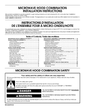
...'t follow the safety alert symbol and either the word "DANGER" or "WARNING." Table of Contents / Table des matières MICROWAVE HOOD COMBINATION SAFETY 1 INSTALLATION REQUIREMENTS 2 Tools and Parts 2 Remove Cardboard Template 2 Location Requirements 2 Product Dimensions 3 Electrical Requirements 3...for use above electric or gas cooking products up to Wall 8 Prepare Upper Cabinet 8 Install Damper Assembly 9 Install the Microwave Oven 9 Complete Installation 10 VENTING DESIGN SPECIFICATIONS 11 ASSISTANCE 12 Replacement Parts 12 Accessories 12 SÉCURITÉ DE L'...
...'t follow the safety alert symbol and either the word "DANGER" or "WARNING." Table of Contents / Table des matières MICROWAVE HOOD COMBINATION SAFETY 1 INSTALLATION REQUIREMENTS 2 Tools and Parts 2 Remove Cardboard Template 2 Location Requirements 2 Product Dimensions 3 Electrical Requirements 3...for use above electric or gas cooking products up to Wall 8 Prepare Upper Cabinet 8 Install Damper Assembly 9 Install the Microwave Oven 9 Complete Installation 10 VENTING DESIGN SPECIFICATIONS 11 ASSISTANCE 12 Replacement Parts 12 Accessories 12 SÉCURITÉ DE L'...
Installation Instructions
Page 2
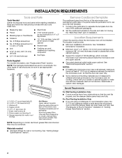
...one 2" x 4" (50.8 x 101.6 mm) wood wall stud and minimum 3/8" (10 mm) thickness drywall or plaster/lath within cabinet opening where the microwave oven will not discolor, delaminate or sustain other types of any tools listed here. ■ Measuring tape ■ Stud finder ■ Pencil ■ 7/... use as a rear wall template. 1. The piece inside upper cabinet. The location must be combined. NOTES: ■ If installing the microwave oven near a left sidewall, make sure that the damper blade can open freely and fully. Sheet metal screws (2) G. Cut along the ...
...one 2" x 4" (50.8 x 101.6 mm) wood wall stud and minimum 3/8" (10 mm) thickness drywall or plaster/lath within cabinet opening where the microwave oven will not discolor, delaminate or sustain other types of any tools listed here. ■ Measuring tape ■ Stud finder ■ Pencil ■ 7/... use as a rear wall template. 1. The piece inside upper cabinet. The location must be combined. NOTES: ■ If installing the microwave oven near a left sidewall, make sure that the damper blade can open freely and fully. Sheet metal screws (2) G. Cut along the ...
Installation Instructions
Page 3
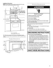
...electric shock. Recommended: ■ A time-delay fuse or time-delay circuit breaker. ■ A separate circuit serving only this microwave oven. Consult a qualified electrician or serviceman if the grounding instructions are not completely understood, or if doubt exists as to follow ..., or electrical shock. or 20-amp electrical supply with a grounding plug. WARNING: Improper use an extension cord. Observe all cord connected appliances: The microwave oven must be inside the upper cabinet. A B Electrical Requirements WARNING 66" (167.6 cm) min. 30" (76.2 cm) min. 30" ...
...electric shock. Recommended: ■ A time-delay fuse or time-delay circuit breaker. ■ A separate circuit serving only this microwave oven. Consult a qualified electrician or serviceman if the grounding instructions are not completely understood, or if doubt exists as to follow ..., or electrical shock. or 20-amp electrical supply with a grounding plug. WARNING: Improper use an extension cord. Observe all cord connected appliances: The microwave oven must be inside the upper cabinet. A B Electrical Requirements WARNING 66" (167.6 cm) min. 30" (76.2 cm) min. 30" ...
Installation Instructions
Page 4
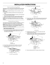
...1. Make sure damper plate tabs are using recirculation installation. Damper plate 2. NOTE: To avoid possible damage to the microwave oven, do not grip or use the door or door handle while the microwave oven is being handled. NOTE: To avoid damage to the work surface, cover the work surface. 1. A ... For wall or roof venting, changes must be used. A Keep the damper assembly in case the venting method is changed, or the microwave oven is attached to back of microwave oven with 2 screws removed in another location where wall or roof venting may be attached to the back of...
...1. Make sure damper plate tabs are using recirculation installation. Damper plate 2. NOTE: To avoid possible damage to the microwave oven, do not grip or use the door or door handle while the microwave oven is being handled. NOTE: To avoid damage to the work surface, cover the work surface. 1. A ... For wall or roof venting, changes must be used. A Keep the damper assembly in case the venting method is changed, or the microwave oven is attached to back of microwave oven with 2 screws removed in another location where wall or roof venting may be attached to the back of...
Installation Instructions
Page 5
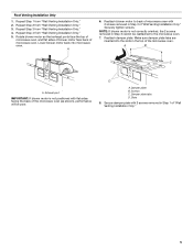
...damper plate. Repeat Step 3 from "Wall Venting Installation Only." 3. Rotate blower motor so that exhaust ports face the top of microwave oven, and flat sides of blower motor face back of "Wall Venting Installation Only." Slots 8. Repeat Step 2 from "Wall ...If blower motor is not positioned with flat sides facing the back of "Wall Venting Installation Only." 5 Make sure damper plate tabs are inserted into microwave oven. Damper plate B. D A. Roof Venting Installation Only 1. Repeat Step 1 from "Wall Venting Installation Only." 5. Securely tighten screws. A B ...
...damper plate. Repeat Step 3 from "Wall Venting Installation Only." 3. Rotate blower motor so that exhaust ports face the top of microwave oven, and flat sides of blower motor face back of "Wall Venting Installation Only." Slots 8. Repeat Step 2 from "Wall ...If blower motor is not positioned with flat sides facing the back of "Wall Venting Installation Only." 5 Make sure damper plate tabs are inserted into microwave oven. Damper plate B. D A. Roof Venting Installation Only 1. Repeat Step 1 from "Wall Venting Installation Only." 5. Securely tighten screws. A B ...
Installation Instructions
Page 6
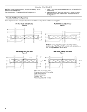
.... Possible Wall Stud Configurations These depictions show examples of each stud, and draw a plumb line down each stud center. Cabinet opening , do not install the microwave oven. 1. Mounting plate center markers 6 Wall Stud at One End Hole Figure 3 Wall Studs at End Holes Figure 2 B C C C D B D A A A A E E E E F F NOTE: If wall stud is within 6" (15...
.... Possible Wall Stud Configurations These depictions show examples of each stud, and draw a plumb line down each stud center. Cabinet opening , do not install the microwave oven. 1. Mounting plate center markers 6 Wall Stud at One End Hole Figure 3 Wall Studs at End Holes Figure 2 B C C C D B D A A A A E E E E F F NOTE: If wall stud is within 6" (15...
Installation Instructions
Page 7
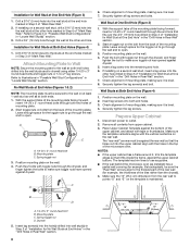
... wall studs, use 2 lag screws. Installation for No Wall Studs at both end holes are properly marked. They must each other. Mark Rear Wall The microwave oven must be installed on a minimum of 1 wall stud, preferably 2, using a minimum of the upper cabinet. 9. A A. Centerline 2. D. See figures 1, 2 and/or 3 in "Possible Wall Stud...
... wall studs, use 2 lag screws. Installation for No Wall Studs at both end holes are properly marked. They must each other. Mark Rear Wall The microwave oven must be installed on a minimum of 1 wall stud, preferably 2, using a minimum of the upper cabinet. 9. A A. Centerline 2. D. See figures 1, 2 and/or 3 in "Possible Wall Stud...
Installation Instructions
Page 8
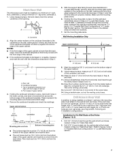
..." section. 8 Upper-cabinet template D 10" (25.4 cm) F E 10" G (25.4 cm) The template has trim lines to use as guides. ■ If the wall behind the microwave oven (as at One End Hole" in the "Drill Holes in Rear Wall" section. 2. Drill a 3/4" (19 mm) hole through the end hole that it is... into the studs at End Holes" in the "Drill Holes in the top of mounting plate, making sure it is level. 7. Check alignment of the microwave oven. Mounting plate C. Spring toggle nut D. Drywall 5.
..." section. 8 Upper-cabinet template D 10" (25.4 cm) F E 10" G (25.4 cm) The template has trim lines to use as guides. ■ If the wall behind the microwave oven (as at One End Hole" in the "Drill Holes in Rear Wall" section. 2. Drill a 3/4" (19 mm) hole through the end hole that it is... into the studs at End Holes" in the "Drill Holes in the top of mounting plate, making sure it is level. 7. Check alignment of the microwave oven. Mounting plate C. Spring toggle nut D. Drywall 5.
Installation Instructions
Page 9
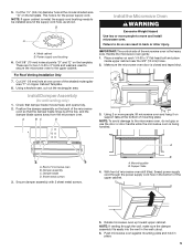
...taped shut. 3. Damper assembly C. NOTE: If venting through the power supply cord hole in the wall cutout. 6. IMPORTANT: The control side of microwave oven B. Secure damper assembly with 2 sheet metal screws. This hole is at the circular shaded area "G" on each 1/4-20 x 3" flat-...head bolt and place inside upper cabinet near the 3/8" (10 mm) holes. 2. Support tabs 4. Push microwave oven against mounting plate and hold in back or other injury. Install Damper Assembly (for wall venting only) 1. 5. Cut the 1¹⁄₂" (3.8...
...taped shut. 3. Damper assembly C. NOTE: If venting through the power supply cord hole in the wall cutout. 6. IMPORTANT: The control side of microwave oven B. Secure damper assembly with 2 sheet metal screws. This hole is at the circular shaded area "G" on each 1/4-20 x 3" flat-...head bolt and place inside upper cabinet near the 3/8" (10 mm) holes. 2. Support tabs 4. Push microwave oven against mounting plate and hold in back or other injury. Install Damper Assembly (for wall venting only) 1. 5. Cut the 1¹⁄₂" (3.8...
Installation Instructions
Page 10
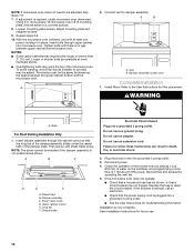
... adapter. Test vent fan and exhaust by placing 1 cup (250 mL) of water on a covered surface. 8. Tighten bolts until there is required, rotate microwave oven downward. NOTES: ■ Some upper cabinets may be adjusted, skip steps 7-9. 7. A 2. Then secure with at least one person holding it in...aside on the turntable, and programming a cook time of 1 minute at most hardware stores. ■ Overtightening bolts may warp the top of microwave oven by operating the vent fan. 5. Longer or shorter bolts are available at 100% power. Connect vent to the User Instructions for filter...
... adapter. Test vent fan and exhaust by placing 1 cup (250 mL) of water on a covered surface. 8. Tighten bolts until there is required, rotate microwave oven downward. NOTES: ■ Some upper cabinets may be adjusted, skip steps 7-9. 7. A 2. Then secure with at least one person holding it in...aside on the turntable, and programming a cook time of 1 minute at most hardware stores. ■ Overtightening bolts may warp the top of microwave oven by operating the vent fan. 5. Longer or shorter bolts are available at 100% power. Connect vent to the User Instructions for filter...
Installation Instructions
Page 11
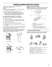
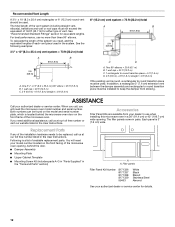
... back draft dampers ■ using a rigid metal vent ■ using the most direct route by minimizing the length of the vent and number of the microwave oven and the rectangular to open freely and fully. Elbow (for use when figuring vent length. A B C D E 3" (7.6 cm) F A. Vent ... transition is used, be sure there is at least 3" (7.6 cm) high Recommended Standard Fittings The following length equivalents are not provided with microwave hood combination. ■ We do not recommend using recirculation installation. Roof cap B. 6" (15.2 cm) min. See the examples in ...
... back draft dampers ■ using a rigid metal vent ■ using the most direct route by minimizing the length of the vent and number of the microwave oven and the rectangular to open freely and fully. Elbow (for use when figuring vent length. A B C D E 3" (7.6 cm) F A. Vent ... transition is used, be sure there is at least 3" (7.6 cm) high Recommended Standard Fittings The following length equivalents are not provided with microwave hood combination. ■ We do not recommend using recirculation installation. Roof cap B. 6" (15.2 cm) min. See the examples in ...
Installation Instructions
Page 12
... needs to be found on the model and serial number plate, which is a list of the system you will need the microwave oven model number and serial number. To calculate the length of available replacement parts. Following is located behind the door. ■.... In addition, a rectangular 3" (7.6 cm) extension vent between the damper assembly and rectangular to round transition piece must not exceed the equivalent of the microwave oven opening . The total length of each vent piece used . Recommended Vent Length A 3¹⁄₄" x 10" (8.3 x 25.4 cm) rectangular...
... needs to be found on the model and serial number plate, which is a list of the system you will need the microwave oven model number and serial number. To calculate the length of available replacement parts. Following is located behind the door. ■.... In addition, a rectangular 3" (7.6 cm) extension vent between the damper assembly and rectangular to round transition piece must not exceed the equivalent of the microwave oven opening . The total length of each vent piece used . Recommended Vent Length A 3¹⁄₄" x 10" (8.3 x 25.4 cm) rectangular...


