

Service Manual
Page 4
.... ADC: Automatic Density Control NCS: Non-Contact Sensor BTR: Bias Transfer Roller PHD: Imaging Unit CRUM: Customer Replaceable Unit Monitor PL: FRU Parts List. A note can provide additional information related to a specific subject or add a comment on a specific topic or to , or destruction ... PTL: Pre-Transfer Lamp DRV: Motor Driver Board RMI: Routine Maintenance Item ESD: Electrostatic Discharge RMS: Root-Mean-Square LSU: Laser Scanning Unit RTC: Charge Roller MCU: Engine Control Board Note A note indicates an operating or maintenance procedure, practice or condition that...
.... ADC: Automatic Density Control NCS: Non-Contact Sensor BTR: Bias Transfer Roller PHD: Imaging Unit CRUM: Customer Replaceable Unit Monitor PL: FRU Parts List. A note can provide additional information related to a specific subject or add a comment on a specific topic or to , or destruction ... PTL: Pre-Transfer Lamp DRV: Motor Driver Board RMI: Routine Maintenance Item ESD: Electrostatic Discharge RMS: Root-Mean-Square LSU: Laser Scanning Unit RTC: Charge Roller MCU: Engine Control Board Note A note indicates an operating or maintenance procedure, practice or condition that...

Service Manual
Page 6
... clean the product. Position the power cord so that it is easily accessible during an emergency. Service Manual v For 220 VAC printers, do not apply more than 140 volts RMS between the supply conductors or between either supply conductor and ground. If necessary, contact...a licensed electrician to any liquid or foreign material is a qualified service technician. Plug the three-wire power cord (with conductive parts may power down the printer during servicing so that the reader is spilled into a grounded AC outlet only. Disconnect the power cord in the following cases...
... clean the product. Position the power cord so that it is easily accessible during an emergency. Service Manual v For 220 VAC printers, do not apply more than 140 volts RMS between the supply conductors or between either supply conductor and ground. If necessary, contact...a licensed electrician to any liquid or foreign material is a qualified service technician. Plug the three-wire power cord (with conductive parts may power down the printer during servicing so that the reader is spilled into a grounded AC outlet only. Disconnect the power cord in the following cases...

Service Manual
Page 7
...component or electrical subassembly from its anti-static bag, place it . ■ Before removing the protective material from the leads of parts when mounting or inserting them , are ready to install it on Printed Circuit Boards (PCB's). Electrostatic Discharge (ESD) Precautions Some ...replacement devices. Be sure to remove the wrist strap before applying power to the unit to damage by static electricity. vi Phaser 3450 Laser Printer These components include Integrated Circuits (ICs), Large-Scale Integrated circuits (LSIs), field-effect transistors and other safety precautions. ■...
...component or electrical subassembly from its anti-static bag, place it . ■ Before removing the protective material from the leads of parts when mounting or inserting them , are ready to install it on Printed Circuit Boards (PCB's). Electrostatic Discharge (ESD) Precautions Some ...replacement devices. Be sure to remove the wrist strap before applying power to the unit to damage by static electricity. vi Phaser 3450 Laser Printer These components include Integrated Circuits (ICs), Large-Scale Integrated circuits (LSIs), field-effect transistors and other safety precautions. ■...

Service Manual
Page 10
... this product complies with the requirements of an unintentional radiator in part 15 of the FCC rules. These standards are designed to mitigate interference caused or received by Xerox can affect the emission and immunity compliance and could void the user's authority to operate ...use shielded interface cables. Service Manual ix To ensure compliance, use in a residential environment based on the printer away from the receiver ■ Consult the dealer, Xerox service, or an experienced radio/television technician for radio noise emissions from another device. In the United ...
... this product complies with the requirements of an unintentional radiator in part 15 of the FCC rules. These standards are designed to mitigate interference caused or received by Xerox can affect the emission and immunity compliance and could void the user's authority to operate ...use shielded interface cables. Service Manual ix To ensure compliance, use in a residential environment based on the printer away from the receiver ■ Consult the dealer, Xerox service, or an experienced radio/television technician for radio noise emissions from another device. In the United ...

Service Manual
Page 11
"Part 3: Limits - "Information technology equipment - Section 2: Limits for equipment with the following standards and other normative documents: In the European Union Following the provisions ...15 - 80 MHz, 3 V, 80% AM @ 1 kHz x Phaser 3450 Laser Printer Declaration of Conformity Xerox Corporation, declares, under our sole responsibility that the printer to which this declaration relates, is in low-voltage supply systems for harmonic current emissions (equipment input current less than or equal to 16A." "Part 3: Limits - Class B. Section 3: Limitation of measurement. " CISPR...
"Part 3: Limits - "Information technology equipment - Section 2: Limits for equipment with the following standards and other normative documents: In the European Union Following the provisions ...15 - 80 MHz, 3 V, 80% AM @ 1 kHz x Phaser 3450 Laser Printer Declaration of Conformity Xerox Corporation, declares, under our sole responsibility that the printer to which this declaration relates, is in low-voltage supply systems for harmonic current emissions (equipment input current less than or equal to 16A." "Part 3: Limits - Class B. Section 3: Limitation of measurement. " CISPR...

Service Manual
Page 14
... Discharge (ESD) Precautions vi Service Safety Summary vii Regulatory Specifications ix 1 General Information Printer Introduction and Overview 1-2 Printer Configurations 1-3 Parts of the Printer 1-4 Exterior 1-4 Phaser 3450 Front Panel Configuration 1-5 Phaser 3450 Laser Printer Rear View 1-6 Main Board 1-7 Service Parts 1-8 Consumables 1-9 Supply Life Counter Behavior 1-10 Printer Specifications 1-11 Physical Dimensions and Clearances 1-11 Functional Specifications 1-12 Electrical Specifications 1-12 Environmental...
... Discharge (ESD) Precautions vi Service Safety Summary vii Regulatory Specifications ix 1 General Information Printer Introduction and Overview 1-2 Printer Configurations 1-3 Parts of the Printer 1-4 Exterior 1-4 Phaser 3450 Front Panel Configuration 1-5 Phaser 3450 Laser Printer Rear View 1-6 Main Board 1-7 Service Parts 1-8 Consumables 1-9 Supply Life Counter Behavior 1-10 Printer Specifications 1-11 Physical Dimensions and Clearances 1-11 Functional Specifications 1-12 Electrical Specifications 1-12 Environmental...

Service Manual
Page 16
... Jam 2 4-13 CRUM Toner Error 4-14 5 Print-Quality Troubleshooting Print-Quality Problems Overview 5-2 Defects Associated with Specific Printer Components 5-2 Front Panel Test Print 5-3 Deletions 5-4 Fusing 5-5 Resolution 5-5 Registration and Skew 5-6 Skips or Smears 5-6 ... 7-2 Recommended Tools 7-2 Cleaning 7-2 Printing a Cleaning Sheet 7-3 8 Service Parts Disassembly Overview 8-2 Standard Orientation of the Printer 8-2 General Notes on Disassembly 8-3 Preparation 8-3 Removing Service Parts and Consumables 8-4 Print Cartridge Removal (PL 9.1.8 8-4 Transfer Roller Removal (...
... Jam 2 4-13 CRUM Toner Error 4-14 5 Print-Quality Troubleshooting Print-Quality Problems Overview 5-2 Defects Associated with Specific Printer Components 5-2 Front Panel Test Print 5-3 Deletions 5-4 Fusing 5-5 Resolution 5-5 Registration and Skew 5-6 Skips or Smears 5-6 ... 7-2 Recommended Tools 7-2 Cleaning 7-2 Printing a Cleaning Sheet 7-3 8 Service Parts Disassembly Overview 8-2 Standard Orientation of the Printer 8-2 General Notes on Disassembly 8-3 Preparation 8-3 Removing Service Parts and Consumables 8-4 Print Cartridge Removal (PL 9.1.8 8-4 Transfer Roller Removal (...

Service Manual
Page 17
... 9.1.20 8-22 Main Fan Assembly (PL 9.1.19 8-23 Sub Fan Assembly (PL 9.3.35 8-24 Exit Roller Assembly (PL 9.3.21) Transport Roller Assembly (PL9.3.24 8-25 Laser Assembly (PL 9.1.16 8-27 Print Cartridge Interconnect Assembly (PL 9.3.53 8-29 Registration Transport Assembly (PL 9.1.9 8-30 Registration Sensor (PL 9.7.10 8-31 Tray 1 Feed Roller... (PL 9.3.67 8-36 Tray 2 Pick Roller (PL 9.3.67.3 8-41 Power Supply Board (PL 9.1.13 8-42 Duplex Assembly (PL 8.8.2 8-45 Exit Sensor (PL 9.3.62 8-45 9 Parts Lists Serial Number Format 9-2 Using the Parts List 9-3 xvi Phaser 3450 Laser Printer
... 9.1.20 8-22 Main Fan Assembly (PL 9.1.19 8-23 Sub Fan Assembly (PL 9.3.35 8-24 Exit Roller Assembly (PL 9.3.21) Transport Roller Assembly (PL9.3.24 8-25 Laser Assembly (PL 9.1.16 8-27 Print Cartridge Interconnect Assembly (PL 9.3.53 8-29 Registration Transport Assembly (PL 9.1.9 8-30 Registration Sensor (PL 9.7.10 8-31 Tray 1 Feed Roller... (PL 9.3.67 8-36 Tray 2 Pick Roller (PL 9.3.67.3 8-41 Power Supply Board (PL 9.1.13 8-42 Duplex Assembly (PL 8.8.2 8-45 Exit Sensor (PL 9.3.62 8-45 9 Parts Lists Serial Number Format 9-2 Using the Parts List 9-3 xvi Phaser 3450 Laser Printer

Service Manual
Page 20
General Information In this chapter... ■ Printer Introduction and Overview ■ Printer Configurations ■ Parts of the Printer ■ Phaser 3450 Front Panel Configuration ■ Main Board ■ Service Parts ■ Consumables ■ Printer Specifications 1 Chapter
General Information In this chapter... ■ Printer Introduction and Overview ■ Printer Configurations ■ Parts of the Printer ■ Phaser 3450 Front Panel Configuration ■ Main Board ■ Service Parts ■ Consumables ■ Printer Specifications 1 Chapter

Service Manual
Page 23
Paper Level Indicator 5. Front Panel 8. Tray 3 (Optional 500 Sheet Feeder) 4. Output Support 7. Parts of the Printer Exterior 9 10 8 7 6 1 2 3 5 4 s3450-160 1. Right (Main Board) Cover 6. Top Output Tray (Facedown) 9. Tray 1 (MPT) 2. Tray 2 (500 Sheet Feeder) 3. Top Cover 10. Print Cartridge 1-4 Phaser 3450 Laser Printer Service Manual
Paper Level Indicator 5. Front Panel 8. Tray 3 (Optional 500 Sheet Feeder) 4. Output Support 7. Parts of the Printer Exterior 9 10 8 7 6 1 2 3 5 4 s3450-160 1. Right (Main Board) Cover 6. Top Output Tray (Facedown) 9. Tray 1 (MPT) 2. Tray 2 (500 Sheet Feeder) 3. Top Cover 10. Print Cartridge 1-4 Phaser 3450 Laser Printer Service Manual

Service Manual
Page 27
Fuser Assembly s3450-163 Phaser 3450 Laser Printer Service Manual Transfer Roller 1-8 3. Feed Roller 2. Service Parts 2 1 3 1.
Fuser Assembly s3450-163 Phaser 3450 Laser Printer Service Manual Transfer Roller 1-8 3. Feed Roller 2. Service Parts 2 1 3 1.

Service Manual
Page 29
... near end-of-life and end-of -use messages. Consumables Print Cartridge* Service Parts Fuser Assembly Transfer Roller Feed Roller Kit Print Life High Capacity 10,000 Standard Capacity 5,000 125,000 125,000 125,000 1-10 Phaser 3450 Laser Printer Service Manual The trigger values are as follows: ■ 10K Cartridge: 78,000...
... near end-of-life and end-of -use messages. Consumables Print Cartridge* Service Parts Fuser Assembly Transfer Roller Feed Roller Kit Print Life High Capacity 10,000 Standard Capacity 5,000 125,000 125,000 125,000 1-10 Phaser 3450 Laser Printer Service Manual The trigger values are as follows: ■ 10K Cartridge: 78,000...

Service Manual
Page 40
... is available for an optional 8 Mbyte flash memory DIMM for fonts, forms, and macros. Major Assemblies and Functions The Phaser 3450 Laser Printer contains several subsystems. Each subsystem contains Service Parts identified in the parts list in Chapter 8 of this manual. The board provides one expansion slot that allows available memory to the Removal and... bit RISC processor and comes with a standard memory capacity of Operation 2-7 Theory of 32 Mbytes. For information on repairing or replacing sub-assemblies and Service Parts, refer to be replaceable except as...
... is available for an optional 8 Mbyte flash memory DIMM for fonts, forms, and macros. Major Assemblies and Functions The Phaser 3450 Laser Printer contains several subsystems. Each subsystem contains Service Parts identified in the parts list in Chapter 8 of this manual. The board provides one expansion slot that allows available memory to the Removal and... bit RISC processor and comes with a standard memory capacity of Operation 2-7 Theory of 32 Mbytes. For information on repairing or replacing sub-assemblies and Service Parts, refer to be replaceable except as...

Service Manual
Page 42
.... Theory of the principle operating voltages and control signals for the following printer operations: ■ Main Drive Motor ■ Fuser Assembly ■ High Voltage Power Supply (HVPS) ■ Laser Scanner Unit (LSU) ■ Sensors ■ Solenoids ■ Thermistor ■ All parts related to the xerographic process ■ Optional Paper Tray 3 and Tray 1 The...
.... Theory of the principle operating voltages and control signals for the following printer operations: ■ Main Drive Motor ■ Fuser Assembly ■ High Voltage Power Supply (HVPS) ■ Laser Scanner Unit (LSU) ■ Sensors ■ Solenoids ■ Thermistor ■ All parts related to the xerographic process ■ Optional Paper Tray 3 and Tray 1 The...

Service Manual
Page 44
... 2-11 The Pick-Up Roller assembly includes a mechanical clutch, released by the Paper Out Sensor. Paper Out Sensor The paper supply is a field replaceable Service Part. The transfer roller provides a high positive potential on the opposite side of the print media so the heat roller can embed the melted toner in...
... 2-11 The Pick-Up Roller assembly includes a mechanical clutch, released by the Paper Out Sensor. Paper Out Sensor The paper supply is a field replaceable Service Part. The transfer roller provides a high positive potential on the opposite side of the print media so the heat roller can embed the melted toner in...

Service Manual
Page 49
... 2, or 3 02 Jam At Top 03 Jam At Exit 04 Jam At Duplex 05 Jam At Tray/Remove Tray 2 3-2 Phaser 3450 Laser Printer Service Manual The error codes that service personnel and users record errors exactly when reporting problems with an error message or jam can be... or to verify a specific printer part is not visible on the front panel, the Fault History and Jam History list errors reported by displaying the Fault History or Jam History on page 3-9. Introduction This section covers troubleshooting procedures for the Phaser 3450 Laser Printer front panel error messages and codes...
... 2, or 3 02 Jam At Top 03 Jam At Exit 04 Jam At Duplex 05 Jam At Tray/Remove Tray 2 3-2 Phaser 3450 Laser Printer Service Manual The error codes that service personnel and users record errors exactly when reporting problems with an error message or jam can be... or to verify a specific printer part is not visible on the front panel, the Fault History and Jam History list errors reported by displaying the Fault History or Jam History on page 3-9. Introduction This section covers troubleshooting procedures for the Phaser 3450 Laser Printer front panel error messages and codes...
Service Manual
Page 51
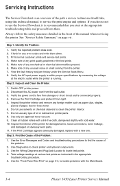
...paper, dust or loose toner. 6. Check for damaged wires, loose connections, toner leakage, and damaged or obviously worn parts. 11. Switch OFF printer power. 2. If the Print Cartridge appears obviously damaged, replace with cold water. 10. Servicing Instructions The Service Flowchart is...reported problem does exist. 2. Use the Wiring Diagrams and Plug/Jack Locator to isolate problems with the Main Board. 3-4 Phaser 3450 Laser Printer Service Manual Always follow the safety measures detailed in the appropriate troubleshooting procedure. 5. Verify the AC input power supply is ...
...paper, dust or loose toner. 6. Check for damaged wires, loose connections, toner leakage, and damaged or obviously worn parts. 11. Switch OFF printer power. 2. If the Print Cartridge appears obviously damaged, replace with cold water. 10. Servicing Instructions The Service Flowchart is...reported problem does exist. 2. Use the Wiring Diagrams and Plug/Jack Locator to isolate problems with the Main Board. 3-4 Phaser 3450 Laser Printer Service Manual Always follow the safety measures detailed in the appropriate troubleshooting procedure. 5. Verify the AC input power supply is ...
Service Manual
Page 52
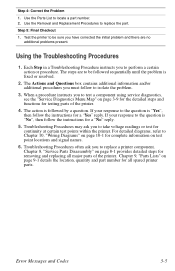
... Procedures may ask you must follow the instructions for continuity at certain test points within the printer. Use the Removal and Replacement Procedures to locate a part number. 2. The Actions and Questions box contains additional information and/or additional procedures you to... using service diagnostics, see the "Service Diagnostics Menu Map" on page 8-1 provides detailed steps for testing parts of the printer. Use the Parts List to replace the part. Step 5: Final Checkout 1. Using the Troubleshooting Procedures 1. When a procedure instructs you to perform a certain...
... Procedures may ask you must follow the instructions for continuity at certain test points within the printer. Use the Removal and Replacement Procedures to locate a part number. 2. The Actions and Questions box contains additional information and/or additional procedures you to... using service diagnostics, see the "Service Diagnostics Menu Map" on page 8-1 provides detailed steps for testing parts of the printer. Use the Parts List to replace the part. Step 5: Final Checkout 1. Using the Troubleshooting Procedures 1. When a procedure instructs you to perform a certain...

Service Manual
Page 53
... actuation. The main purpose of a parent assembly, you should replace the entire parent assembly. 3-6 Phaser 3450 Laser Printer Service Manual When you are instructed to take a voltage reading, the black probe (-) is generally connected to a pin that is part of voltage readings is to take voltage, continuity or resistance readings on pin 5 of all...
... actuation. The main purpose of a parent assembly, you should replace the entire parent assembly. 3-6 Phaser 3450 Laser Printer Service Manual When you are instructed to take a voltage reading, the black probe (-) is generally connected to a pin that is part of voltage readings is to take voltage, continuity or resistance readings on pin 5 of all...

Service Manual
Page 61
Troubleshooting Reference Applicable Parts Fuser heat lamp Fuser overheat thermostat Thermistor Main Board Wiring and Plug/Jack Map References "Print Engine Interconnect Diagram" on page 10-2 Troubleshooting Procedure Steps Actions and Questions 1 Remove Fuser 2 Check resistance of heat lamp. No - Go to Step 2. Replace Main Board. 3-14 Phaser 3450 Laser Printer Service Manual Yes Go...
Troubleshooting Reference Applicable Parts Fuser heat lamp Fuser overheat thermostat Thermistor Main Board Wiring and Plug/Jack Map References "Print Engine Interconnect Diagram" on page 10-2 Troubleshooting Procedure Steps Actions and Questions 1 Remove Fuser 2 Check resistance of heat lamp. No - Go to Step 2. Replace Main Board. 3-14 Phaser 3450 Laser Printer Service Manual Yes Go...