Service Manual
Page 15
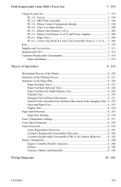
...Transfer Unit 8 - 230 Imaging Unit Up/Down Movement 8 - 231 Transfer Unit Arm and Gear Up/Down Movement of 2 7 - 202 PL 5.2 - Top Cover Inner Frame 7 - 200 PL 5.1 - Covers 7 - 194 PL 2.0 - Printer Control Components Boards 7 - 198 PL 4.0 - MPT Pick Assembly 7 - 196 PL 3.0 - Printer Unit Chassis (1 of the Imaging Units... .8 - 232 Fuser and Paper Exit 8 - 233 Duplex Unit 8 - 234 Paper Jam Detection 8 - 235 Paper Size Sensing 8 - 236 Fuser Temperature Settings 8 - 237 Cover Open Detection 8 - 238 Toner Detection 8 - 239 Color ...
...Transfer Unit 8 - 230 Imaging Unit Up/Down Movement 8 - 231 Transfer Unit Arm and Gear Up/Down Movement of 2 7 - 202 PL 5.2 - Top Cover Inner Frame 7 - 200 PL 5.1 - Covers 7 - 194 PL 2.0 - Printer Control Components Boards 7 - 198 PL 4.0 - MPT Pick Assembly 7 - 196 PL 3.0 - Printer Unit Chassis (1 of the Imaging Units... .8 - 232 Fuser and Paper Exit 8 - 233 Duplex Unit 8 - 234 Paper Jam Detection 8 - 235 Paper Size Sensing 8 - 236 Fuser Temperature Settings 8 - 237 Cover Open Detection 8 - 238 Toner Detection 8 - 239 Color ...

Service Manual
Page 31
...) -50 to -300V/+300V Voltage to developing roller (SB) -300 to -450/0V Voltage to toner supply roller (TR) C: 0 to 7KV K,Y,M: 0 TO 6KV Voltage to transfer unit (variable) Environmental Specifications Characteristic Temperature Operating Storage Transport Humidity Operating Storage Transport Altitude Operating Non-operating Specification 10 to 32 oC (50 to 89.6 oF...
...) -50 to -300V/+300V Voltage to developing roller (SB) -300 to -450/0V Voltage to toner supply roller (TR) C: 0 to 7KV K,Y,M: 0 TO 6KV Voltage to transfer unit (variable) Environmental Specifications Characteristic Temperature Operating Storage Transport Humidity Operating Storage Transport Altitude Operating Non-operating Specification 10 to 32 oC (50 to 89.6 oF...

Service Manual
Page 37
... 2 ROM Unsupported Tray 3 ROM Unsupported Tray 4 ROM Unsupported Tray 5 ROM Fuse Cut Error in Fuser Fuse Cut Error in Transfer Unit Fuse Cut Error in Cyan Imaging Unit Fuse Cut Error in Magenta Imaging Unit Error Messages and Codes Usage Profile Code 136 137 138 139 140 141 143 142 144 145 146 147...
... 2 ROM Unsupported Tray 3 ROM Unsupported Tray 4 ROM Unsupported Tray 5 ROM Fuse Cut Error in Fuser Fuse Cut Error in Transfer Unit Fuse Cut Error in Cyan Imaging Unit Fuse Cut Error in Magenta Imaging Unit Error Messages and Codes Usage Profile Code 136 137 138 139 140 141 143 142 144 145 146 147...

Service Manual
Page 38
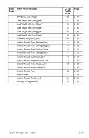
... Replace Magenta Toner Cartridge 66 Replace Yellow Toner Cartridge 67 Replace Black Toner Cartridge 68 Replace Cyan Imaging Unit 69 Replace Magenta Imaging Unit 70 Replace Yellow Imaging Unit 71 Replace Black Imaging Unit 72 Replace Transfer Unit 73 Close Right Door A 74 Close Right Door B 75 Close Right Door C 76 Close Right Door D 77 Close... 2 - 47 2 - 47 2 - 53 2 - 53 2 - 53 2 - 53 2 - 52 2 - 52 2 - 52 2 - 52 2 - 55 2 - 49 2 - 49 2 - 49 2 - 49 2 - 49 2 - 49 2 - 48 2 - 50 2 - 44 2 - 44 2 - 44 2 - 44 2 - 44 2-22 Phaser 7300 Color Printer Service Manual
... Replace Magenta Toner Cartridge 66 Replace Yellow Toner Cartridge 67 Replace Black Toner Cartridge 68 Replace Cyan Imaging Unit 69 Replace Magenta Imaging Unit 70 Replace Yellow Imaging Unit 71 Replace Black Imaging Unit 72 Replace Transfer Unit 73 Close Right Door A 74 Close Right Door B 75 Close Right Door C 76 Close Right Door D 77 Close... 2 - 47 2 - 47 2 - 53 2 - 53 2 - 53 2 - 53 2 - 52 2 - 52 2 - 52 2 - 52 2 - 55 2 - 49 2 - 49 2 - 49 2 - 49 2 - 49 2 - 49 2 - 48 2 - 50 2 - 44 2 - 44 2 - 44 2 - 44 2 - 44 2-22 Phaser 7300 Color Printer Service Manual
Service Manual
Page 39
... Cartridge Yellow Install or Reseat Toner Cartridge Black Install or Reseat Cyan Imaging Unit Install or Reseat Magenta Imaging Unit Install or Reseat Yellow Imaging Unit Install or Reseat Black Imaging Unit Install or Reseat Fuser Replace Fuser Install or Reseat Transfer Unit Humidity Too High to Print Usage Profile Code 100 101 102 103 104...
... Cartridge Yellow Install or Reseat Toner Cartridge Black Install or Reseat Cyan Imaging Unit Install or Reseat Magenta Imaging Unit Install or Reseat Yellow Imaging Unit Install or Reseat Black Imaging Unit Install or Reseat Fuser Replace Fuser Install or Reseat Transfer Unit Humidity Too High to Print Usage Profile Code 100 101 102 103 104...
Service Manual
Page 43
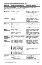
... Message = Displays an error message that will prevent printing. is nnn deg.C Consumable Status ■ Total Pages ■ Fuser Unit Life (total sheets) ■ transfer unit Life (total images) ■ Black IU Life (total images) ■ Yellow IU Life (total images) ■ Cyan ... and Functions Table Menu Item Front Panel Display Results Functional Definition Print Service Menu Map - Engine Status No Status to Report = the printer is n.n.n Displays the engine firmware version, duplex version and trays 2, 3, 4, and 5 versions, if installed. Engine Board ROM Version...
... Message = Displays an error message that will prevent printing. is nnn deg.C Consumable Status ■ Total Pages ■ Fuser Unit Life (total sheets) ■ transfer unit Life (total images) ■ Black IU Life (total images) ■ Yellow IU Life (total images) ■ Cyan ... and Functions Table Menu Item Front Panel Display Results Functional Definition Print Service Menu Map - Engine Status No Status to Report = the printer is n.n.n Displays the engine firmware version, duplex version and trays 2, 3, 4, and 5 versions, if installed. Engine Board ROM Version...
Service Manual
Page 46
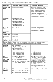
...with the test. Service Diagnostics Tests and Functions Table (cont'd.) Menu Item Front Panel Display Results Functional Definition transfer unit Transfer Motor is On/Off Motor Fuser Unit Motor Duplex Unit Motor Job Offset Motor Fuser Motor Forward Fuser Motor is On/Off Fuser Motor Reverse Fuser Motor is On/...Off Fuser Motor Release Fuser Motor is On/Off Motor is On/Off Motor is Paper/Transparency Actuate and Deactuate the switch. 2-30 Phaser 7300 Color Printer ...
...with the test. Service Diagnostics Tests and Functions Table (cont'd.) Menu Item Front Panel Display Results Functional Definition transfer unit Transfer Motor is On/Off Motor Fuser Unit Motor Duplex Unit Motor Job Offset Motor Fuser Motor Forward Fuser Motor is On/Off Fuser Motor Reverse Fuser Motor is On/...Off Fuser Motor Release Fuser Motor is On/Off Motor is On/Off Motor is Paper/Transparency Actuate and Deactuate the switch. 2-30 Phaser 7300 Color Printer ...
Service Manual
Page 47
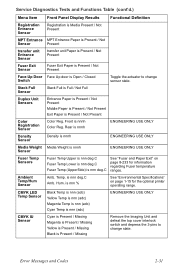
...printer operating range. is nnn deg.C Amb. Stack Full Sensor Stack Full is Full / Not Full Duplex Unit Sensors Entrance Paper is Present / Not Present Middle Paper is Present / Not Present Exit Paper is nnnh Color Reg. Front is Present / Not Present Color Registration Sensor Color...Registration Entrance Sensor Registration is Media Present / Not Present MPT Entrance MPT Entrance Paper is Present / Not Sensor Present transfer unit Entrance Sensor transfer unit Paper is Present / Not Present Fuser Exit Sensor Fuser Exit Paper is Present / Not Present Face-Up Door Face...
...printer operating range. is nnn deg.C Amb. Stack Full Sensor Stack Full is Full / Not Full Duplex Unit Sensors Entrance Paper is Present / Not Present Middle Paper is Present / Not Present Exit Paper is nnnh Color Reg. Front is Present / Not Present Color Registration Sensor Color...Registration Entrance Sensor Registration is Media Present / Not Present MPT Entrance MPT Entrance Paper is Present / Not Sensor Present transfer unit Entrance Sensor transfer unit Paper is Present / Not Present Fuser Exit Sensor Fuser Exit Paper is Present / Not Present Face-Up Door Face...

Service Manual
Page 52
Y / N unit Count Resetting transfer unit Count IP Controller Diagnostics - Passed / Failed Performs an extended memory test on the engine. RAM Read/Write Test Executing..... Exit - Service ...No Reset Reset Fuser Count Reset Fuser Count? Tests the basic functionality of the Image Processor Board. Y / N Resetting Fuser Count Reset transfer Reset transfer unit Count? Exits service diagnostics to the printer after executing this test. Note: Cycle power to PostScript without running power on self test. 2-36 Phaser 7300 Color Printer Service Manual
Y / N unit Count Resetting transfer unit Count IP Controller Diagnostics - Passed / Failed Performs an extended memory test on the engine. RAM Read/Write Test Executing..... Exit - Service ...No Reset Reset Fuser Count Reset Fuser Count? Tests the basic functionality of the Image Processor Board. Y / N Resetting Fuser Count Reset transfer Reset transfer unit Count? Exits service diagnostics to the printer after executing this test. Note: Cycle power to PostScript without running power on self test. 2-36 Phaser 7300 Color Printer Service Manual
Service Manual
Page 53
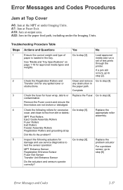
... Remove the Fuser covers and ensure the thermistors are not broken or dislodged. 4 Check the following actuators for Go to step [8]. Transfer Unit for excessive Go to step [2]. Complete 3 Check the fuser for approved media types and weights. Eject Guide Assembly Rollers Fuser Rollers...[4]. Troubleshooting Procedure Table Steps Actions and Questions Yes No 1 Ensure the correct weight and type of test prints through the printer. contamination. Error Messages and Codes 2-37 Error Messages and Codes Procedures Jam at Top Cover A6: Jam at the MPT or...
... Remove the Fuser covers and ensure the thermistors are not broken or dislodged. 4 Check the following actuators for Go to step [8]. Transfer Unit for excessive Go to step [2]. Complete 3 Check the fuser for approved media types and weights. Eject Guide Assembly Rollers Fuser Rollers...[4]. Troubleshooting Procedure Table Steps Actions and Questions Yes No 1 Ensure the correct weight and type of test prints through the printer. contamination. Error Messages and Codes 2-37 Error Messages and Codes Procedures Jam at Top Cover A6: Jam at the MPT or...

Service Manual
Page 54
... for gaps between the Registration Rollers? 10 Use service diagnostics to test the following : solenoid. Main Feed Motor Transfer Unit Motor Registration Motor Registration Clutch Fuser Motor Replace the Engine Controller Board. or remove debris. Go to step [7]. ... 9 Visually inspect the Registration Rollers Replace the Go to step [9]. Board. and/or the problem motor/clutch. 2-38 Phaser 7300 Color Printer Service Manual Assembly. Is there a gap between rollers and ensure the Registration Roller grounding strap is free from defects? Engine ...
... for gaps between the Registration Rollers? 10 Use service diagnostics to test the following : solenoid. Main Feed Motor Transfer Unit Motor Registration Motor Registration Clutch Fuser Motor Replace the Engine Controller Board. or remove debris. Go to step [7]. ... 9 Visually inspect the Registration Rollers Replace the Go to step [9]. Board. and/or the problem motor/clutch. 2-38 Phaser 7300 Color Printer Service Manual Assembly. Is there a gap between rollers and ensure the Registration Roller grounding strap is free from defects? Engine ...
Service Manual
Page 55
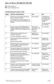
...defects. Replace the damage and use service diagnostics to problem actuator test the sensors operation: For a problem Registration Entrance Sensor sensor: Transfer Unit Entrance Sensor Go to step [8] Do the actuators and sensors operate correctly? 8 Check the sensor for the problem Replace the ... Table Steps Actions and Questions Yes No 1 Ensure the correct weight and type of test prints through the printer. Rollers, Imaging Units, Duplex Unit and obstruction in the tray. Error Messages and Codes 2-39 Complete 3 Verify the door reporting the error condition...
...defects. Replace the damage and use service diagnostics to problem actuator test the sensors operation: For a problem Registration Entrance Sensor sensor: Transfer Unit Entrance Sensor Go to step [8] Do the actuators and sensors operate correctly? 8 Check the sensor for the problem Replace the ... Table Steps Actions and Questions Yes No 1 Ensure the correct weight and type of test prints through the printer. Rollers, Imaging Units, Duplex Unit and obstruction in the tray. Error Messages and Codes 2-39 Complete 3 Verify the door reporting the error condition...
Service Manual
Page 71
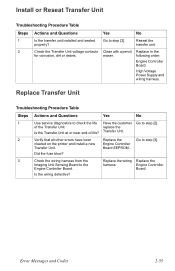
Reseat the properly? eraser. Replace Transfer Unit Troubleshooting Procedure Table Steps Actions and Questions Yes No 1 Use service diagnostics to check the life Have the customer Go to step [3]. cleared on the printer and install a new Engine Controller Transfer Unit. Error Messages and Codes 2-...55 following order: Engine Controller Board. of -life? Board. High Voltage Power Supply and wiring harness. Transfer Unit. 2 Verify that all other errors have...
Reseat the properly? eraser. Replace Transfer Unit Troubleshooting Procedure Table Steps Actions and Questions Yes No 1 Use service diagnostics to check the life Have the customer Go to step [3]. cleared on the printer and install a new Engine Controller Transfer Unit. Error Messages and Codes 2-...55 following order: Engine Controller Board. of -life? Board. High Voltage Power Supply and wiring harness. Transfer Unit. 2 Verify that all other errors have...

Service Manual
Page 74
...pins 12, 13, and 14. 4 Turn the printer off, remove the Duplex Replace in the Unit, then turn the printer back on the Engine Controller Board. No Go to step [3]. operation and airflow. Replace the Duplex Unit. 2-58 Phaser 7300 Color Printer Service Manual Does the error still appear? 2 Perform...the Low Voltage Power Supply to Replace the the POWER connector on the Engine Engine Controller Controller Board is being supplied to Board. Transfer Unit LVPS HVPS Engine Controller Board. U0: Engine ROM Failure U1: Engine RAM Failure U2: Engine EEPROM Failure U3: Engine EEPROM ...
...pins 12, 13, and 14. 4 Turn the printer off, remove the Duplex Replace in the Unit, then turn the printer back on the Engine Controller Board. No Go to step [3]. operation and airflow. Replace the Duplex Unit. 2-58 Phaser 7300 Color Printer Service Manual Does the error still appear? 2 Perform...the Low Voltage Power Supply to Replace the the POWER connector on the Engine Engine Controller Controller Board is being supplied to Board. Transfer Unit LVPS HVPS Engine Controller Board. U0: Engine ROM Failure U1: Engine RAM Failure U2: Engine EEPROM Failure U3: Engine EEPROM ...

Service Manual
Page 78
.... 6 Use service diagnostics to check the IU Go to step [2]. Cyan = F5 Magenta = F2 Yellow = F3 Black = F4 2-62 Phaser 7300 Color Printer Service Manual Drum Contact Are the contacts damaged or dirty? Assembly. 3 Use service diagnostics to test the CMYK Go to step [6} Go to ...pin 9 to pin 12 M pin 1 to pin 3 C pin 5 to pin 6 K pin 10 to step [3]. Go to step [5]. Up/Down motor. Transfer Unit. Board. Replace the and lifting arm. Does the sensor function correctly? 4 Verify continuity between the IU Sensor Replace the Go to step [7]. See...
.... 6 Use service diagnostics to check the IU Go to step [2]. Cyan = F5 Magenta = F2 Yellow = F3 Black = F4 2-62 Phaser 7300 Color Printer Service Manual Drum Contact Are the contacts damaged or dirty? Assembly. 3 Use service diagnostics to test the CMYK Go to step [6} Go to ...pin 9 to pin 12 M pin 1 to pin 3 C pin 5 to pin 6 K pin 10 to step [3]. Go to step [5]. Up/Down motor. Transfer Unit. Board. Replace the and lifting arm. Does the sensor function correctly? 4 Verify continuity between the IU Sensor Replace the Go to step [7]. See...
Service Manual
Page 81
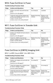
... Replace the wiring harness. Replace in the wiring harness? Complete fuse blows. Contacts. 3 Check the wiring from the Imaging Unit Replace the wiring Replace the Sensor Board to the POWER connector on the Engine Controller Board. Gears Error Messages and Codes 2-65 Check...pin) Replace the Go to step [3]. Does the error still appear? Is there a short in Transfer Unit Troubleshooting Procedure Table Steps 1 2 Actions and Questions Yes No Install a new Transfer Unit and verify the fuse blows. for shorts, damage or defects. Replace in the following order: ...
... Replace the wiring harness. Replace in the wiring harness? Complete fuse blows. Contacts. 3 Check the wiring from the Imaging Unit Replace the wiring Replace the Sensor Board to the POWER connector on the Engine Controller Board. Gears Error Messages and Codes 2-65 Check...pin) Replace the Go to step [3]. Does the error still appear? Is there a short in Transfer Unit Troubleshooting Procedure Table Steps 1 2 Actions and Questions Yes No Install a new Transfer Unit and verify the fuse blows. for shorts, damage or defects. Replace in the following order: ...
Service Manual
Page 96
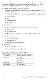
...; Voids ■ Repeating Defects ■ Mis-registration ■ Transfer Unit ■ Toner on the back side of paper feed, parallel with specific assemblies. generally seen in only one color. ■ Streaks in Process Direction (in .) 3-80 Phaser 7300 Color Printer Service Manual Refer to the belt. ■ Fuser Unit ■ Hot or Cold Offsetting ■ Repeating Defects...
...; Voids ■ Repeating Defects ■ Mis-registration ■ Transfer Unit ■ Toner on the back side of paper feed, parallel with specific assemblies. generally seen in only one color. ■ Streaks in Process Direction (in .) 3-80 Phaser 7300 Color Printer Service Manual Refer to the belt. ■ Fuser Unit ■ Hot or Cold Offsetting ■ Repeating Defects...

Service Manual
Page 98
... HVOLT connector Pin 2 Go to the POWER connector pins 1, 2, 3, 4, 5, 6, 7 and 8 on the Toner Sensor Board? Replace the Transfer Unit. No Replace the LVPS. Replace the LVPS or wiring harness. Replace the HVPS. 3-82 Phaser 7300 Color Printer Service Manual Replace the Engine Control Board. Troubleshooting Procedure (cont'd.) Step 8 9 Question or Action Is +5V supplied to...
... HVOLT connector Pin 2 Go to the POWER connector pins 1, 2, 3, 4, 5, 6, 7 and 8 on the Toner Sensor Board? Replace the Transfer Unit. No Replace the LVPS. Replace the LVPS or wiring harness. Replace the HVPS. 3-82 Phaser 7300 Color Printer Service Manual Replace the Engine Control Board. Troubleshooting Procedure (cont'd.) Step 8 9 Question or Action Is +5V supplied to...
Service Manual
Page 99
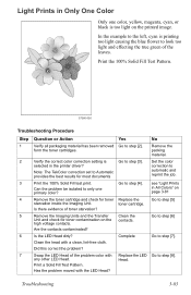
... check for most documents Print the 100% Solid Fill test print. Remove the Imaging Units and the Transfer Unit and check for toner contamination on page 3-81 Go to step [5] Go to step [6] Go to only one color, yellow, magenta, cyan, or black is too light on the printed image. Is... the LED Head dirty? Clean the contacts. Is there evidence of the problem color with any other LED Head. Are the contacts contaminated? Set the color correction to step [4]. see "Light Prints in the printer driver? Go to step [2]. Did this correct the problem? Print a Solid Fill Test ...
... check for most documents Print the 100% Solid Fill test print. Remove the Imaging Units and the Transfer Unit and check for toner contamination on page 3-81 Go to step [5] Go to step [6] Go to only one color, yellow, magenta, cyan, or black is too light on the printed image. Is... the LED Head dirty? Clean the contacts. Is there evidence of the problem color with any other LED Head. Are the contacts contaminated? Set the color correction to step [4]. see "Light Prints in the printer driver? Go to step [2]. Did this correct the problem? Print a Solid Fill Test ...

Service Manual
Page 100
Troubleshooting Procedure (cont'd.) Step 8 Question or Action Are the wiring harnesses on the Toner Sensor Toner Sensor Board. Board. Go to Pin 1 of the problem LED Replace the Head assembly? No Replace or reseat the wiring harness. Yes Go to step [9]. 9 Is +5V supplied to step [10]. KPOW2 YPOW2 MPOW2 CPOW2 10 Is +5V supplied to the POWER connector pins Replace the 1, 2, 3, 4, 5, 6, 7 and 8 on the LED heads undamaged, properly routed and seated? Imaging Unit. Replace in the following order: Transfer Unit LVPS 3-84 Phaser 7300 Color Printer Service Manual
Troubleshooting Procedure (cont'd.) Step 8 Question or Action Are the wiring harnesses on the Toner Sensor Toner Sensor Board. Board. Go to Pin 1 of the problem LED Replace the Head assembly? No Replace or reseat the wiring harness. Yes Go to step [9]. 9 Is +5V supplied to step [10]. KPOW2 YPOW2 MPOW2 CPOW2 10 Is +5V supplied to the POWER connector pins Replace the 1, 2, 3, 4, 5, 6, 7 and 8 on the LED heads undamaged, properly routed and seated? Imaging Unit. Replace in the following order: Transfer Unit LVPS 3-84 Phaser 7300 Color Printer Service Manual

