
User Manual
Page 3
... Features ...7 Package Contents 8 Front View and Controls 9 Installing Your LCD Monitor 10 2 Installation Connecting Your LCD Monitor to a Computer 11 Method 1: Analog (D-SUB) Connection 11 Method 2: Digital(DVI) Connection 12 Using Your LCD Monitor 13 3 OSD MENU Using the OSD Menu 14 The OSD Options 15 ...4 Technical Information Preset Mode Timing Chart 18 DVI Connector PIN Assignment 19 D-SUB Connector PIN Assignment 20 Plug and Play 21 Visual Inspection 21 Troubleshooting 22 2 Xerox© LCD Monitor User...
... Features ...7 Package Contents 8 Front View and Controls 9 Installing Your LCD Monitor 10 2 Installation Connecting Your LCD Monitor to a Computer 11 Method 1: Analog (D-SUB) Connection 11 Method 2: Digital(DVI) Connection 12 Using Your LCD Monitor 13 3 OSD MENU Using the OSD Menu 14 The OSD Options 15 ...4 Technical Information Preset Mode Timing Chart 18 DVI Connector PIN Assignment 19 D-SUB Connector PIN Assignment 20 Plug and Play 21 Visual Inspection 21 Troubleshooting 22 2 Xerox© LCD Monitor User...
User Manual
Page 4
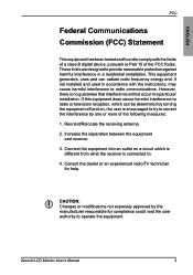
Consult the dealer or an experienced radio/TV technician for compliance could void the user authority to operate the equipment. Xerox© LCD Monitor User's Manual 3 This equipment generates, uses and can be determined by turning the equipment off and on a circuit which can radiate radio frequency energy and, ...
Consult the dealer or an experienced radio/TV technician for compliance could void the user authority to operate the equipment. Xerox© LCD Monitor User's Manual 3 This equipment generates, uses and can be determined by turning the equipment off and on a circuit which can radiate radio frequency energy and, ...

User Manual
Page 5
... the risk of the serial/model plate. • Never overload wall outlets and extensions. • Use and handle the power cord with a wet hand. 4 Xerox© LCD Monitor User's Manual The grounding pin on the AC power cord. • Do not pull the AC power cord. Do not handle the AC power...
... the risk of the serial/model plate. • Never overload wall outlets and extensions. • Use and handle the power cord with a wet hand. 4 Xerox© LCD Monitor User's Manual The grounding pin on the AC power cord. • Do not pull the AC power cord. Do not handle the AC power...

User Manual
Page 6
... damage. • Do not install the equipment near water. • Never expose the equipment to direct sunlight, as the equipment may cause poor ventilation. Xerox© LCD Monitor User's Manual (continued on the equipment. Leave an open space around the equipment. • Never place the equipment :on a bed, sofa, rug, or any...
... damage. • Do not install the equipment near water. • Never expose the equipment to direct sunlight, as the equipment may cause poor ventilation. Xerox© LCD Monitor User's Manual (continued on the equipment. Leave an open space around the equipment. • Never place the equipment :on a bed, sofa, rug, or any...

User Manual
Page 7
Liquid is spilled into the product. The power cord or plug is abnormal. 6 Xerox© LCD Monitor User's Manual a. b. An object falls onto or into the product . e. The product has been dropped or damaged. d. c. Important Safety Instructions • If any of the following conditions occur, unplug the power cord from the outlet and request service from qualified personnel. The product's display is damaged.
Liquid is spilled into the product. The power cord or plug is abnormal. 6 Xerox© LCD Monitor User's Manual a. b. An object falls onto or into the product . e. The product has been dropped or damaged. d. c. Important Safety Instructions • If any of the following conditions occur, unplug the power cord from the outlet and request service from qualified personnel. The product's display is damaged.
User Manual
Page 8
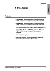
... well as VESA resolution standards. • Universal power supply. • Microsoft© Windows 9x/2000/XP compatible and VESA Display Data Channel(DDC)1/2B compatible. Xerox© LCD Monitor User's Manual 7
... well as VESA resolution standards. • Universal power supply. • Microsoft© Windows 9x/2000/XP compatible and VESA Display Data Channel(DDC)1/2B compatible. Xerox© LCD Monitor User's Manual 7
User Manual
Page 9
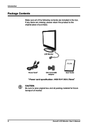
LCD Monitor Power Cord* DVI-I to D-SUB Adapter User Guide * Power cord specification : H05 VV-F 3G 0.75mm2 CAUTION: Be sure to save original box and all of the following contents are missing, please return this product to the original place of monitor. 8 Xerox© LCD Monitor User's Manual Introduction Package Contents Make sure all packing material for future transport of purchase. If any items are included in the box.
LCD Monitor Power Cord* DVI-I to D-SUB Adapter User Guide * Power cord specification : H05 VV-F 3G 0.75mm2 CAUTION: Be sure to save original box and all of the following contents are missing, please return this product to the original place of monitor. 8 Xerox© LCD Monitor User's Manual Introduction Package Contents Make sure all packing material for future transport of purchase. If any items are included in the box.

User Manual
Page 10
Xerox© LCD Monitor User's Manual 9 And press to activate the items you highlight . 2 DOWN/UP In OSD mode, press the DOWN/UP buttons to move the selection highlight ... View and Controls Introduction ENGLISH 1 2 3 45 1 MENU Press once to optimize performance based on the VGA signal. 4 LED The LED light indicates when the LCD monitor is activated (blue light indicates power on and blue flash indicates power saving). 5 POWER/ Turns the LCD...
Xerox© LCD Monitor User's Manual 9 And press to activate the items you highlight . 2 DOWN/UP In OSD mode, press the DOWN/UP buttons to move the selection highlight ... View and Controls Introduction ENGLISH 1 2 3 45 1 MENU Press once to optimize performance based on the VGA signal. 4 LED The LED light indicates when the LCD monitor is activated (blue light indicates power on and blue flash indicates power saving). 5 POWER/ Turns the LCD...
User Manual
Page 11
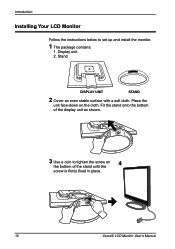
Place the unit face-down on the bottom of the stand until the 4 screw is firmly fixed in place. 10 Xerox© LCD Monitor User's Manual Introduction Installing Your LCD Monitor Follow the instructions below to tighten the screw on the cloth. Stand DISPLAY UNIT STAND 2 Cover an even stable surface with a soft cloth. Fit the stand onto the bottom of the display unit as shown. 3 Use a coin to set up and install the monitor. 1 The package contains: 1. Display unit 2.
Place the unit face-down on the bottom of the stand until the 4 screw is firmly fixed in place. 10 Xerox© LCD Monitor User's Manual Introduction Installing Your LCD Monitor Follow the instructions below to tighten the screw on the cloth. Stand DISPLAY UNIT STAND 2 Cover an even stable surface with a soft cloth. Fit the stand onto the bottom of the display unit as shown. 3 Use a coin to set up and install the monitor. 1 The package contains: 1. Display unit 2.
User Manual
Page 12
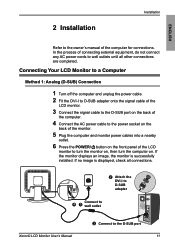
Connecting Your LCD Monitor to a Computer Method 1: Analog (D-SUB) Connection 1 Turn off the computer and unplug the power cable. 2 Fit the DVI-I to D-SUB adapter 4 5 Connect to wall outlet Xerox© LCD Monitor User's Manual 3 Connect to wall outlets until all connections. 2 Attach the DVI-I to D-...SUB adapter onto the signal cable of the LCD monitor. 3 Connect the signal cable to the D-SUB port on the back...
Connecting Your LCD Monitor to a Computer Method 1: Analog (D-SUB) Connection 1 Turn off the computer and unplug the power cable. 2 Fit the DVI-I to D-SUB adapter 4 5 Connect to wall outlet Xerox© LCD Monitor User's Manual 3 Connect to wall outlets until all connections. 2 Attach the DVI-I to D-...SUB adapter onto the signal cable of the LCD monitor. 3 Connect the signal cable to the D-SUB port on the back...

User Manual
Page 13
.... 3 Connect the AC power cable to the power socket on the back of the monitor. 4 Plug the computer and monitor power cables into a nearby outlet. 5 Press the POWER/ button on . The OSD... displays: 12 12 DIGITAL INPUT • Press the UP or DOWN button to turn the monitor on, then turn the computer on the front panel of range", please follow the instructions below to set... button to highight the (INPUT SELECT) icon, then press the MENU button. If the monitor displays an image, the monitor is displayed, check all connections. 3 4 Connect to wall outlet 2 Connect to the ...
.... 3 Connect the AC power cable to the power socket on the back of the monitor. 4 Plug the computer and monitor power cables into a nearby outlet. 5 Press the POWER/ button on . The OSD... displays: 12 12 DIGITAL INPUT • Press the UP or DOWN button to turn the monitor on, then turn the computer on the front panel of range", please follow the instructions below to set... button to highight the (INPUT SELECT) icon, then press the MENU button. If the monitor displays an image, the monitor is displayed, check all connections. 3 4 Connect to wall outlet 2 Connect to the ...

User Manual
Page 14
When the monitor is off , it does not disconnect the device from the main voltage. POWER/ button Remove from the socket. ENGLISH Installation Using Your LCD Monitor 1 The angle of the LCD monitor may be adjusted approximately 25 degrees. -5o 20o 2 The POWER/ button is used for switching the LCD monitor on and off , the LED turns dark. Xerox© LCD Monitor User's Manual 13 To completely disconnect the main voltage, please remove the power plug from wall outlet 3 The LED indicator is blue when the monitor operates normally and will flash when in power saving mode.
When the monitor is off , it does not disconnect the device from the main voltage. POWER/ button Remove from the socket. ENGLISH Installation Using Your LCD Monitor 1 The angle of the LCD monitor may be adjusted approximately 25 degrees. -5o 20o 2 The POWER/ button is used for switching the LCD monitor on and off , the LED turns dark. Xerox© LCD Monitor User's Manual 13 To completely disconnect the main voltage, please remove the power plug from wall outlet 3 The LED indicator is blue when the monitor operates normally and will flash when in power saving mode.

User Manual
Page 15
OSD Menu 3 OSD MENU Using the OSD Menu The OSD (On Screen Display) Menu allows the user to adjust various settings and options by following the steps below. 1 Press the MENU button to make further adjustments. EXIT 2 Press the UP or DOWN button to highlight the desired icon. 3 Press the MENU button to activate the highlighted icon. 4 Press the UP or DOWN button to change the value of the selected item. 5 Select the EXIT icon to exit the OSD. 6 Repeat steps 1 through 5 to display the OSD. All changes are stored immediately. 14 Xerox© LCD Monitor User's Manual
OSD Menu 3 OSD MENU Using the OSD Menu The OSD (On Screen Display) Menu allows the user to adjust various settings and options by following the steps below. 1 Press the MENU button to make further adjustments. EXIT 2 Press the UP or DOWN button to highlight the desired icon. 3 Press the MENU button to activate the highlighted icon. 4 Press the UP or DOWN button to change the value of the selected item. 5 Select the EXIT icon to exit the OSD. 6 Repeat steps 1 through 5 to display the OSD. All changes are stored immediately. 14 Xerox© LCD Monitor User's Manual

User Manual
Page 16
... darkest regions of controls available. ENGLISH OSD Menu The OSD Options 1 Press the MENU button to the highlighted setting, press and release the MENU button. Xerox© LCD Monitor User's Manual 15 Position Adjust the position of the picture. H.Size Adjusts the width of the picture up and down in the window.
... darkest regions of controls available. ENGLISH OSD Menu The OSD Options 1 Press the MENU button to the highlighted setting, press and release the MENU button. Xerox© LCD Monitor User's Manual 15 Position Adjust the position of the picture. H.Size Adjusts the width of the picture up and down in the window.
User Manual
Page 17
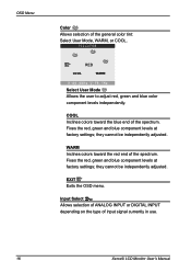
.... Fixes the red, green and blue component levels at factory settings; WARM Inclines colors toward the blue end of input signal currently in use. 16 Xerox© LCD Monitor User's Manual Fixes the red, green and blue component levels at factory settings;
.... Fixes the red, green and blue component levels at factory settings; WARM Inclines colors toward the blue end of input signal currently in use. 16 Xerox© LCD Monitor User's Manual Fixes the red, green and blue component levels at factory settings;
User Manual
Page 18
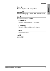
EXIT Exits the OSD menu. ENGLISH OSD Menu Reset Restores all the on all options to the factory settings. OSD Changes the position of the OSD. Language Controls which language is used on -screen menus. Xerox© LCD Monitor User's Manual 17 EXIT Exits the OSD. Position Moves the OSD up and down in the window. Position Moves the OSD left and right in the window. H. V.
EXIT Exits the OSD menu. ENGLISH OSD Menu Reset Restores all the on all options to the factory settings. OSD Changes the position of the OSD. Language Controls which language is used on -screen menus. Xerox© LCD Monitor User's Manual 17 EXIT Exits the OSD. Position Moves the OSD up and down in the window. Position Moves the OSD left and right in the window. H. V.
User Manual
Page 19
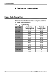
Video signal: (IBM PC/AT) Dot X Line Horizontal Frequency(kHz) 720 x 400 31.47 640 x 480 31.47 37.86 37.50 800 x 600 35.16 37.88 48.08 46.87 1024 x 768 48.36 56.48 60.02 1280 x 1024 63.98 79.98 Vertical Frequency(Hz) 70.00 60.00 72.80 75.00 56.25 60.30 72.20 75.00 60.00 70.10 75.00 60 75 18 Xerox© LCD Monitor User's Manual Technical Information 4 Technical Information Preset Mode Timing Chart The screen image has been optimized during manufacture for the display modes listed below.
Video signal: (IBM PC/AT) Dot X Line Horizontal Frequency(kHz) 720 x 400 31.47 640 x 480 31.47 37.86 37.50 800 x 600 35.16 37.88 48.08 46.87 1024 x 768 48.36 56.48 60.02 1280 x 1024 63.98 79.98 Vertical Frequency(Hz) 70.00 60.00 72.80 75.00 56.25 60.30 72.20 75.00 60.00 70.10 75.00 60 75 18 Xerox© LCD Monitor User's Manual Technical Information 4 Technical Information Preset Mode Timing Chart The screen image has been optimized during manufacture for the display modes listed below.
User Manual
Page 20
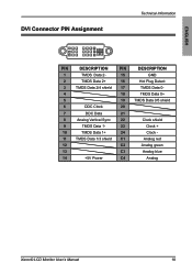
ENGLISH DVI Connector PIN Assignment Technical Information 1 8 C1 C2 9 16 C3 C4 17 24 PIN DESCRIPTION PIN DESCRIPTION 1 TMDS Data 2- 15 GND 2 TMDS Data 2+ 16 Hot Plug Detect 3 TMDS Data 2/4 shield 17 TMDS Data 0- 4 18 TMDS Data 0+ 5 19 TMDS Data 0/5 shield 6 DDC Clock 20 7 DDC Data 21 8 Analog Vertical Sync 22 Clock shield 9 TMDS Data 1- 23 Clock + 10 TMDS Data 1+ 24 Clock - 11 TMDS Data 1/3 shield C1 Analog red 12 C2 Analog green 13 C3 Analog blue 14 +5V Power C4 Analog Xerox© LCD Monitor User's Manual 19
ENGLISH DVI Connector PIN Assignment Technical Information 1 8 C1 C2 9 16 C3 C4 17 24 PIN DESCRIPTION PIN DESCRIPTION 1 TMDS Data 2- 15 GND 2 TMDS Data 2+ 16 Hot Plug Detect 3 TMDS Data 2/4 shield 17 TMDS Data 0- 4 18 TMDS Data 0+ 5 19 TMDS Data 0/5 shield 6 DDC Clock 20 7 DDC Data 21 8 Analog Vertical Sync 22 Clock shield 9 TMDS Data 1- 23 Clock + 10 TMDS Data 1+ 24 Clock - 11 TMDS Data 1/3 shield C1 Analog red 12 C2 Analog green 13 C3 Analog blue 14 +5V Power C4 Analog Xerox© LCD Monitor User's Manual 19

User Manual
Page 21
Sync V. Technical Information D-SUB Connector PIN Assignment 1 6 11 PIN 1 2 3 4 5 6 7 8 9 10 11 12 13 14 15 5 10 15 DESCRIPTION Red Green Blue Ground Self Test Red Ground Green Ground Blue Ground 5 VDC Ground Ground SDA (FOR DDC) H. Sync SCL (FOR DDC) 20 Xerox© LCD Monitor User's Manual
Sync V. Technical Information D-SUB Connector PIN Assignment 1 6 11 PIN 1 2 3 4 5 6 7 8 9 10 11 12 13 14 15 5 10 15 DESCRIPTION Red Green Blue Ground Self Test Red Ground Green Ground Blue Ground 5 VDC Ground Ground SDA (FOR DDC) H. Sync SCL (FOR DDC) 20 Xerox© LCD Monitor User's Manual
User Manual
Page 22
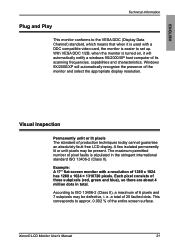
...LCD display. According to ISO 13406-2 (Class II), a maximum of 6 pixels and 7 subpixels may be defective, i. Xerox© LCD Monitor User's Manual 21 With VESA DDC 1/2B, when the monitor is turned on, it is used with a resolution of 1280 x 1024 has 1280 x 1024 = 1310720 pixels. The... maximum permitted number of pixel faults is easier to set up. Example: A 17" flat-screen monitor with a DDC compatible video card, the monitor is stipulated in total. e. This corresponds to approx. 0.002 % of 25 faulted dots. a total of the entire screen surface....
...LCD display. According to ISO 13406-2 (Class II), a maximum of 6 pixels and 7 subpixels may be defective, i. Xerox© LCD Monitor User's Manual 21 With VESA DDC 1/2B, when the monitor is turned on, it is used with a resolution of 1280 x 1024 has 1280 x 1024 = 1310720 pixels. The... maximum permitted number of pixel faults is easier to set up. Example: A 17" flat-screen monitor with a DDC compatible video card, the monitor is stipulated in total. e. This corresponds to approx. 0.002 % of 25 faulted dots. a total of the entire screen surface....

