Owners Manual
Page 7
... 8 Connecting the AC power cord 8 Turning the power on and off 8 Introduction to the DME64N/24N 9 Differences between DME64N/24N 9 DME64N/24N Features 9 Audio System Network 9 Glossary for the DME64N/24N 9 Signal Types 11 System Examples 11 About DME Designer 13 The Controls and Connectors 14 ...51 MIDI Setup (MIDI) Page 51 GPI Setup (GPI) Page 53 Head Amplifier Setup (HA) Page 53 Cascade Setup (CASCAD) Page 55 Check Page 55 Foreword Introduction to the DME64N/24N The Controls and Connectors Preparation Connecting to a Computer Audio I/O Connection Connecting to an External ...
... 8 Connecting the AC power cord 8 Turning the power on and off 8 Introduction to the DME64N/24N 9 Differences between DME64N/24N 9 DME64N/24N Features 9 Audio System Network 9 Glossary for the DME64N/24N 9 Signal Types 11 System Examples 11 About DME Designer 13 The Controls and Connectors 14 ...51 MIDI Setup (MIDI) Page 51 GPI Setup (GPI) Page 53 Head Amplifier Setup (HA) Page 53 Cascade Setup (CASCAD) Page 55 Check Page 55 Foreword Introduction to the DME64N/24N The Controls and Connectors Preparation Connecting to a Computer Audio I/O Connection Connecting to an External ...
Owners Manual
Page 10
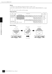
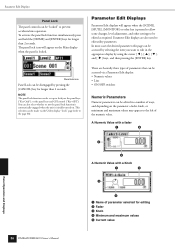
... 1234 5 6 78 NETWORK PEAK MID MASTER SIGNAL IN 1234 5 6 78 PEAK SIGNAL OUT SCENE NUMBER Scene 2 Introduction to 999 scenes can be stored for the DME64N/24N Scene A combination of all configuration and preset parameters is called a "scene." Up to the...
... 1234 5 6 78 NETWORK PEAK MID MASTER SIGNAL IN 1234 5 6 78 PEAK SIGNAL OUT SCENE NUMBER Scene 2 Introduction to 999 scenes can be stored for the DME64N/24N Scene A combination of all configuration and preset parameters is called a "scene." Up to the...

Owners Manual
Page 11
... will occur primarily via the [REMOTE] connector. Type of signals handled by the DME64N/24N Connector [USB] Connector [NETWORK] Connector [MIDI] Connector [GPI] Connector [CASCADE] Connector (DME64N only) [WORD CLOCK] Connector [REMOTE] Connector (Audio I/O Connectors) (DME24N only) (I /O Serial signal transmission/reception channels depends (depending on card. Control signals (MIDI commands) - Control signals between computer...
... will occur primarily via the [REMOTE] connector. Type of signals handled by the DME64N/24N Connector [USB] Connector [NETWORK] Connector [MIDI] Connector [GPI] Connector [CASCADE] Connector (DME64N only) [WORD CLOCK] Connector [REMOTE] Connector (Audio I/O Connectors) (DME24N only) (I /O Serial signal transmission/reception channels depends (depending on card. Control signals (MIDI commands) - Control signals between computer...

Owners Manual
Page 16
.... The open voltage at a TTL level. See "GPI Connection ([GPI] Connectors)" on page 18 for connection details. 16 DME64N/DME24N Owner's Manual Output channels each have a ground screw be sure to connect the DME64N/24N ground screw to only one ground point. Rear ...Panel Rear Panel DME64N 4 67 5 ) The Controls and Connectors 12 DME24N 3 3 9 4 67 5 ...
.... The open voltage at a TTL level. See "GPI Connection ([GPI] Connectors)" on page 18 for connection details. 16 DME64N/DME24N Owner's Manual Output channels each have a ground screw be sure to connect the DME64N/24N ground screw to only one ground point. Rear ...Panel Rear Panel DME64N 4 67 5 ) The Controls and Connectors 12 DME24N 3 3 9 4 67 5 ...

Owners Manual
Page 19
..., turn it on the display: If any scene data has been stored in the following order: audio sources, mixer and/or recorders, and finally power amplifiers. No information will appear...The "NET" page settings must first be transferred to be set up the DME64N/24N operation parameters. Turn power to the "DME Setup Manual" (PDF file) for the ... Remote connection (page 28) MIDI connection(page 30) CASCADE connection(page 31) WORD CLOCK connection(page 32) GPI connection (page 33) 5. See the "Utility Display" section on surge from the DME Designer. To prevent ...
..., turn it on the display: If any scene data has been stored in the following order: audio sources, mixer and/or recorders, and finally power amplifiers. No information will appear...The "NET" page settings must first be transferred to be set up the DME64N/24N operation parameters. Turn power to the "DME Setup Manual" (PDF file) for the ... Remote connection (page 28) MIDI connection(page 30) CASCADE connection(page 31) WORD CLOCK connection(page 32) GPI connection (page 33) 5. See the "Utility Display" section on surge from the DME Designer. To prevent ...

Owners Manual
Page 33
... of 5 volts. The parameters for all GPI input and output connections. GPI Connection IN +V Example: Controlling the DME64N/24N via GPI. NOTE The DME Designer can be used for each GPI input and output are assigned via the DME Designer application. GPI Connection ([GPI] Connectors) GPI Connection ([GPI] Connectors) GPI (General Purpose Interface) device (GPI controller, etc.) can be transferred between...
... of 5 volts. The parameters for all GPI input and output connections. GPI Connection IN +V Example: Controlling the DME64N/24N via GPI. NOTE The DME Designer can be used for each GPI input and output are assigned via the DME Designer application. GPI Connection ([GPI] Connectors) GPI Connection ([GPI] Connectors) GPI (General Purpose Interface) device (GPI controller, etc.) can be transferred between...
Owners Manual
Page 35
...24 parameters can be inverted. When [Parameter Value Edit] is turned ON. : Panel Lock ON (Panel controls locked) Panel Operation and Displays DME64N/DME24N Owner's Manual 35 Six parameters are selected, the display will be used for editing by using the DME Designer application. Buttons are to ... available, and the scroll bar moves one -byte (Roman) characters can be used for each scene. When [Direct Parameter Value], [Scene Change], [GPI Out], or [Play Wav File] are shown on . NOTE User Defined Button settings are common to the device group. 4 Page Scroll Bar...
...24 parameters can be inverted. When [Parameter Value Edit] is turned ON. : Panel Lock ON (Panel controls locked) Panel Operation and Displays DME64N/DME24N Owner's Manual 35 Six parameters are selected, the display will be used for editing by using the DME Designer application. Buttons are to ... available, and the scroll bar moves one -byte (Roman) characters can be used for each scene. When [Direct Parameter Value], [Scene Change], [GPI Out], or [Play Wav File] are shown on . NOTE User Defined Button settings are common to the device group. 4 Page Scroll Bar...
Owners Manual
Page 36
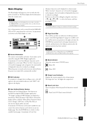
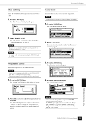
... and hold the [HOME] and [ENTER] keys for editing 2 Fader 3 Knob 4 Minimum and maximum values 5 Current value Panel Operation and Displays 36 DME64N/DME24N Owner's Manual In most cases the desired parameter edit page can be accessed by selecting the item you want to edit in a number of... Edit Displays Panel Lock The panel controls can be set up to lock just the panel keys ("Key Only"), or the panel keys and GPI control ("Key+GPI"). NOTE The panel lock function can be "locked" to prevent accidental mis-operation. Parameter Edit Displays Parameter Edit displays will appear on ....
... and hold the [HOME] and [ENTER] keys for editing 2 Fader 3 Knob 4 Minimum and maximum values 5 Current value Panel Operation and Displays 36 DME64N/DME24N Owner's Manual In most cases the desired parameter edit page can be accessed by selecting the item you want to edit in a number of... Edit Displays Panel Lock The panel controls can be set up to lock just the panel keys ("Key Only"), or the panel keys and GPI control ("Key+GPI"). NOTE The panel lock function can be "locked" to prevent accidental mis-operation. Parameter Edit Displays Parameter Edit displays will appear on ....
Owners Manual
Page 39
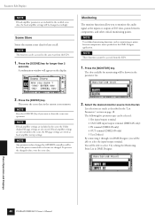
...mute function is used for scene change control by using the DME Designer. There is used to make scene changes from a computer or GPI/MIDI controller connected to be used for longer than 2 seconds. Scenes are muted. Press the [ENTER] key again. Adjust the numeric...Select a new scene. The new scene will be accessed from an ICP1 control panel. 1. The graphic fader provides a visual indication of the DME64N/24N. This function cannot be selected. A confirmation window will appear. Parameter Edit Displays Scene Recall This procedure recalls a new scene (...
...mute function is used for scene change control by using the DME Designer. There is used to make scene changes from a computer or GPI/MIDI controller connected to be used for longer than 2 seconds. Scenes are muted. Press the [ENTER] key again. Adjust the numeric...Select a new scene. The new scene will be accessed from an ICP1 control panel. 1. The graphic fader provides a visual indication of the DME64N/24N. This function cannot be selected. A confirmation window will appear. Parameter Edit Displays Scene Recall This procedure recalls a new scene (...
Owners Manual
Page 40
.../output terminal. The following five position types can be able to select 5 by GPI/MIDI controllers will be accessed from the list. Press the [SCENE] key for later recall...page settings are also stored. Monitoring The monitor functions allow you want to monitor the audio signal at points between components, and other critical monitoring points. The slots available for ...the ICP1. 1. NOTE This function can be selected: 1 Slot input/output terminal 2 CASCADE input/output terminal (DME64N only) 3 IN terminal (DME24N only) 4 OUT terminal (DME24N only) 5 User Defined By ...
.../output terminal. The following five position types can be able to select 5 by GPI/MIDI controllers will be accessed from the list. Press the [SCENE] key for later recall...page settings are also stored. Monitoring The monitor functions allow you want to monitor the audio signal at points between components, and other critical monitoring points. The slots available for ...the ICP1. 1. NOTE This function can be selected: 1 Slot input/output terminal 2 CASCADE input/output terminal (DME64N only) 3 IN terminal (DME24N only) 4 OUT terminal (DME24N only) 5 User Defined By ...

Owners Manual
Page 44
...amplifiers. Current status and selection of the word clock received at the [WORD CLOCK IN] connector. Current status of the DME64N/24N word clock. Sets the minimum calibration value. Current status and setup for display panel contrast. Shows the status of the installed card.... Current status and setup for the panel lock target. Displays the word clock frequency. Displays the audio format - 88.2 or 96 kHz. Current status and setup for connected MIDI devices. GPI connector calibration and status display. Current status and setup for the word clock used to the I ...
...amplifiers. Current status and selection of the word clock received at the [WORD CLOCK IN] connector. Current status of the DME64N/24N word clock. Sets the minimum calibration value. Current status and setup for display panel contrast. Shows the status of the installed card.... Current status and setup for the panel lock target. Displays the word clock frequency. Displays the audio format - 88.2 or 96 kHz. Current status and setup for connected MIDI devices. GPI connector calibration and status display. Current status and setup for the word clock used to the I ...
Owners Manual
Page 48
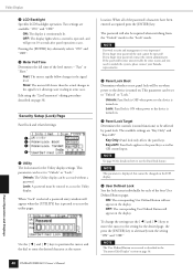
...display settings. The password will go out 10 seconds after panel operation ceases. The available settings are available: "ON," and "OFF." Key+GPI: Panel lock applies to access the utility pages. Panel Operation and Displays Utility Displays 2 LCD Backlight Specifies LCD backlight operation. Pressing...will be set to the "Lock" mode. If you need to enter the desired character at the cursor 48 DME64N/DME24N Owner's Manual location. If you forget your Yamaha representative. 2 Panel Lock Boot Determines whether or not panel lock will appear when the [UTILITY] key is ...
...display settings. The password will go out 10 seconds after panel operation ceases. The available settings are available: "ON," and "OFF." Key+GPI: Panel lock applies to access the utility pages. Panel Operation and Displays Utility Displays 2 LCD Backlight Specifies LCD backlight operation. Pressing...will be set to the "Lock" mode. If you need to enter the desired character at the cursor 48 DME64N/DME24N Owner's Manual location. If you forget your Yamaha representative. 2 Panel Lock Boot Determines whether or not panel lock will appear when the [UTILITY] key is ...
Owners Manual
Page 53
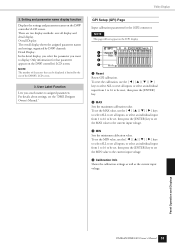
...display, you select the parameter you attach names to assigned parameters. For details about settings, see the "DME Designer Owner's Manual." GPI Setup (GPI) Page Input calibration parameters for that can be set, then press the [ENTER] key to set all display and detail display. ...keys to select ALL to be reset, then press the [ENTER] key. 2 MAX Sets the maximum calibration value. Panel Operation and Displays DME64N/DME24N Owner's Manual 53 Overall Display: The overall display shows the assigned parameter names and settings, organized by the size of characters that parameter...
...display, you select the parameter you attach names to assigned parameters. For details about settings, see the "DME Designer Owner's Manual." GPI Setup (GPI) Page Input calibration parameters for that can be set, then press the [ENTER] key to set all display and detail display. ...keys to select ALL to be reset, then press the [ENTER] key. 2 MAX Sets the maximum calibration value. Panel Operation and Displays DME64N/DME24N Owner's Manual 53 Overall Display: The overall display shows the assigned parameter names and settings, organized by the size of characters that parameter...
Owners Manual
Page 57
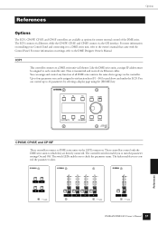
... same device group via the controller. CONTROL PANEL CP4SW 10 10 10 10 0 0 0 0 CONTROL PANEL CP4SF 10 0 CONTROL PANEL CP1SF DME64N/DME24N Owner's Manual 57 Up to four parameter sets can be assigned to the owner's manual that came with the Control Panel. Options References... Options The ICP1, CP4SW, CP1SF, and CP4SF controllers are directly connected. ICP1 This controller connects to DME series units via the GPI interface. You can assign and control any function of the DME series. References CP4SW, CP4SF, and CP1SF These controllers connect to a DME...
... same device group via the controller. CONTROL PANEL CP4SW 10 10 10 10 0 0 0 0 CONTROL PANEL CP4SF 10 0 CONTROL PANEL CP1SF DME64N/DME24N Owner's Manual 57 Up to four parameter sets can be assigned to the owner's manual that came with the Control Panel. Options References... Options The ICP1, CP4SW, CP1SF, and CP4SF controllers are directly connected. ICP1 This controller connects to DME series units via the GPI interface. You can assign and control any function of the DME series. References CP4SW, CP4SF, and CP1SF These controllers connect to a DME...

Owners Manual
Page 61
...8226; If neither of the above is the problem, contact your Yamaha service center or representative. Cannot exchange data between the DME64N/24N and the DME Designer. Use Defined Button settings... ON (page 39)? • Have you used DME Designer to select a scene that does not output audio? • Are you using a version of DME Designer later than 3.0? • Are the cables connected... to check the MIDI Program Change Table settings. • Use the DME Designer to check the GPI input assignments. • Use the DME Designer to check the Remote Control Setup List assignments. &#...
...8226; If neither of the above is the problem, contact your Yamaha service center or representative. Cannot exchange data between the DME64N/24N and the DME Designer. Use Defined Button settings... ON (page 39)? • Have you used DME Designer to select a scene that does not output audio? • Are you using a version of DME Designer later than 3.0? • Are the cables connected... to check the MIDI Program Change Table settings. • Use the DME Designer to check the GPI input assignments. • Use the DME Designer to check the Remote Control Setup List assignments. &#...
Owners Manual
Page 64
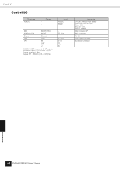
Control I/O Control I/O Terminals REMOTE Format - Level RS232C RS422 MIDI WORDCLOCK Ethernet USB GPI IN/OUT/THRU IN/OUT Ethernet USB IN OUT +V DME64N: 16-GPI inputs and 16-GPI outputs DME24N: 8-GPI inputs and 8-GPI outputs Outputs: Imax/pin = 16mA Outputs: VH = 2.5V(min.), VL = 0.6V(max.) TTL/75Ω 0 - 3.3V 0 - 5V TTL 5V Connector D-SUB Connector 9-pin (Male) Baud Rate = 38,400 bps Data = 8bit Stop bit = 1bit PARITY = NON DIN Connector 5P BNC Connector RJ-45 USB Type B (Female) Euroblock Connector References 64 DME64N/DME24N Owner's Manual
Control I/O Control I/O Terminals REMOTE Format - Level RS232C RS422 MIDI WORDCLOCK Ethernet USB GPI IN/OUT/THRU IN/OUT Ethernet USB IN OUT +V DME64N: 16-GPI inputs and 16-GPI outputs DME24N: 8-GPI inputs and 8-GPI outputs Outputs: Imax/pin = 16mA Outputs: VH = 2.5V(min.), VL = 0.6V(max.) TTL/75Ω 0 - 3.3V 0 - 5V TTL 5V Connector D-SUB Connector 9-pin (Male) Baud Rate = 38,400 bps Data = 8bit Stop bit = 1bit PARITY = NON DIN Connector 5P BNC Connector RJ-45 USB Type B (Female) Euroblock Connector References 64 DME64N/DME24N Owner's Manual

Owners Manual
Page 73
... processor) Ethernet Ethersound Euroblock GPI (General Purpose Interface) Initial Settings MAC (Media Access Control) Address MIDI (Musical Instrument Digital Interface) Mini YGDAI (Yamaha General Digital Audio Interface) card Explanations A ...DME64N/24N via external devices and custom-made via a Euroblock connector. Yamaha cascade connections employ half-pitch 68-pin D-Sub connectors. Several categories are specified according to electrical characteristics, with higher category numbers denoting higher quality cable. It transmits uncompressed digital audio signals via GPI...
... processor) Ethernet Ethersound Euroblock GPI (General Purpose Interface) Initial Settings MAC (Media Access Control) Address MIDI (Musical Instrument Digital Interface) Mini YGDAI (Yamaha General Digital Audio Interface) card Explanations A ...DME64N/24N via external devices and custom-made via a Euroblock connector. Yamaha cascade connections employ half-pitch 68-pin D-Sub connectors. Several categories are specified according to electrical characteristics, with higher category numbers denoting higher quality cable. It transmits uncompressed digital audio signals via GPI...

Owners Manual
Page 75
...96kHz] [88.2kHz] [48kHz] [44.1kHz] Indicator 14 A [AC IN] Connector 16 ADAT (Alesis Digital Audio Tape) (Glossary 70 AES/EBU (Audio Engineering Society/European Broadcasting Union) (Glossary 70 area 9 audio 11 B Band Output Level 40 Battery 45 BNC (Bayonet Nut Connector, or Bayonet Neill Concelman) (Glossary 70 C...GPI (General Purpose Interface) (Glossary 70 GPI connection 32 [GPI] Connector 16, 32 Ground Screw 16 H HA 52 HA Page 52 Head Amplifier Setup (HA) Page 52, 54 Head Margin 54 High-pass Filter 53 High-pass Filter Frequency 53 [HOME] Button 15 Host 50 HPF 53 DME64N/...
...96kHz] [88.2kHz] [48kHz] [44.1kHz] Indicator 14 A [AC IN] Connector 16 ADAT (Alesis Digital Audio Tape) (Glossary 70 AES/EBU (Audio Engineering Society/European Broadcasting Union) (Glossary 70 area 9 audio 11 B Band Output Level 40 Battery 45 BNC (Bayonet Nut Connector, or Bayonet Neill Concelman) (Glossary 70 C...GPI (General Purpose Interface) (Glossary 70 GPI connection 32 [GPI] Connector 16, 32 Ground Screw 16 H HA 52 HA Page 52 Head Amplifier Setup (HA) Page 52, 54 Head Margin 54 High-pass Filter 53 High-pass Filter Frequency 53 [HOME] Button 15 Host 50 HPF 53 DME64N/...
Owners Manual
Page 76
...MIDI THRU] Connectors .......... 17 [MIDI] Indicator 15 MIDI Page 50 MIDI Setup (MIDI) Page 50 MIN 52 Mini YGDAI (Yamaha General Digital Audio Interface) card (Glossary 70 Misc Page 48 Miscellaneous Setup (Misc) Page 48 Mixer I/O 54 [MONITOR] Button 15 Monitoring 39... Program Change 50 R rear panel 16 Remote (Misc Page 48 Remote Connection 28 [REMOTE] Connector 17, 28 Reset (GPI Page 52 Reset (Slot Page 49 RJ-45 (Glossary 71 router (Glossary 71 RS-232C (Glossary 71 RS-422 (... [SIGNAL] Indicator 15 Slot Information (Slot) Page 49 Slot Page 49 76 DME64N/DME24N Owner's Manual
...MIDI THRU] Connectors .......... 17 [MIDI] Indicator 15 MIDI Page 50 MIDI Setup (MIDI) Page 50 MIN 52 Mini YGDAI (Yamaha General Digital Audio Interface) card (Glossary 70 Misc Page 48 Miscellaneous Setup (Misc) Page 48 Mixer I/O 54 [MONITOR] Button 15 Monitoring 39... Program Change 50 R rear panel 16 Remote (Misc Page 48 Remote Connection 28 [REMOTE] Connector 17, 28 Reset (GPI Page 52 Reset (Slot Page 49 RJ-45 (Glossary 71 router (Glossary 71 RS-232C (Glossary 71 RS-422 (... [SIGNAL] Indicator 15 Slot Information (Slot) Page 49 Slot Page 49 76 DME64N/DME24N Owner's Manual