

Owners Manual
Page 5
GUARD (memory guard) ...44 INTRODUCTION CONTROLS AND FUNCTIONS ...4 Front panel ...4 Remote control ...6 Using the remote control ...7 Front panel display ...8 PREPARATION PREPARATION SPEAKER SETUP ...9 Speakers ...9 Speaker placement ...9 Connecting the speakers ...10 CONNECTIONS ...13 Before connecting components ...13 Connecting video components ...14 Connecting audio components ...16 Connecting the antennas ...17 ...
GUARD (memory guard) ...44 INTRODUCTION CONTROLS AND FUNCTIONS ...4 Front panel ...4 Remote control ...6 Using the remote control ...7 Front panel display ...8 PREPARATION PREPARATION SPEAKER SETUP ...9 Speakers ...9 Speaker placement ...9 Connecting the speakers ...10 CONNECTIONS ...13 Before connecting components ...13 Connecting video components ...14 Connecting audio components ...16 Connecting the antennas ...17 ...

Owners Manual
Page 13
...placement Refer to the following diagram when you connect speakers to. APPENDIX CAUTION Use magnetically shielded speakers. English 9 PREPARATION SPEAKER SETUP INTRODUCTION Speakers This unit has been designed to provide the best soundfield quality with the monitor, place the speakers away from ...Main speaker (L) 1.8 m (6 feet) Rear speaker (L) I Main speakers Place the main left and right speakers and a center speaker. The YAMAHA Active Servo Processing Subwoofer System is for reproducing the LFE (low-frequency effect) channel with the front face of the room to use the models...
...placement Refer to the following diagram when you connect speakers to. APPENDIX CAUTION Use magnetically shielded speakers. English 9 PREPARATION SPEAKER SETUP INTRODUCTION Speakers This unit has been designed to provide the best soundfield quality with the monitor, place the speakers away from ...Main speaker (L) 1.8 m (6 feet) Rear speaker (L) I Main speakers Place the main left and right speakers and a center speaker. The YAMAHA Active Servo Processing Subwoofer System is for reproducing the LFE (low-frequency effect) channel with the front face of the room to use the models...

Owners Manual
Page 14
... ridge. 1 1 2 Remove approximately 10 mm (3/8") of this unit and/ or the speakers. I REAR SPEAKERS terminals A rear speaker system can be connected to these terminals. SPEAKER SETUP Connecting the speakers Be sure to these terminals.
... ridge. 1 1 2 Remove approximately 10 mm (3/8") of this unit and/ or the speakers. I REAR SPEAKERS terminals A rear speaker system can be connected to these terminals. SPEAKER SETUP Connecting the speakers Be sure to these terminals.
Owners Manual
Page 15
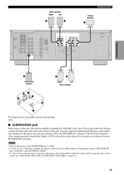
... to adjust its volume level. It is decoded are directed to this jack in accordance with built-in amplifier, including the YAMAHA Active Servo Processing Subwoofer System, connect the input jack of SPEAKER SET item "1D BASS" on the SET MENU to MAIN...4 Subwoofer system 5 Right 6 Left Rear speaker 3 2 1 4 5 6 The diagram shows the speaker layout in accordance with your SPEAKER SET selections. SPEAKER SETUP Main speaker Right Left Center speaker 1 2 INTRODUCTION 3 SPEAKERS DIGITAL INPUT COAXIAL CD SURROUND V-AUX MAIN 6CH INPUT AUDIO VIDEO R L VIDEO R TUNER AM ANT...
... to adjust its volume level. It is decoded are directed to this jack in accordance with built-in amplifier, including the YAMAHA Active Servo Processing Subwoofer System, connect the input jack of SPEAKER SET item "1D BASS" on the SET MENU to MAIN...4 Subwoofer system 5 Right 6 Left Rear speaker 3 2 1 4 5 6 The diagram shows the speaker layout in accordance with your SPEAKER SET selections. SPEAKER SETUP Main speaker Right Left Center speaker 1 2 INTRODUCTION 3 SPEAKERS DIGITAL INPUT COAXIAL CD SURROUND V-AUX MAIN 6CH INPUT AUDIO VIDEO R L VIDEO R TUNER AM ANT...

Owners Manual
Page 16
... impedance must be 8 Ω or higher. IMPEDANCE SELECTOR SET BEFORE POWER ON MAIN CENTER REAR : 8ΩMIN. /SPEAKER : 8ΩMIN. /SPEAKER : 8ΩMIN. /SPEAKER (U.S.A. SPEAKER SETUP I IMPEDANCE SELECTOR switch WARNING Do not change setting of the IMPEDANCE SELECTOR switch when the power of this unit is on when STANDBY/ON (or...
... impedance must be 8 Ω or higher. IMPEDANCE SELECTOR SET BEFORE POWER ON MAIN CENTER REAR : 8ΩMIN. /SPEAKER : 8ΩMIN. /SPEAKER : 8ΩMIN. /SPEAKER (U.S.A. SPEAKER SETUP I IMPEDANCE SELECTOR switch WARNING Do not change setting of the IMPEDANCE SELECTOR switch when the power of this unit is on when STANDBY/ON (or...

Owners Manual
Page 44
... items require extra steps. 1 HP TONE CTRL BASS/TRBL 0 dB I/O ASSIGN C (optical input) D (coaxial input) (1) DVD (2) CD AUTO 0 OFF Press SET MENU to enter the setup mode of 10 items including the speaker mode setting. Items 1 SPEAKER SET A CENTER B MAIN C REAR LR D BASS E MAIN Lv LFE LEVEL SP/HP SP DLY...
... items require extra steps. 1 HP TONE CTRL BASS/TRBL 0 dB I/O ASSIGN C (optical input) D (coaxial input) (1) DVD (2) CD AUTO 0 OFF Press SET MENU to enter the setup mode of 10 items including the speaker mode setting. Items 1 SPEAKER SET A CENTER B MAIN C REAR LR D BASS E MAIN Lv LFE LEVEL SP/HP SP DLY...


