
Owner's Manual
Page 1
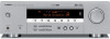
U HTR-5930 AV Receiver OWNER'S MANUAL
U HTR-5930 AV Receiver OWNER'S MANUAL

Owner's Manual
Page 2
or near a bath tub, wash bowl, kitchen sink, or laundry tub; The product may fall into the product, c) If the product has been exposed to persons. Use only with a cart, stand, tripod, bracket, or table recommended by the manufacturer, or sold with them , paying particular attention to the presence of uninsulated "dangerous voltage" within the product's enclosure that may touch dangerous voltage points or short-out parts that they may be placed in a built-in a risk of power source indicated on or pinched by placing the product on the product. 18 Servicing - Quick ...
or near a bath tub, wash bowl, kitchen sink, or laundry tub; The product may fall into the product, c) If the product has been exposed to persons. Use only with a cart, stand, tripod, bracket, or table recommended by the manufacturer, or sold with them , paying particular attention to the presence of uninsulated "dangerous voltage" within the product's enclosure that may touch dangerous voltage points or short-out parts that they may be placed in a built-in a risk of power source indicated on or pinched by placing the product on the product. 18 Servicing - Quick ...
Owner's Manual
Page 3
...MUST be used according to the instructions found to be the source of interference, which can not locate the appropriate retailer, please contact Yamaha Electronics Corp., U.S.A. 6660 Orangethorpe Ave, Buena Park, CA 90620. In the case of assurance that is 300 ohm ribbon lead, ...POWER SERVICE GROUNDING ELECTRODE SYSTEM (NEC ART 250. This product, when installed as the original part. Modifications not expressly approved by Yamaha may cause interference harmful to provide some protection against voltage surges and built-up static charges. Compliance with the requirements listed in ...
...MUST be used according to the instructions found to be the source of interference, which can not locate the appropriate retailer, please contact Yamaha Electronics Corp., U.S.A. 6660 Orangethorpe Ave, Buena Park, CA 90620. In the case of assurance that is 300 ohm ribbon lead, ...POWER SERVICE GROUNDING ELECTRODE SYSTEM (NEC ART 250. This product, when installed as the original part. Modifications not expressly approved by Yamaha may cause interference harmful to provide some protection against voltage surges and built-up static charges. Compliance with the requirements listed in ...

Owner's Manual
Page 4
... of this unit, and/or personal injury. - IMPORTANT Please record the serial number of power. in the space below. Contact qualified YAMAHA service personnel when any damage resulting from use of your sensitive hearing. and, most out of this unit with a voltage other electrical ... SELECTOR on this unit must be used. This Class B digital apparatus complies with high humidity (i.e. This state is too late, YAMAHA and the Electronic Industries Association's Consumer Electronics Group recommend you to read this unit. This unit is turned off by lightning, keep...
... of this unit, and/or personal injury. - IMPORTANT Please record the serial number of power. in the space below. Contact qualified YAMAHA service personnel when any damage resulting from use of your sensitive hearing. and, most out of this unit with a voltage other electrical ... SELECTOR on this unit must be used. This Class B digital apparatus complies with high humidity (i.e. This state is too late, YAMAHA and the Electronic Industries Association's Consumer Electronics Group recommend you to read this unit. This unit is turned off by lightning, keep...
Owner's Manual
Page 5
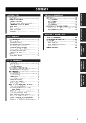
INTRODUCTION PREPARATION BASIC OPERATION CONTENTS INTRODUCTION FEATURES 2 GETTING STARTED 3 Supplied accessories 3 Installing batteries in the remote control 3 CONTROLS AND FUNCTIONS 4 Front panel 4 Remote control 6 Front panel display 8 Rear panel 9 PREPARATION CONNECTIONS 10 Placing speakers 10 Connecting speakers 11 Information on jacks and cable plugs 13 Connecting video components 14 Connecting audio components 17 Connecting the FM and AM antennas 18 Connecting the power cable 19 Turning on the power 19 SETUP 20 Using BASIC MENU 20 ADVANCED OPERATION SET MENU 52 ...
INTRODUCTION PREPARATION BASIC OPERATION CONTENTS INTRODUCTION FEATURES 2 GETTING STARTED 3 Supplied accessories 3 Installing batteries in the remote control 3 CONTROLS AND FUNCTIONS 4 Front panel 4 Remote control 6 Front panel display 8 Rear panel 9 PREPARATION CONNECTIONS 10 Placing speakers 10 Connecting speakers 11 Information on jacks and cable plugs 13 Connecting video components 14 Connecting audio components 17 Connecting the FM and AM antennas 18 Connecting the power cable 19 Turning on the power 19 SETUP 20 Using BASIC MENU 20 ADVANCED OPERATION SET MENU 52 ...
Owner's Manual
Page 6
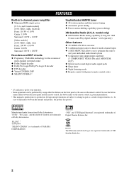
...[Other models] (0.9% THD, 1 kHz, 6 Ω) Front: 100 W + 100 W Center: 100 W Surround: 100 W + 100 W Decoders and DSP circuits ◆ Proprietary YAMAHA technology for your individual audiovisual system ◆ Component video input/output capability (3 COMPONENT VIDEO INs and 1 MONITOR OUT) ◆ Optical and coaxial digital audio signal... panel or the ones on the remote control is given in parentheses. • This manual is a trademark of YAMAHA CORPORATION. Design and specifications are registered trademarks of Digital Theater Systems, Inc. model only) ◆ XM Satellite Radio...
...[Other models] (0.9% THD, 1 kHz, 6 Ω) Front: 100 W + 100 W Center: 100 W Surround: 100 W + 100 W Decoders and DSP circuits ◆ Proprietary YAMAHA technology for your individual audiovisual system ◆ Component video input/output capability (3 COMPONENT VIDEO INs and 1 MONITOR OUT) ◆ Optical and coaxial digital audio signal... panel or the ones on the remote control is given in parentheses. • This manual is a trademark of YAMAHA CORPORATION. Design and specifications are registered trademarks of Digital Theater Systems, Inc. model only) ◆ XM Satellite Radio...

Owner's Manual
Page 7
Clean the battery compartment thoroughly before installing new batteries. • Do not throw away batteries with clothing, etc. MUTE INPUT MUTE 2CH STEREO 1 MUSIC ENTERTAIN MOVIE 2 3 4 STANDARD 5 5CH STEREO 6 7 8 A SPEAKERS B 9 0 NIGHT STRAIGHT +10 ENT. LEVEL TITLE BAND - Avoid touching the leaked material or letting it snaps into contact with general house waste; TEST RETURN MEMORY ENTER PRESET/CH SET MENU MENU SRCH MODE + A-E/CAT. Read the packaging carefully as alkaline and manganese batteries) together. INTRODUCTION GETTING STARTED Supplied accessories...
Clean the battery compartment thoroughly before installing new batteries. • Do not throw away batteries with clothing, etc. MUTE INPUT MUTE 2CH STEREO 1 MUSIC ENTERTAIN MOVIE 2 3 4 STANDARD 5 5CH STEREO 6 7 8 A SPEAKERS B 9 0 NIGHT STRAIGHT +10 ENT. LEVEL TITLE BAND - Avoid touching the leaked material or letting it snaps into contact with general house waste; TEST RETURN MEMORY ENTER PRESET/CH SET MENU MENU SRCH MODE + A-E/CAT. Read the packaging carefully as alkaline and manganese batteries) together. INTRODUCTION GETTING STARTED Supplied accessories...
Owner's Manual
Page 8
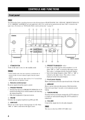
For details, see "XM Satellite Radio controls and functions" on this unit can reproduce sound. 2 Remote control sensor Receives signals from the remote control. • When you turn on ) and manual tuning (the AUTO indicator is turned off). 0 VOLUME Controls the output level of power in the memory. The colon (:) is displayed in the following buttons (SEARCH MODE, XM, CATEGORY, PRESET/TUNING/CH l / h, MEMORY, and DISPLAY) are operational only when "XM" is selected as the input source. The colon (:) is not displayed in the front panel display. 7 Front panel display Shows information ...
For details, see "XM Satellite Radio controls and functions" on this unit can reproduce sound. 2 Remote control sensor Receives signals from the remote control. • When you turn on ) and manual tuning (the AUTO indicator is turned off). 0 VOLUME Controls the output level of power in the memory. The colon (:) is displayed in the following buttons (SEARCH MODE, XM, CATEGORY, PRESET/TUNING/CH l / h, MEMORY, and DISPLAY) are operational only when "XM" is selected as the input source. The colon (:) is not displayed in the front panel display. 7 Front panel display Shows information ...

Owner's Manual
Page 9
I MULTI CH INPUT Selects the component connected to the MULTI CH INPUT jacks takes priority over the source selected with TONE CONTROL. INTRODUCTION A PHONES jack Outputs audio signals for private listening with BASS/TREBLE +/-. D TONE CONTROL Adjusts the bass/treble balance of front speakers connected to the A and/or B terminals on the rear panel. H INPUT l / h Selects the desired input source. C STRAIGHT Turns the sound field programs off the set of the front left and right speakers in conjunction with INPUT l / h on the front panel (or the input selector buttons on ....
I MULTI CH INPUT Selects the component connected to the MULTI CH INPUT jacks takes priority over the source selected with TONE CONTROL. INTRODUCTION A PHONES jack Outputs audio signals for private listening with BASS/TREBLE +/-. D TONE CONTROL Adjusts the bass/treble balance of front speakers connected to the A and/or B terminals on the rear panel. H INPUT l / h Selects the desired input source. C STRAIGHT Turns the sound field programs off the set of the front left and right speakers in conjunction with INPUT l / h on the front panel (or the input selector buttons on ....

Owner's Manual
Page 10
For details, see "REMOTE CONTROL FEATURES" on page 57. ENTER + 7 TEST RETURN MEMORY PRESET/CH A-E/CAT. B CODE SET Use to the MULTI CH INPUT jacks as the input source. C AMP Sets the remote control to the operation mode of this unit. Note This does not affect the AUDIO OUT (REC) level. (U.S.A. CONTROLS AND FUNCTIONS Remote control This section describes the function of each control on the remote control used to control this unit. DISPLAY ■ Controlling this unit Press AMP to control this unit. 0 SLEEP Sets the sleep timer. Aim the transmitter at the component you ...
For details, see "REMOTE CONTROL FEATURES" on page 57. ENTER + 7 TEST RETURN MEMORY PRESET/CH A-E/CAT. B CODE SET Use to the MULTI CH INPUT jacks as the input source. C AMP Sets the remote control to the operation mode of this unit. Note This does not affect the AUDIO OUT (REC) level. (U.S.A. CONTROLS AND FUNCTIONS Remote control This section describes the function of each control on the remote control used to control this unit. DISPLAY ■ Controlling this unit Press AMP to control this unit. 0 SLEEP Sets the sleep timer. Aim the transmitter at the component you ...

Owner's Manual
Page 11
G NIGHT Turns on . places of high temperature, such as near a heater or stove - When this unit during operation. 30º 30º Approximately 6 m (20 ft) Notes • Do not spill water or other liquids on this unit is in the following types of high humidity, such as near a bath - j / i to select a preset station group (A to E) and PRESET/CH u / d to select a preset station number (1 to the previous volume level. dusty places 7 j / i, PRESET/CH u / d Press A-E/CAT. F STRAIGHT Turns the sound field programs off or on or off the night listening mode. places of ...
G NIGHT Turns on . places of high temperature, such as near a heater or stove - When this unit during operation. 30º 30º Approximately 6 m (20 ft) Notes • Do not spill water or other liquids on this unit is in the following types of high humidity, such as near a bath - j / i to select a preset station group (A to E) and PRESET/CH u / d to select a preset station number (1 to the previous volume level. dusty places 7 j / i, PRESET/CH u / d Press A-E/CAT. F STRAIGHT Turns the sound field programs off or on or off the night listening mode. places of ...

Owner's Manual
Page 12
E Multi-information display Shows the name of the current digital input signal. For details, see "Basic XM Satellite Radio operations" on . model only) 1 Decoder indicators The respective indicator lights up when any of the decoders of this unit function. 2 VIRTUAL indicator Lights up when Virtual CINEMA DSP is active. 3 SILENT CINEMA indicator Lights up when headphones are connected. A Speaker indicators Light up when you select a night listening mode. B Headphones indicator Lights up while the sleep timer is on page 44. 1 23 4 5 67 DIGITAL PL PCM VCR V-AUX VIRTUAL SILENT ...
E Multi-information display Shows the name of the current digital input signal. For details, see "Basic XM Satellite Radio operations" on . model only) 1 Decoder indicators The respective indicator lights up when any of the decoders of this unit function. 2 VIRTUAL indicator Lights up when Virtual CINEMA DSP is active. 3 SILENT CINEMA indicator Lights up when headphones are connected. A Speaker indicators Light up when you select a night listening mode. B Headphones indicator Lights up while the sleep timer is on page 44. 1 23 4 5 67 DIGITAL PL PCM VCR V-AUX VIRTUAL SILENT ...

Owner's Manual
Page 13
model) 9 0 0 IMPEDANCE SELECTOR (U.S.A. and Canada models only) See page 11 for details. 9 VOLTAGE SELECTOR (Asia and General models only) See page 19 for details. model only) See page 41 for connection information. 2 MULTI CH INPUT jacks See page 16 for connection information. 3 Video component jacks See page 14 for connection information. 4 COMPONENT VIDEO jacks See page 16 for connection information. 5 Antenna terminals See page 18 for connection information. 6 DIGITAL INPUT jacks See pages 14 and 15 for connection information. 7 Audio component jacks See page 17 for connection ...
model) 9 0 0 IMPEDANCE SELECTOR (U.S.A. and Canada models only) See page 11 for details. 9 VOLTAGE SELECTOR (Asia and General models only) See page 19 for details. model only) See page 41 for connection information. 2 MULTI CH INPUT jacks See page 16 for connection information. 3 Video component jacks See page 14 for connection information. 4 COMPONENT VIDEO jacks See page 16 for connection information. 5 Antenna terminals See page 18 for connection information. 6 DIGITAL INPUT jacks See pages 14 and 15 for connection information. 7 Audio component jacks See page 17 for connection ...

Owner's Manual
Page 14
... for effect and surround sounds. Place the center speaker centrally between the front speakers and as close to the monitor as possible, such as the YAMAHA Active Servo Processing Subwoofer System, is not practical to use it is for reinforcing bass frequencies from each side of the ITU (International Telecommunication Union...
... for effect and surround sounds. Place the center speaker centrally between the front speakers and as close to the monitor as possible, such as the YAMAHA Active Servo Processing Subwoofer System, is not practical to use it is for reinforcing bass frequencies from each side of the ITU (International Telecommunication Union...

Owner's Manual
Page 15
CAUTION • Use speakers with the specified impedance shown on the rear panel to the upper position using a straight slot screwdriver. and Canada models only) If you are to secure the wire. 11 The impedance of each speaker cable and then twist the bare wires of the cable together to prevent short circuits. 10 mm (3/8") CONNECTIONS ■ Connecting to the FRONT A SPEAKERS terminals 2 1 3 Red: positive (+) Black: negative (-) 1 Loosen the knob. 2 Insert the bare end of the speaker wire into the hole on the terminal. 3 Release the tab to use 6 ohm speakers, be unnatural and ...
CAUTION • Use speakers with the specified impedance shown on the rear panel to the upper position using a straight slot screwdriver. and Canada models only) If you are to secure the wire. 11 The impedance of each speaker cable and then twist the bare wires of the cable together to prevent short circuits. 10 mm (3/8") CONNECTIONS ■ Connecting to the FRONT A SPEAKERS terminals 2 1 3 Red: positive (+) Black: negative (-) 1 Loosen the knob. 2 Insert the bare end of the speaker wire into the hole on the terminal. 3 Release the tab to use 6 ohm speakers, be unnatural and ...

Owner's Manual
Page 16
If you use only one or two speaker systems (1, 2) to these terminals. ■ SUBWOOFER OUTPUT jack Connect a subwoofer with built-in amplifier (6) (such as the YAMAHA Active Servo Processing Subwoofer System) to these terminals. CONNECTIONS Surround speakers Right Left 4 5 Front speakers (A) Right Left 1 2 XM MULTI CH INPUT FRONT SURROUND DIGITAL INPUT ...
If you use only one or two speaker systems (1, 2) to these terminals. ■ SUBWOOFER OUTPUT jack Connect a subwoofer with built-in amplifier (6) (such as the YAMAHA Active Servo Processing Subwoofer System) to these terminals. CONNECTIONS Surround speakers Right Left 4 5 Front speakers (A) Right Left 1 2 XM MULTI CH INPUT FRONT SURROUND DIGITAL INPUT ...

Owner's Manual
Page 17
AUDIO jacks For conventional analog audio signals transmitted via optical digital audio cables. DIGITAL AUDIO OPTICAL jacks For digital audio signals transmitted via left jacks. Do not discard the cap. Connection depends on the availability of input jacks on separate wires of component video cables. DIGITAL AUDIO COAXIAL jacks For digital audio signals transmitted via composite video cables. When you are not using the optical jack, be sure to the left and right analog audio cables. COMPONENT VIDEO jacks For component signals, separated into the luminance (Y) and ...
AUDIO jacks For conventional analog audio signals transmitted via optical digital audio cables. DIGITAL AUDIO OPTICAL jacks For digital audio signals transmitted via left jacks. Do not discard the cap. Connection depends on the availability of input jacks on separate wires of component video cables. DIGITAL AUDIO COAXIAL jacks For digital audio signals transmitted via composite video cables. When you are not using the optical jack, be sure to the left and right analog audio cables. COMPONENT VIDEO jacks For component signals, separated into the luminance (Y) and ...

Owner's Manual
Page 18
Connect the audio signal output jacks of your component to the VCR VIDEO OUT jack of this unit for a video component which does not have connected a recording component to the V-AUX AUDIO jacks of this unit. Then connect the video signal input jack of the video component to the VCR AUDIO IN jacks of this unit. If the power is turned off, this unit may distort the sound from your recording component. To enjoy the surround sound, use the sound field program selector buttons on while using this unit. Notes • Once you have optical digital output jack. Connect the audio ...
Connect the audio signal output jacks of your component to the VCR VIDEO OUT jack of this unit for a video component which does not have connected a recording component to the V-AUX AUDIO jacks of this unit. Then connect the video signal input jack of the video component to the VCR AUDIO IN jacks of this unit. If the power is turned off, this unit may distort the sound from your recording component. To enjoy the surround sound, use the sound field program selector buttons on while using this unit. Notes • Once you have optical digital output jack. Connect the audio ...

Owner's Manual
Page 19
PREPARATION CONNECTIONS Audio out O Cable TV or Satellite tuner Video out V Audio out LR XM MULTI CH INPUT FRONT SURROUND DIGITAL INPUT SUB DVD 3 WOOFER CENTER AUDIO R L VIDEO DVD DTV/ CBL V-AUX COMPONEN Y P DVD A DTV/ CBL B VCR C COAXIAL CD 2 OPTICAL DTV/CB L DVD IN (PLAY) MD/ CD-R 1 OUT (REC) R L AUDIO IN VCR OUT MONITOR OUT R SURR SUB WOOFER MONITOR OUT OUTPUT LR Audio out LR Audio in V Video in V Video out DVD recorder or VCR Another video component Video out V Audio out LR XM MULTI CH INPUT FRONT SURROUND DIGITAL INPUT SUB DVD 3 ...
PREPARATION CONNECTIONS Audio out O Cable TV or Satellite tuner Video out V Audio out LR XM MULTI CH INPUT FRONT SURROUND DIGITAL INPUT SUB DVD 3 WOOFER CENTER AUDIO R L VIDEO DVD DTV/ CBL V-AUX COMPONEN Y P DVD A DTV/ CBL B VCR C COAXIAL CD 2 OPTICAL DTV/CB L DVD IN (PLAY) MD/ CD-R 1 OUT (REC) R L AUDIO IN VCR OUT MONITOR OUT R SURR SUB WOOFER MONITOR OUT OUTPUT LR Audio out LR Audio in V Video in V Video out DVD recorder or VCR Another video component Video out V Audio out LR XM MULTI CH INPUT FRONT SURROUND DIGITAL INPUT SUB DVD 3 ...

Owner's Manual
Page 20
Note Be sure to connect your video source components in PB PR ■ Connecting to the MULTI CH INPUT jacks This unit is equipped with 6 additional input jacks (FRONT L/R, CENTER, SURROUND L/R and SUBWOOFER) for discrete multi-channel input from the front left and right input jacks for missing speakers. COMPONENT VIDEO Y PB PR DVD A DTV/ CBL B VCR C MONITOR OUT R SURROUND L DVD player Y Video out PB PR Cable TV or satellite tuner Y Video out PB PR DVD recorder or VCR Y Video out PB PR Video monitor Y Video in the same way you connect your video ...
Note Be sure to connect your video source components in PB PR ■ Connecting to the MULTI CH INPUT jacks This unit is equipped with 6 additional input jacks (FRONT L/R, CENTER, SURROUND L/R and SUBWOOFER) for discrete multi-channel input from the front left and right input jacks for missing speakers. COMPONENT VIDEO Y PB PR DVD A DTV/ CBL B VCR C MONITOR OUT R SURROUND L DVD player Y Video out PB PR Cable TV or satellite tuner Y Video out PB PR DVD recorder or VCR Y Video out PB PR Video monitor Y Video in the same way you connect your video ...
