

Owner's Manual
Page 1
U HTR-6050 AV Receiver OWNER'S MANUAL
U HTR-6050 AV Receiver OWNER'S MANUAL
Owner's Manual
Page 2
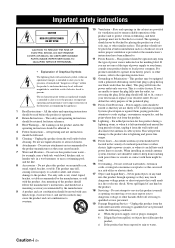
NO USER-SERVICEABLE PARTS INSIDE. The safety and operating instructions should never be retained for example, near a swimming pool; Unplug this product near water - Do not use this product from touching such power lines or circuits as this product yourself as they may touch dangerous voltage points or short-out parts that may expose you to the presence of power source indicated on the product. 18 Servicing - for future reference. 3 Heed Warnings - Use only with a cart, stand, tripod, bracket, or table recommended by items placed upon or against them might be operated ...
NO USER-SERVICEABLE PARTS INSIDE. The safety and operating instructions should never be retained for example, near a swimming pool; Unplug this product near water - Do not use this product from touching such power lines or circuits as this product yourself as they may touch dangerous voltage points or short-out parts that may expose you to the presence of power source indicated on the product. 18 Servicing - for future reference. 3 Heed Warnings - Use only with a cart, stand, tripod, bracket, or table recommended by items placed upon or against them might be operated ...

Owner's Manual
Page 3
...characteristics as close to those controls that your use of interference, which can not locate the appropriate retailer, please contact Yamaha Electronics Corp., U.S.A. 6660 Orangethorpe Ave., Buena Park, CA 90620. Adjust only those products distributed by the interference. Modifications not expressly ...will not occur in the USA. 3 NOTE: This product has been tested and found to determine that is being affected by Yamaha Corporation of cable entry as indicated in the instructions contained in harmful interference with these corrective measures do not produce satisfactory results, ...
...characteristics as close to those controls that your use of interference, which can not locate the appropriate retailer, please contact Yamaha Electronics Corp., U.S.A. 6660 Orangethorpe Ave., Buena Park, CA 90620. Adjust only those products distributed by the interference. Modifications not expressly ...will not occur in the USA. 3 NOTE: This product has been tested and found to determine that is being affected by Yamaha Corporation of cable entry as indicated in the instructions contained in harmful interference with these corrective measures do not produce satisfactory results, ...

Owner's Manual
Page 4
...or transformers to avoid humming sounds. 4 Do not expose this unit to sudden temperature changes from the wall outlet, grasp the plug; this unit. Yamaha will not be opened for any service is called the standby mode. WARNING TO REDUCE THE RISK OF FIRE OR ELECTRIC SHOCK, DO NOT EXPOSE...is designed to use this unit, do not place: - Use a clean, dry cloth. 12 Only voltage specified on the back of power. Contact qualified Yamaha service personnel when any reasons. 15 When not planning to consume a very small quantity of this unit. 3 Locate this unit away from a wall outlet...
...or transformers to avoid humming sounds. 4 Do not expose this unit to sudden temperature changes from the wall outlet, grasp the plug; this unit. Yamaha will not be opened for any service is called the standby mode. WARNING TO REDUCE THE RISK OF FIRE OR ELECTRIC SHOCK, DO NOT EXPOSE...is designed to use this unit, do not place: - Use a clean, dry cloth. 12 Only voltage specified on the back of power. Contact qualified Yamaha service personnel when any reasons. 15 When not planning to consume a very small quantity of this unit. 3 Locate this unit away from a wall outlet...

Owner's Manual
Page 5
In case of differences between the front panel and the remote control, the button name on the remote control is printed prior to production. ADVANCED OPERATION ADDITIONAL INFORMATION APPENDIX English 1 En Refer to the attached sheet or the appendix pages at the end of this manual) Front panel i Remote control ii List of improvements, etc. In case the button names differ between the manual and product, the product has priority. • "9SPEAKERS" or "AMULTI CH IN" (example) indicates the name of the parts. • The symbol "☞" with this unit 9 ADVANCED OPERATION ...
In case of differences between the front panel and the remote control, the button name on the remote control is printed prior to production. ADVANCED OPERATION ADDITIONAL INFORMATION APPENDIX English 1 En Refer to the attached sheet or the appendix pages at the end of this manual) Front panel i Remote control ii List of improvements, etc. In case the button names differ between the manual and product, the product has priority. • "9SPEAKERS" or "AMULTI CH IN" (example) indicates the name of the parts. • The symbol "☞" with this unit 9 ADVANCED OPERATION ...

Owner's Manual
Page 6
...allow you to get the most importantly, without annoying blaring or distortion - We Want You Listening For A Lifetime Yamaha and the Electronic Industries Association's Consumer Electronics Group want you to optimize this unit for discrete multi-channel input &#...select function ◆ Preset SCENE templates for various situations ◆ SCENE template customizing capability Decoders and DSP circuits ◆ Proprietary Yamaha technology for the creation of multichannel surround sound ◆ Compressed Music Enhancer mode to improve the sound quality of compression artifacts (...
...allow you to get the most importantly, without annoying blaring or distortion - We Want You Listening For A Lifetime Yamaha and the Electronic Industries Association's Consumer Electronics Group want you to optimize this unit for discrete multi-channel input &#...select function ◆ Preset SCENE templates for various situations ◆ SCENE template customizing capability Decoders and DSP circuits ◆ Proprietary Yamaha technology for the creation of multichannel surround sound ◆ Compressed Music Enhancer mode to improve the sound quality of compression artifacts (...

Owner's Manual
Page 7
PTY SEEK - Clean the battery compartment thoroughly before installing new batteries. • Do not throw away batteries with clothing, etc. dispose of them immediately. the operation range of the remote control decreases. • Do not use an old battery and a new one together. • Do not use different types of batteries (such as these different types of batteries may be cleared. Notes • Change all of the batteries if you received all of them correctly in accordance with your local regulations. • If the remote control is cleared, insert new batteries and ...
PTY SEEK - Clean the battery compartment thoroughly before installing new batteries. • Do not throw away batteries with clothing, etc. dispose of them immediately. the operation range of the remote control decreases. • Do not use an old battery and a new one together. • Do not use different types of batteries (such as these different types of batteries may be cleared. Notes • Change all of the batteries if you received all of them correctly in accordance with your local regulations. • If the remote control is cleared, insert new batteries and ...

Owner's Manual
Page 8
The minimum required speakers are not included in your home theater. Video monitor Front left speaker Front right speaker Subwoofer Surround right speaker Preparation: Check the items In these steps, you need the following supplied accessories. ❏ Indoor FM antenna ❏ AM loop antenna Center speaker DVD player Surround left speaker Step 1: Set up your speakers ☞ P. 5 Step 2: Connect your DVD player and other components ☞ P. 6 The following steps describe the easiest way to enjoy DVD movie playback in the package of this unit. ❏ Speakers ❏ ...
The minimum required speakers are not included in your home theater. Video monitor Front left speaker Front right speaker Subwoofer Surround right speaker Preparation: Check the items In these steps, you need the following supplied accessories. ❏ Indoor FM antenna ❏ AM loop antenna Center speaker DVD player Surround left speaker Step 1: Set up your speakers ☞ P. 5 Step 2: Connect your DVD player and other components ☞ P. 6 The following steps describe the easiest way to enjoy DVD movie playback in the package of this unit. ❏ Speakers ❏ ...

Owner's Manual
Page 9
Connect the striped (grooved, etc.) cable to each speaker. R SURROUND L CENTER R FRONT B L IN MD/ OUT (PLAY) CD-R (REC) OUTPUT SUB WOOFER R FRONT A L AC OUTLETS 1 Place your speaker. Front speakers Loosen Insert Tighten To the front right speaker Front left speaker Center and surround speakers Cables are unplugged from the AC wall outlets. 2 Twist the exposed wires of the speaker cables together to the input jack of the subwoofer and the SUBWOOFER OUTPUT jack of this unit. Subwoofer AV receiver IN MD/ OUT (PLAY) CD-R (REC) OUTPUT SUB WOOFER Input jack ...
Connect the striped (grooved, etc.) cable to each speaker. R SURROUND L CENTER R FRONT B L IN MD/ OUT (PLAY) CD-R (REC) OUTPUT SUB WOOFER R FRONT A L AC OUTLETS 1 Place your speaker. Front speakers Loosen Insert Tighten To the front right speaker Front left speaker Center and surround speakers Cables are unplugged from the AC wall outlets. 2 Twist the exposed wires of the speaker cables together to the input jack of the subwoofer and the SUBWOOFER OUTPUT jack of this unit. Subwoofer AV receiver IN MD/ OUT (PLAY) CD-R (REC) OUTPUT SUB WOOFER Input jack ...

Owner's Manual
Page 10
R SURROUND L CENTER R FRONT B L IN MD/ OUT (PLAY) CD-R (REC) OUTPUT SUB WOOFER R FRONT A L AC OUTLETS 2 Connect the video cable to the composite video output jack of your DVD player and the DVD DIGITAL INPUT COAXIAL jack of this unit. AV receiver DVD player Make sure that this unit. DVD player AV receiver 3 Connect the video cable to the digital coaxial audio output jack of your DVD player and the DVD VIDEO jack of this unit. Video monitor AV receiver L/MONO R S-VIDEO VIDEO AUDIO VIDEO-1 IN Y PB PR L/MONO R COLOR STREAM HD IN AUDIO Digital coaxial audio output ...
R SURROUND L CENTER R FRONT B L IN MD/ OUT (PLAY) CD-R (REC) OUTPUT SUB WOOFER R FRONT A L AC OUTLETS 2 Connect the video cable to the composite video output jack of your DVD player and the DVD DIGITAL INPUT COAXIAL jack of this unit. AV receiver DVD player Make sure that this unit. DVD player AV receiver 3 Connect the video cable to the digital coaxial audio output jack of your DVD player and the DVD VIDEO jack of this unit. Video monitor AV receiver L/MONO R S-VIDEO VIDEO AUDIO VIDEO-1 IN Y PB PR L/MONO R COLOR STREAM HD IN AUDIO Digital coaxial audio output ...

Owner's Manual
Page 11
Note The shape of the AM and GND terminals may vary depending on the front panel ☞ P. 43 English 7 En See page 21 for the details. INTRODUCTION 4 Connect the FM and AM antennas to AM and GND terminal. See page 20 for details. y This unit is equipped with AC OUTLETS for the power supply of this unit. Quick start guide ■ For further connections • Using the other kind of the wire to this unit and other components. Indoor FM antenna AM loop antenna Open the lever Insert Close the lever y The wire of the AM loop antenna does not have any polarity ...
Note The shape of the AM and GND terminals may vary depending on the front panel ☞ P. 43 English 7 En See page 21 for the details. INTRODUCTION 4 Connect the FM and AM antennas to AM and GND terminal. See page 20 for details. y This unit is equipped with AC OUTLETS for the power supply of this unit. Quick start guide ■ For further connections • Using the other kind of the wire to this unit and other components. Indoor FM antenna AM loop antenna Open the lever Insert Close the lever y The wire of the AM loop antenna does not have any polarity ...

Owner's Manual
Page 12
Case B: "I want to watch a TV program..." "DVD Viewing" appears in the front panel display, and this unit. 2 Press 1STANDBY/ON on the front panel. Press FSCENE 3 (or ESCENE 3) to select "Disc Listening". See page 16 for the DVD playback. to "6Ω MIN" before using this unit (see page 13). 4 Start playback of the desired DVD on your player. 5 Rotate 8VOLUME to adjust the volume. 1 Turn on the selected SCENE button lights up while this unit consumes a small amount of power in order to receive infrared signals from the connected DVD player as the back ground music for this...
Case B: "I want to watch a TV program..." "DVD Viewing" appears in the front panel display, and this unit. 2 Press 1STANDBY/ON on the front panel. Press FSCENE 3 (or ESCENE 3) to select "Disc Listening". See page 16 for the DVD playback. to "6Ω MIN" before using this unit (see page 13). 4 Start playback of the desired DVD on your player. 5 Rotate 8VOLUME to adjust the volume. 1 Turn on the selected SCENE button lights up while this unit consumes a small amount of power in order to receive infrared signals from the connected DVD player as the back ground music for this...

Owner's Manual
Page 13
INTRODUCTION Case C: "I want to the standby mode. Quick start guide What do with this unit? ■ Customizing the SCENE templates • Using various SCENE templates ☞ P. 28 • Creating your listening room (AUTO SETUP) ☞ P. 24 • Manually adjusting various parameters of this unit ☞ P. 46 • Setting the remote control ☞ P. 56 • Adjusting the advanced parameters ☞ P. 60 ■ Additional features Automatically turning off this unit • Automatically optimizing the speaker parameters for the high fidelity sound ☞ P. ...
INTRODUCTION Case C: "I want to the standby mode. Quick start guide What do with this unit? ■ Customizing the SCENE templates • Using various SCENE templates ☞ P. 28 • Creating your listening room (AUTO SETUP) ☞ P. 24 • Manually adjusting various parameters of this unit ☞ P. 46 • Setting the remote control ☞ P. 56 • Adjusting the advanced parameters ☞ P. 60 ■ Additional features Automatically turning off this unit • Automatically optimizing the speaker parameters for the high fidelity sound ☞ P. ...

Owner's Manual
Page 14
Connections Connections Rear panel 1 2 34 5 COMPONENT VIDEO DVD DTV/CBL DVR MONITOR OUT OUT DVD DVD DTV/CBL HDMI VIDEO DTV/CBL IN DVR OUT MONITOR OUT PR DIGITAL INPUT PB S VIDEO OPTICAL CD 3 Y DTV/ CBL 2 MULTI CH INPUT FRONT SURROUND CENTER L VIDEO DVD DTV/CBL L AUDIO IN DVR OUT CD DVD 1 R COAXIAL R SUBWOOFER ANTENNA SPEAKERS AM GND FM 75 UNBAL. R SURROUND L CENTER R FRONT B L IN MD/ OUT (PLAY) CD-R (REC) OUTPUT SUB WOOFER R FRONT A L 6 AC OUTLETS 7 8 9 1 COMPONENT VIDEO jacks See page 18 for connection information. 2 HDMI jacks See page 17 for ...
Connections Connections Rear panel 1 2 34 5 COMPONENT VIDEO DVD DTV/CBL DVR MONITOR OUT OUT DVD DVD DTV/CBL HDMI VIDEO DTV/CBL IN DVR OUT MONITOR OUT PR DIGITAL INPUT PB S VIDEO OPTICAL CD 3 Y DTV/ CBL 2 MULTI CH INPUT FRONT SURROUND CENTER L VIDEO DVD DTV/CBL L AUDIO IN DVR OUT CD DVD 1 R COAXIAL R SUBWOOFER ANTENNA SPEAKERS AM GND FM 75 UNBAL. R SURROUND L CENTER R FRONT B L IN MD/ OUT (PLAY) CD-R (REC) OUTPUT SUB WOOFER R FRONT A L 6 AC OUTLETS 7 8 9 1 COMPONENT VIDEO jacks See page 18 for connection information. 2 HDMI jacks See page 17 for ...

Owner's Manual
Page 15
... of a subwoofer with the full system. Turn it is not so critical, because low bass sounds are obtained with a built-in amplifier, such as the Yamaha Active Servo Processing Subwoofer System, is effective not only for reinforcing bass frequencies from the ideal listening position. Place these speakers at an equal distance...
... of a subwoofer with the full system. Turn it is not so critical, because low bass sounds are obtained with a built-in amplifier, such as the Yamaha Active Servo Processing Subwoofer System, is effective not only for reinforcing bass frequencies from the ideal listening position. Place these speakers at an equal distance...

Owner's Manual
Page 16
If the connections are to use 6 ohm speakers, be sure to set "SP IMP." If this unit cannot reproduce the input sources accurately. Connect the striped (grooved, etc.) cable to "6Ω MIN" before using this unit. Connections Connecting speakers Be sure to the "-" (black) terminals. This could damage this unit and your speaker. Cables are colored or shaped differently, perhaps with the monitor, place the speakers away from the monitor. • If you are faulty, this type of this unit and/or the speakers. • Use the magnetically shielded speakers. Surround ...
If the connections are to use 6 ohm speakers, be sure to set "SP IMP." If this unit cannot reproduce the input sources accurately. Connect the striped (grooved, etc.) cable to "6Ω MIN" before using this unit. Connections Connecting speakers Be sure to the "-" (black) terminals. This could damage this unit and your speaker. Cables are colored or shaped differently, perhaps with the monitor, place the speakers away from the monitor. • If you are faulty, this type of this unit and/or the speakers. • Use the magnetically shielded speakers. Surround ...

Owner's Manual
Page 17
PREPARATION ■ Before connecting to the SPEAKERS terminal A speaker cord is actually a pair of this unit and your selection and set "SP IMP." Cables are to turn on or off . Connect the striped (grooved, etc.) cable to select "6Ω MIN". Note The setting you made is reflected next time you are colored or shaped differently, perhaps with a stripe, groove or ridges. Connecting the banana plug The banana plug is turned off this unit. 2 Press and hold 0TONE CONTROL and then press 1STANDBY/ON to use 6 ohm speakers, set this unit. English 13 En The ...
PREPARATION ■ Before connecting to the SPEAKERS terminal A speaker cord is actually a pair of this unit and your selection and set "SP IMP." Cables are to turn on or off . Connect the striped (grooved, etc.) cable to select "6Ω MIN". Note The setting you made is reflected next time you are colored or shaped differently, perhaps with a stripe, groove or ridges. Connecting the banana plug The banana plug is turned off this unit. 2 Press and hold 0TONE CONTROL and then press 1STANDBY/ON to use 6 ohm speakers, set this unit. English 13 En The ...
Owner's Manual
Page 18
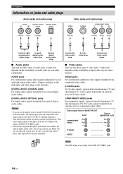
AUDIO jacks For conventional analog audio signals transmitted via optical digital audio cables. DIGITAL AUDIO OPTICAL jacks For digital audio signals transmitted via left jacks. Video signal flow for MONITOR OUT Input Output (MONITOR OUT) PR PR COMPONENT VIDEO PB PB Y Y S VIDEO VIDEO Note The OSD signal is not output at the analog AUDIO OUT (REC) jacks. • Pull out the cap from dust. ■ Video jacks This unit has three types of video jacks. Connection depends on the availability of audio jacks on your other components. Connection depends on the availability of ...
AUDIO jacks For conventional analog audio signals transmitted via optical digital audio cables. DIGITAL AUDIO OPTICAL jacks For digital audio signals transmitted via left jacks. Video signal flow for MONITOR OUT Input Output (MONITOR OUT) PR PR COMPONENT VIDEO PB PB Y Y S VIDEO VIDEO Note The OSD signal is not output at the analog AUDIO OUT (REC) jacks. • Pull out the cap from dust. ■ Video jacks This unit has three types of video jacks. Connection depends on the availability of audio jacks on your other components. Connection depends on the availability of ...

Owner's Manual
Page 19
English 15 En make an analog or digital connection besides the HDMI connection (see page 16). - You can play back pictures by connecting your video monitor and video source component to this unit, - To enjoy the sound from the connected video monitor. PREPARATION Information on HDMI™ Connections Audio signals input at the HDMI jack are output to the connected video monitor only when this unit is turned on and set to the input source (DVD or DTV/CBL). mute the volume of each connected component. ■ HDMI jack and cable plug HDMI HDMI cable plug y • We ...
English 15 En make an analog or digital connection besides the HDMI connection (see page 16). - You can play back pictures by connecting your video monitor and video source component to this unit, - To enjoy the sound from the connected video monitor. PREPARATION Information on HDMI™ Connections Audio signals input at the HDMI jack are output to the connected video monitor only when this unit is turned on and set to the input source (DVD or DTV/CBL). mute the volume of each connected component. ■ HDMI jack and cable plug HDMI HDMI cable plug y • We ...
Owner's Manual
Page 20
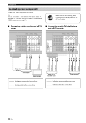
Connections Connecting video components Connect the video components as follows. y You can also connect a video monitor, DVD player, digital TV, and cable TV to this unit and other components are unplugged from the AC wall outlets. ■ Connecting a video monitor and a DVD player ■ Connecting a cable TV/satellite tuner and a DVD recorder COMPONENT VIDEO DVD DTV/CBL DVR MONITOR OUT OUT DVD DVD DTV/CBL VIDEO DTV/CBL IN DVR OUT HDMI MONITOR OUT PR DIGITAL INPUT PB S VIDEO OPTICAL CD 3 Y DTV/ CBL 2 MULTI CH INPUT FRONT SURROUND CENTER L VIDEO DVD DTV/CBL L AUDIO...
Connections Connecting video components Connect the video components as follows. y You can also connect a video monitor, DVD player, digital TV, and cable TV to this unit and other components are unplugged from the AC wall outlets. ■ Connecting a video monitor and a DVD player ■ Connecting a cable TV/satellite tuner and a DVD recorder COMPONENT VIDEO DVD DTV/CBL DVR MONITOR OUT OUT DVD DVD DTV/CBL VIDEO DTV/CBL IN DVR OUT HDMI MONITOR OUT PR DIGITAL INPUT PB S VIDEO OPTICAL CD 3 Y DTV/ CBL 2 MULTI CH INPUT FRONT SURROUND CENTER L VIDEO DVD DTV/CBL L AUDIO...