
Owner's Manual
Page 3
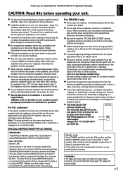
...9679; Do not use this manual carefully. Never pull the wires themselves. ● Be sure to the HIGH or LOW position, this YAMAHA NS-P210 Speaker Package. Never allow a space of this apparatus may be damaged. ● When using an amplifier with this appliance, it in a ...from warping or discoloring, do not position with the letter N or coloured BLACK. For U.K. YAMAHA shall not be knocked over or struck by improper placement or installation of this speaker system. ● VOLTAGE SELECTOR VOLTAGE SELECTOR (General model only) The VOLTAGE SELECTOR on the...
...9679; Do not use this manual carefully. Never pull the wires themselves. ● Be sure to the HIGH or LOW position, this YAMAHA NS-P210 Speaker Package. Never allow a space of this apparatus may be damaged. ● When using an amplifier with this appliance, it in a ...from warping or discoloring, do not position with the letter N or coloured BLACK. For U.K. YAMAHA shall not be knocked over or struck by improper placement or installation of this speaker system. ● VOLTAGE SELECTOR VOLTAGE SELECTOR (General model only) The VOLTAGE SELECTOR on the...
Owner's Manual
Page 4
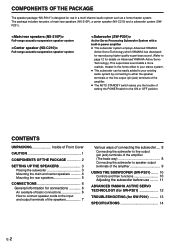
COMPONENTS OF THE PACKAGE The speaker package "NS-P210" is designed for use ......... 11 ADVANCED YAMAHA ACTIVE SERVO TECHNOLOGY (for SW-P201 12 TROUBLESHOOTING (for SW-P201) ......... 13 SPECIFICATIONS 14 E-2 The package includes two pairs... Inside of Front Cover CAUTION 1 COMPONENTS OF THE PACKAGE 2 SETTING UP THE SPEAKERS 3 Placing the subwoofer 3 Mounting the main and center speakers .......... 4 Mounting the rear speakers 5 CONNECTIONS 6 General information for details on Advanced YAMAHA Active Servo Technology.) This super-bass sound adds a more realistic, theater-in power...
COMPONENTS OF THE PACKAGE The speaker package "NS-P210" is designed for use ......... 11 ADVANCED YAMAHA ACTIVE SERVO TECHNOLOGY (for SW-P201 12 TROUBLESHOOTING (for SW-P201) ......... 13 SPECIFICATIONS 14 E-2 The package includes two pairs... Inside of Front Cover CAUTION 1 COMPONENTS OF THE PACKAGE 2 SETTING UP THE SPEAKERS 3 Placing the subwoofer 3 Mounting the main and center speakers .......... 4 Mounting the rear speakers 5 CONNECTIONS 6 General information for details on Advanced YAMAHA Active Servo Technology.) This super-bass sound adds a more realistic, theater-in power...
Owner's Manual
Page 5
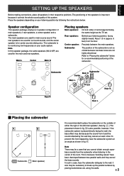
... parallel surfaces by following the instructions below for the main and rear speakers. E-3 The main speakers are not highly directional. About 1.8 m (approx. 6 feet) from the subwoofer when listening in their respective positions. Speaker configuration This speaker package employs a 6 speaker configuration: 2 main speakers, 2 rear speakers, a center speaker and a subwoofer. The subwoofer is for reinforcing low frequencies on your listening...
... parallel surfaces by following the instructions below for the main and rear speakers. E-3 The main speakers are not highly directional. About 1.8 m (approx. 6 feet) from the subwoofer when listening in their respective positions. Speaker configuration This speaker package employs a 6 speaker configuration: 2 main speakers, 2 rear speakers, a center speaker and a subwoofer. The subwoofer is for reinforcing low frequencies on your listening...
Owner's Manual
Page 6
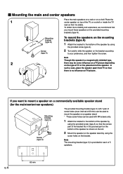
...tighten the screw. To obtain more stability and usefulness, we recommend that you want to mount a speaker on a commercially available speaker stand (for each of the TV, on a shelf or inside the TV rack so that there ...is provided for the main/center/rear speakers) Mounting bracket (type C) Screw (type A) The provided mounting bracket (type C) with 1 pair of ...) can be used with M4 screws only. 1 Attach the bracket to the bottom of the speaker by using the provided screw (type A) so that the convex part of the bracket fits in the grooved...
...tighten the screw. To obtain more stability and usefulness, we recommend that you want to mount a speaker on a commercially available speaker stand (for each of the TV, on a shelf or inside the TV rack so that there ...is provided for the main/center/rear speakers) Mounting bracket (type C) Screw (type A) The provided mounting bracket (type C) with 1 pair of ...) can be used with M4 screws only. 1 Attach the bracket to the bottom of the speaker by using the provided screw (type A) so that the convex part of the bracket fits in the grooved...
Owner's Manual
Page 7
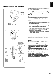
...hang the holes of the mounting bracket on the protruding screws. * Make sure that the screws are securely caught by the narrow parts of the speaker by using the provided mounting brackets (type B) Note It is recommended that no one will injure his/ her head or face with the edge of... the bracket. English Ⅵ Mounting the rear speakers 1 Mounting bracket (type B) Screw (type B) 2 3 Mounting bracket (type B) Wall/ wall support 65 mm Tapping screw (Available at the hardware store) Min. 12 mm Mount ...
...hang the holes of the mounting bracket on the protruding screws. * Make sure that the screws are securely caught by the narrow parts of the speaker by using the provided mounting brackets (type B) Note It is recommended that no one will injure his/ her head or face with the edge of... the bracket. English Ⅵ Mounting the rear speakers 1 Mounting bracket (type B) Screw (type B) 2 3 Mounting bracket (type B) Wall/ wall support 65 mm Tapping screw (Available at the hardware store) Min. 12 mm Mount ...

Owner's Manual
Page 8
... sound will be connected to reverse the polarity (+, -). B REAR L Amplifier Right E-6 Left Main speakers Choose one speaker to the left (marked L) terminals of your amplifier, and another speaker to the right (marked R) terminals. ● The subwoofer can be unnatural and lack bass. *...components after all connections are completed. ● Connect the main, center and rear speakers to the speaker output terminals of the amplifier. (Refer to page 9 for details.) Center speaker Rear speakers Right Left Subwoofer POWER ON OFF REAR R REAR L CENTER VOLUME STANDBY-RED ...
... sound will be connected to reverse the polarity (+, -). B REAR L Amplifier Right E-6 Left Main speakers Choose one speaker to the left (marked L) terminals of your amplifier, and another speaker to the right (marked R) terminals. ● The subwoofer can be unnatural and lack bass. *...components after all connections are completed. ● Connect the main, center and rear speakers to the speaker output terminals of the amplifier. (Refer to page 9 for details.) Center speaker Rear speakers Right Left Subwoofer POWER ON OFF REAR R REAR L CENTER VOLUME STANDBY-RED ...
Owner's Manual
Page 9
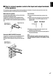
... to the input and output terminals of the cords. Do not bundle or roll up the excess part of the speakers For connections, keep the speaker cords as short as possible. If the connections are faulty, no line. Red: positive (+) Black: negative (-) White broken line How to lock securely on the... cord's wire end. 4 Test the firmness of the connection by pulling lightly on the cord at the terminal. Note Do not let the bare speaker wires touch each other as shown in the figure. 2 Insert the bare wire end properly into the terminal hole. [Remove approx. 10 mm (3/8") insulation ...
... to the input and output terminals of the cords. Do not bundle or roll up the excess part of the speakers For connections, keep the speaker cords as short as possible. If the connections are faulty, no line. Red: positive (+) Black: negative (-) White broken line How to lock securely on the... cord's wire end. 4 Test the firmness of the connection by pulling lightly on the cord at the terminal. Note Do not let the bare speaker wires touch each other as shown in the figure. 2 Insert the bare wire end properly into the terminal hole. [Remove approx. 10 mm (3/8") insulation ...
Owner's Manual
Page 10
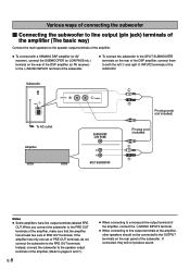
... the subwoofer to line output (pin jack) terminals of the amplifier (The basic way) Connect the main speakers to the speaker output terminals of the amplifier. ● To connect with a YAMAHA DSP amplifier (or AV receiver), connect the SUBWOOFER (or LOW PASS etc.) terminal on the rear of ... terminals. Subwoofer POWER ON OFF VOLUME STANDBY-RED ON-GREEN AUTO STANDBY HIGH LOW OFF 0 I0 INPUT2 /MONO INPUT1 FROM AMPLIFIER OUTPUT TO SPEAKERS INPUT2 To AC outlet Amplifier /MONO SUBWOOFER (LOW PASS) Pin plug cords (not included) Pin plug cord (included) SPLIT SUBWOOFER Notes ●...
... the subwoofer to line output (pin jack) terminals of the amplifier (The basic way) Connect the main speakers to the speaker output terminals of the amplifier. ● To connect with a YAMAHA DSP amplifier (or AV receiver), connect the SUBWOOFER (or LOW PASS etc.) terminal on the rear of ... terminals. Subwoofer POWER ON OFF VOLUME STANDBY-RED ON-GREEN AUTO STANDBY HIGH LOW OFF 0 I0 INPUT2 /MONO INPUT1 FROM AMPLIFIER OUTPUT TO SPEAKERS INPUT2 To AC outlet Amplifier /MONO SUBWOOFER (LOW PASS) Pin plug cords (not included) Pin plug cord (included) SPLIT SUBWOOFER Notes ●...
Owner's Manual
Page 11
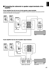
...INPUT2 /MONO INPUT1 FROM AMPLIFIER OUTPUT TO SPEAKERS INPUT1 FROM AMPLIFIER OUTPUT TO SPEAKERS Speaker output terminals To AC outlet Amplifier If your amplifier has only one set of main speaker output terminals Connect the speaker output terminals of the amplifier to the INPUT1...I0 INPUT2 /MONO INPUT1 FROM AMPLIFIER OUTPUT TO SPEAKERS INPUT1 FROM AMPLIFIER OUTPUT TO SPEAKERS To AC outlet A B Amplifier Speaker output terminals (Both A and B speaker outputs must be ON.) E-9 English Ⅵ Connecting the subwoofer to speaker output terminals of the amplifier If your amplifier...
...INPUT2 /MONO INPUT1 FROM AMPLIFIER OUTPUT TO SPEAKERS INPUT1 FROM AMPLIFIER OUTPUT TO SPEAKERS Speaker output terminals To AC outlet Amplifier If your amplifier has only one set of main speaker output terminals Connect the speaker output terminals of the amplifier to the INPUT1...I0 INPUT2 /MONO INPUT1 FROM AMPLIFIER OUTPUT TO SPEAKERS INPUT1 FROM AMPLIFIER OUTPUT TO SPEAKERS To AC outlet A B Amplifier Speaker output terminals (Both A and B speaker outputs must be ON.) E-9 English Ⅵ Connecting the subwoofer to speaker output terminals of the amplifier If your amplifier...
Owner's Manual
Page 12
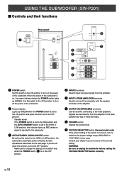
... correct setting. Consult your area. E-10 Set this switch to the OFF position to turn on the power of the amplifier. 6 OUTPUT (TO SPEAKERS) terminals Can be used for connecting to the HIGH or LOW position, the subwoofer's automatic power-switching function operates as described on , the power ...When the power of the subwoofer is in the OFF position. 4 INPUT2 terminals Used to input line level signals from the amplifier to the main speakers by way of these terminals. 7 VOLUME control Adjusts the volume level. 8 VOLTAGE SELECTOR switch (General model only) If the preset setting of the...
... correct setting. Consult your area. E-10 Set this switch to the OFF position to turn on the power of the amplifier. 6 OUTPUT (TO SPEAKERS) terminals Can be used for connecting to the HIGH or LOW position, the subwoofer's automatic power-switching function operates as described on , the power ...When the power of the subwoofer is in the OFF position. 4 INPUT2 terminals Used to input line level signals from the amplifier to the main speakers by way of these terminals. 7 VOLUME control Adjusts the volume level. 8 VOLTAGE SELECTOR switch (General model only) If the preset setting of the...

Owner's Manual
Page 13
...of low frequency input signal differs with a low level of input signal. However, if you change the main speakers NX-210P to adjust the volume balance between the subwoofer and the main speakers by following the procedures described below. Note: It is recommended to set the AUTO STANDBY switch to the ...panel POWER ON 2 OFF POWER ON OFF VOLUME STANDBY-RED ON-GREEN AUTO STANDBY HIGH LOW OFF 0 I0 INPUT2 /MONO INPUT1 FROM AMPLIFIER OUTPUT TO SPEAKERS VOLUME STANDBY-RED ON-GREEN AUTO STANDBY HIGH LOW OFF 0 I0 1, 4 1 Set the VOLUME control to minimum (0). 2 Turn on some sources.
...of low frequency input signal differs with a low level of input signal. However, if you change the main speakers NX-210P to adjust the volume balance between the subwoofer and the main speakers by following the procedures described below. Note: It is recommended to set the AUTO STANDBY switch to the ...panel POWER ON 2 OFF POWER ON OFF VOLUME STANDBY-RED ON-GREEN AUTO STANDBY HIGH LOW OFF 0 I0 INPUT2 /MONO INPUT1 FROM AMPLIFIER OUTPUT TO SPEAKERS VOLUME STANDBY-RED ON-GREEN AUTO STANDBY HIGH LOW OFF 0 I0 1, 4 1 Set the VOLUME control to minimum (0). 2 Turn on some sources.
Owner's Manual
Page 14
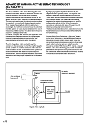
... certain ratio. If the electrical resistance of the voice coil could be the fundamental structure of the speaker unit would become linear with the conventional Yamaha Active Servo Technology, resulting in the correct proportion to accomplish this , a special negative-impedance output-...within the cabinet can provide more natural and dynamic bass reproduction. ADVANCED YAMAHA ACTIVE SERVO TECHNOLOGY (for SW-P201) The theory of low amplitude E-12 Active Servo Processing speakers reproduce the bass frequencies through the employment of frequencies with superior damping characteristics...
... certain ratio. If the electrical resistance of the voice coil could be the fundamental structure of the speaker unit would become linear with the conventional Yamaha Active Servo Technology, resulting in the correct proportion to accomplish this , a special negative-impedance output-...within the cabinet can provide more natural and dynamic bass reproduction. ADVANCED YAMAHA ACTIVE SERVO TECHNOLOGY (for SW-P201) The theory of low amplitude E-12 Active Servo Processing speakers reproduce the bass frequencies through the employment of frequencies with superior damping characteristics...
Owner's Manual
Page 15
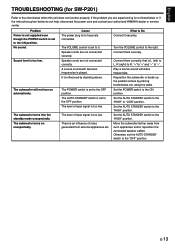
... "+" and "-" to the ON position. Connect them correctly, that is an influence of noise generated from such appliances and/or reposition the connected speaker cables. Connect them securely. Set the POWER switch to "-". Set the AUTO STANDBY switch to the ON position. E-13 Cause The power plug is...not connected correctly. The POWER switch is set to the chart below do not help, disconnect the power cord and contact your authorized YAMAHA dealer or service center. English TROUBLESHOOTING (for SW-P201) Refer to the OFF position. The VOLUME control is set to the ...
... "+" and "-" to the ON position. Connect them correctly, that is an influence of noise generated from such appliances and/or reposition the connected speaker cables. Connect them securely. Set the POWER switch to "-". Set the AUTO STANDBY switch to the ON position. E-13 Cause The power plug is...not connected correctly. The POWER switch is set to the chart below do not help, disconnect the power cord and contact your authorized YAMAHA dealer or service center. English TROUBLESHOOTING (for SW-P201) Refer to the OFF position. The VOLUME control is set to the ...
Owner's Manual
Page 16
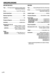
SPECIFICATIONS NX-210P, NX-C210 Type ......... Full-range acoustic-suspension speaker system Magnetically shielded type Driver 8 cm (3-1/8") cone type Nominal Input Power 30W Maximum Input Power 100W Impedance 6Ω Frequency Response 65 Hz-20 kHz Sensitivity 86 dB/2.83V/m Dimensions (W x H x D)
SPECIFICATIONS NX-210P, NX-C210 Type ......... Full-range acoustic-suspension speaker system Magnetically shielded type Driver 8 cm (3-1/8") cone type Nominal Input Power 30W Maximum Input Power 100W Impedance 6Ω Frequency Response 65 Hz-20 kHz Sensitivity 86 dB/2.83V/m Dimensions (W x H x D)


