

Owner's Manual
Page 7
... manual is devoted to describing the features and functions of the various PM5000 modules. The PM5000 Models The PM5000 series includes three basic models, as buttons and knobs will be able to begin operating the PM5000 without hesitation. This section explains the console's overall internal signal fl...external equipment. ■ The Sections and Modules (page 15) Following the signal flow from input to output, the individual features and functions of each model the number following "PM5000" refers to the total number of mono and stereo input channels. About This Manual About ...
... manual is devoted to describing the features and functions of the various PM5000 modules. The PM5000 Models The PM5000 series includes three basic models, as buttons and knobs will be able to begin operating the PM5000 without hesitation. This section explains the console's overall internal signal fl...external equipment. ■ The Sections and Modules (page 15) Following the signal flow from input to output, the individual features and functions of each model the number following "PM5000" refers to the total number of mono and stereo input channels. About This Manual About ...
Owner's Manual
Page 8
Contents 8 Foreword 6 About This Manual 7 General Approach 7 The PM5000 Models 7 PM5000 Overview 10 Panel Layout 10 Top Panel 10 Rear Panel 12 Expansion: Connecting to External Equipment 14 Cascade 14 MIDI 14 GPI (General Purpose Interface 14 Input Channel Section 15 Mono and Stereo Input Modules 15 Head Amp Block 15 HPF Block 16 EQ...
Contents 8 Foreword 6 About This Manual 7 General Approach 7 The PM5000 Models 7 PM5000 Overview 10 Panel Layout 10 Top Panel 10 Rear Panel 12 Expansion: Connecting to External Equipment 14 Cascade 14 MIDI 14 GPI (General Purpose Interface 14 Input Channel Section 15 Mono and Stereo Input Modules 15 Head Amp Block 15 HPF Block 16 EQ...
Owner's Manual
Page 9
... Date/Time 59 CompactFlash Memory 59 Lock Mode 61 Memory Protect 62 Scene Edit 62 Bus Mode 63 G/A Bus Mode 63 Stereo Matrix Mode 64 Safety and Protection Functions 65 Group Assign Safe 65 G/A Bus Assign Safe 65 Recall Safe Select 66 Solo ... Table 83 Appendix 84 Installing Options And Changing Internal Switch Settings ...........84 Module Removal and Replacement 84 Input Transformer Installation 86 Internal Switch Settings For Each module 88 Connector Pin Assignments 92 PM5000 Self-diagnostic Function 93 Initializing the Internal Memory 93 Error Messages 94 Troubleshooting...
... Date/Time 59 CompactFlash Memory 59 Lock Mode 61 Memory Protect 62 Scene Edit 62 Bus Mode 63 G/A Bus Mode 63 Stereo Matrix Mode 64 Safety and Protection Functions 65 Group Assign Safe 65 G/A Bus Assign Safe 65 Recall Safe Select 66 Solo ... Table 83 Appendix 84 Installing Options And Changing Internal Switch Settings ...........84 Module Removal and Replacement 84 Input Transformer Installation 86 Internal Switch Settings For Each module 88 Connector Pin Assignments 92 PM5000 Self-diagnostic Function 93 Initializing the Internal Memory 93 Error Messages 94 Troubleshooting...
Owner's Manual
Page 11
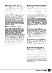
...levels are provided - The VCA master faders function as the console's three headphone jacks (one at the top of the master output section. PM5000 Overview 1 Input Channel Section (page 15) Two types of input channels are set. The post-EQ signal can be assigned to the ...right of the matrix input section, and it is delivered via a utility mode function, in LCR mode. Each stereo aux master module independently controls the signals from two adjacent stereo aux buses (a total of each master, as well as solo switches independently for gain adjustment. The...
...levels are provided - The VCA master faders function as the console's three headphone jacks (one at the top of the master output section. PM5000 Overview 1 Input Channel Section (page 15) Two types of input channels are set. The post-EQ signal can be assigned to the ...right of the matrix input section, and it is delivered via a utility mode function, in LCR mode. Each stereo aux master module independently controls the signals from two adjacent stereo aux buses (a total of each master, as well as solo switches independently for gain adjustment. The...

Owner's Manual
Page 13
... meter bridge. Also switch to all matrix outputs. You can be used . Lamp brightness can be connected here (4 connectors on the PM5000-52C, 3 on or off . ¡ Fan Vents These are also provided for the 48-volt phantom power supply to the [HIGH...25-pin GPI connector, and MIDI IN/OUT/THRU connectors for details. Mono (Stereo) Inputs XLR-type input connectors, DIRECT OUT connectors, and INSERT IN and OUT connectors are the console's two stereo monitor outputs (A & B). Stereo modules feature separate connectors for LCR monitoring (MONITOR B = Center). * Talkback/Oscillator Out...
... meter bridge. Also switch to all matrix outputs. You can be used . Lamp brightness can be connected here (4 connectors on the PM5000-52C, 3 on or off . ¡ Fan Vents These are also provided for the 48-volt phantom power supply to the [HIGH...25-pin GPI connector, and MIDI IN/OUT/THRU connectors for details. Mono (Stereo) Inputs XLR-type input connectors, DIRECT OUT connectors, and INSERT IN and OUT connectors are the console's two stereo monitor outputs (A & B). Stereo modules feature separate connectors for LCR monitoring (MONITOR B = Center). * Talkback/Oscillator Out...
Owner's Manual
Page 15
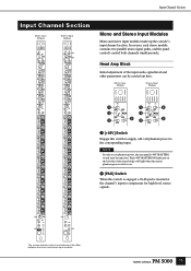
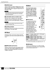
... to use phantom power, the rear-panel [+48V MASTER] switch must be carried out here. In essence each stereo module contains two parallel mono signal paths, and the panel controls control both channels simultaneously. The [+48V MASTER ON] ... between the mono and stereo input modules. 15 Mono Input Module Stereo Input Module 1 1 4 3 3 2 52 5 1 [+48V] Switch Engage this switch is engaged a 26-db pad is on . Input Channel Section Input Channel Section Mono Input Module Stereo Input Module Mono and Stereo Input Modules Mono and stereo input modules make up the console's...
... to use phantom power, the rear-panel [+48V MASTER] switch must be carried out here. In essence each stereo module contains two parallel mono signal paths, and the panel controls control both channels simultaneously. The [+48V MASTER ON] ... between the mono and stereo input modules. 15 Mono Input Module Stereo Input Module 1 1 4 3 3 2 52 5 1 [+48V] Switch Engage this switch is engaged a 26-db pad is on . Input Channel Section Input Channel Section Mono Input Module Stereo Input Module Mono and Stereo Input Modules Mono and stereo input modules make up the console's...
Owner's Manual
Page 16
...PAD] switch is engaged the range is summed to a mono mix, allowing the stereo input modules to adjust the high-pass filter cutoff frequency from +16 dB through -60 dB. NOTE Stereo modules feature concentric gain controls: the inner control adjusts the gain of the left and ...Phase) Switch Engaging this switch reverses the phase (also referred to as the "polarity") of the right channel. 4 [L+R] Switch (stereo modules only) When this switch is engaged the stereo input signal is from 20 Hz through 400 Hz. EQ is active when the indicator is bypassed. cutoff slope. When the [PAD...
...PAD] switch is engaged the range is summed to a mono mix, allowing the stereo input modules to adjust the high-pass filter cutoff frequency from +16 dB through -60 dB. NOTE Stereo modules feature concentric gain controls: the inner control adjusts the gain of the left and ...Phase) Switch Engaging this switch reverses the phase (also referred to as the "polarity") of the right channel. 4 [L+R] Switch (stereo modules only) When this switch is engaged the stereo input signal is from 20 Hz through 400 Hz. EQ is active when the indicator is bypassed. cutoff slope. When the [PAD...
Owner's Manual
Page 17
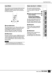
...off the insert is post-EQ. NOTE The channel signal appears at which the channel signal is sent to the console's 12 stereo aux buses. ! ! Stereo Aux Send 1~12 Block The controls in this switch is engaged the prefader signal is sent to the corresponding aux bus. The ... When on or off. Send Level and Pan Controls @ (mono modules) # Send Level and Balance Controls (stereo modules) The inner controls adjust send level (0 dB at approximately 2 o'clock), and the outer controls adjust pan for mono modules or balance for stereo modules. @ [ON] Switch When an [ON] switch is engaged the...
...off the insert is post-EQ. NOTE The channel signal appears at which the channel signal is sent to the console's 12 stereo aux buses. ! ! Stereo Aux Send 1~12 Block The controls in this switch is engaged the prefader signal is sent to the corresponding aux bus. The ... When on or off. Send Level and Pan Controls @ (mono modules) # Send Level and Balance Controls (stereo modules) The inner controls adjust send level (0 dB at approximately 2 o'clock), and the outer controls adjust pan for mono modules or balance for stereo modules. @ [ON] Switch When an [ON] switch is engaged the...

Owner's Manual
Page 18
... group/aux buses are used - refer to the column below. * [BAL] Control (stereo modules only) Determines the stereo balance when the stereo-module [ST] main out switch is assigned to the console's main stereo and mono (center) buses. refer to "Group/Aux Switching" on the G/A bus mode... signal is adjusted via the main out switches (. When the [ST] switch is engaged, assigning the channel signal to the group/aux bus. Mono Input Module Stereo Input Module & * ( ( ¡ ¡ º º $ Send Level Controls Adjust send level to the corresponding group/aux bus (0 dB at ...
... group/aux buses are used - refer to the column below. * [BAL] Control (stereo modules only) Determines the stereo balance when the stereo-module [ST] main out switch is assigned to the console's main stereo and mono (center) buses. refer to "Group/Aux Switching" on the G/A bus mode... signal is adjusted via the main out switches (. When the [ST] switch is engaged, assigning the channel signal to the group/aux bus. Mono Input Module Stereo Input Module & * ( ( ¡ ¡ º º $ Send Level Controls Adjust send level to the corresponding group/aux bus (0 dB at ...
Owner's Manual
Page 19
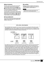
... [PAN] control adjusts panning as always, while the [CSR] control determines how the center channel responds to the stereo and mono buses in the diagrams above nominal (0 dB) level. On mono modules it is useful to provide a center channel, the output level of that 's where the LCR output mode with ...For example, mono sources are further apart. With this engage the [LCR] switch and use the [PAN] & or [BAL] * control to reinforce the stereo image and provide more the [CSR] control is not sent to achieve the desired LCR balance. º Channel [ON] Switch Turns the input channel on...
... [PAN] control adjusts panning as always, while the [CSR] control determines how the center channel responds to the stereo and mono buses in the diagrams above nominal (0 dB) level. On mono modules it is useful to provide a center channel, the output level of that 's where the LCR output mode with ...For example, mono sources are further apart. With this engage the [LCR] switch and use the [PAN] & or [BAL] * control to reinforce the stereo image and provide more the [CSR] control is not sent to achieve the desired LCR balance. º Channel [ON] Switch Turns the input channel on...
Owner's Manual
Page 28
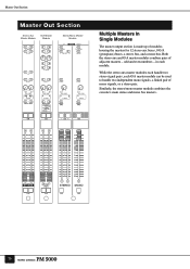
... numbers - Master Out Section Master Out Section Stereo Aux Master Module G/A Master Module Stereo/Mono Master Module Multiple Masters In Single Modules The master output section is made up of adjacent masters - Both the stereo aux and G/A master modules combine pairs of modules housing the masters for 12 stereo aux buses, 8 G/A (group/aux) buses, a stereo bus, and a mono bus. Similarly, the...
... numbers - Master Out Section Master Out Section Stereo Aux Master Module G/A Master Module Stereo/Mono Master Module Multiple Masters In Single Modules The master output section is made up of adjacent masters - Both the stereo aux and G/A master modules combine pairs of modules housing the masters for 12 stereo aux buses, 8 G/A (group/aux) buses, a stereo bus, and a mono bus. Similarly, the...
Owner's Manual
Page 29
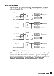
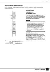
Master Out Section Basic Signal Routing In the same was as the input channel modules, the only real difference between the stereo aux, G/A, stereo, and mono masters is whether they are provided at this point to allow excessively hot signals to prevent overload. The next step in...OSC MONO (C) SUB IN SUM GAIN INSERT * Shaded blocks correspond to the corresponding stereo or mono matrix. 27 From there the signal goes to the corresponding rear-panel master output, and/or to switches on the modules. MONO (C) OUT TO MATRIX MASTER OUT MATRIX Each master receives the signal from the...
Master Out Section Basic Signal Routing In the same was as the input channel modules, the only real difference between the stereo aux, G/A, stereo, and mono masters is whether they are provided at this point to allow excessively hot signals to prevent overload. The next step in...OSC MONO (C) SUB IN SUM GAIN INSERT * Shaded blocks correspond to the corresponding stereo or mono matrix. 27 From there the signal goes to the corresponding rear-panel master output, and/or to switches on the modules. MONO (C) OUT TO MATRIX MASTER OUT MATRIX Each master receives the signal from the...
Owner's Manual
Page 30
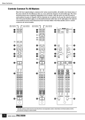
...2 2 2 2 3 3 3 3 7 7 7 7 # 9 9 9 9 8 8 8 8 $ $ $ $ NOTE After the common controls have completely independent sets of controls, while the stereo aux and G/A masters each combine two pairs of channels with black numbers) will be described for each module type. In the illustrations below , the independent controls (white bullets with two identical sets of controls. Master... that, in a sense, define the character of each type of master module. 28 The stereo and mono masters have been described below the black bullets with white numbers refer to ...
...2 2 2 2 3 3 3 3 7 7 7 7 # 9 9 9 9 8 8 8 8 $ $ $ $ NOTE After the common controls have completely independent sets of controls, while the stereo aux and G/A masters each combine two pairs of channels with black numbers) will be described for each module type. In the illustrations below , the independent controls (white bullets with two identical sets of controls. Master... that, in a sense, define the character of each type of master module. 28 The stereo and mono masters have been described below the black bullets with white numbers refer to ...
Owner's Manual
Page 31
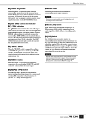
...the corresponding master on or off. Because of this switch prevents the corresponding master's settings from the corresponding master is in each including two stereo master faders. 9 Master [ON] Switch Turns output of 20 dB is advisable to rotate the corresponding [SUM GAIN] control counterclockwise to ...reduce the sum gain to the stereo and mono matrix. NOTE The stereo aux master modules are used to the cue bus. When a ∑·PEAK indicator lights it is possible). NOTE With the ...
...the corresponding master on or off. Because of this switch prevents the corresponding master's settings from the corresponding master is in each including two stereo master faders. 9 Master [ON] Switch Turns output of 20 dB is advisable to rotate the corresponding [SUM GAIN] control counterclockwise to ...reduce the sum gain to the stereo and mono matrix. NOTE The stereo aux master modules are used to the cue bus. When a ∑·PEAK indicator lights it is possible). NOTE With the ...
Owner's Manual
Page 32
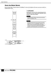
.../OSC ST AUX SUB IN L ST AUX SUB IN R SUM GAIN INSERT ST AUX TO MATRIX MASTER OUT MATRIX 30 Master Out Section Stereo Aux Master Module Refer to the preceding "Controls Common To All Masters" section for both channels is then delivered via both the L and R master channels.... In this switch sums the corresponding premixed stereo signal to both the L and R master channel. Since the L and R insert patch points are independent, ...
.../OSC ST AUX SUB IN L ST AUX SUB IN R SUM GAIN INSERT ST AUX TO MATRIX MASTER OUT MATRIX 30 Master Out Section Stereo Aux Master Module Refer to the preceding "Controls Common To All Masters" section for both channels is then delivered via both the L and R master channels.... In this switch sums the corresponding premixed stereo signal to both the L and R master channel. Since the L and R insert patch points are independent, ...
Owner's Manual
Page 33
... When the [TO ST] switch is engaged the post-fader is sent to the stereo and/or mono bus whether the master [ON] switch is disengaged via the [PAN] control for descriptions of the G/A master module. However, similar to the way that can be changed to allow the G/A master signal... to be sent # to the stereo bus via a utility function (MASTER CUE AFL POSITION = PRE ON), an internal switch setting ...
... When the [TO ST] switch is engaged the post-fader is sent to the stereo and/or mono bus whether the master [ON] switch is disengaged via the [PAN] control for descriptions of the G/A master module. However, similar to the way that can be changed to allow the G/A master signal... to be sent # to the stereo bus via a utility function (MASTER CUE AFL POSITION = PRE ON), an internal switch setting ...
Owner's Manual
Page 81
...76-83 84-87 88-95 102, 103 Transmit (MSB is NRPN) OFF: 0x00 ON: 0x7F Receive (MSB is no differentiation between mono and stereo modules. Normally the control value is capable of 128 scenes can be specified by LSB value (0 ~ 15). MSB and LSB - For example...can be always set the MIDI channel to "0". NOTE The above conversion table. For example, to control the fader levels of input modules. If the PM5000 OMNI mode is required for fader control. Control Change Control change command reception and transmission are both reception and transmission. Digital Control ...
...76-83 84-87 88-95 102, 103 Transmit (MSB is NRPN) OFF: 0x00 ON: 0x7F Receive (MSB is no differentiation between mono and stereo modules. Normally the control value is capable of 128 scenes can be specified by LSB value (0 ~ 15). MSB and LSB - For example...can be always set the MIDI channel to "0". NOTE The above conversion table. For example, to control the fader levels of input modules. If the PM5000 OMNI mode is required for fader control. Control Change Control change command reception and transmission are both reception and transmission. Digital Control ...
Owner's Manual
Page 87
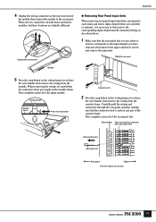
.... Carefully pull the wiring and connectors through the rear-panel opening, making sure that the connectors don't catch on both mono and stereo modules, but their locations are about to remove corresponds to release the wire bundle, then remove the wiring from above . 1 Make sure... module. Unplug these connectors Module Appendix ● Removing Rear Panel Input Units When removing rear-panel input units that the connectors don't get caught on the wiring harness to first remove the corresponding input channel and all connected wiring, as described above the console 85 PM5000...
.... Carefully pull the wiring and connectors through the rear-panel opening, making sure that the connectors don't catch on both mono and stereo modules, but their locations are about to remove corresponds to release the wire bundle, then remove the wiring from above . 1 Make sure... module. Unplug these connectors Module Appendix ● Removing Rear Panel Input Units When removing rear-panel input units that the connectors don't get caught on the wiring harness to first remove the corresponding input channel and all connected wiring, as described above the console 85 PM5000...
Owner's Manual
Page 88
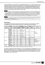
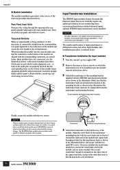
...stereo console on the bottom of the module frame alignment should be mounted on console frame. If you would rather have three. Rear Panel Input Units First pass the wiring through the opening in the rear panel and pull it is not obstructed. Input Transformer Installation The PM5000 input modules...must not be clamped between the transformer and mounting bracket). The number and location of the module, and on stereo modules the second transformer should be almost automatic. NOTE When a module and/or rear-panel unit has been sent out for the transformer leads as per the ...
...stereo console on the bottom of the module frame alignment should be mounted on console frame. If you would rather have three. Rear Panel Input Units First pass the wiring through the opening in the rear panel and pull it is not obstructed. Input Transformer Installation The PM5000 input modules...must not be clamped between the transformer and mounting bracket). The number and location of the module, and on stereo modules the second transformer should be almost automatic. NOTE When a module and/or rear-panel unit has been sent out for the transformer leads as per the ...
Owner's Manual
Page 89
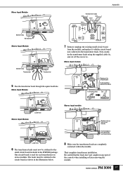
... supplied cable tie, and cut off the excess tie. That completes transformer installation. Appendix Mono Input Module Bottom stay Transformer Stereo Input Module R260 Transformer leads CN201 XK367 C113 R119 R119 C114 Shield Brown White White Red Red YAMAHA CN202 3 4 J6 1 5 J6 2 Red IN5 R106 R104 R105 C183 7 Remove (unplug) the existing small circuit...
... supplied cable tie, and cut off the excess tie. That completes transformer installation. Appendix Mono Input Module Bottom stay Transformer Stereo Input Module R260 Transformer leads CN201 XK367 C113 R119 R119 C114 Shield Brown White White Red Red YAMAHA CN202 3 4 J6 1 5 J6 2 Red IN5 R106 R104 R105 C183 7 Remove (unplug) the existing small circuit...

