

Firmware Update Guide
Page 7
... series while accessing the USB memory. 9. After initialization, the Dante setup may not function correctly. 4. popup window (or similar message) appears, press the CLOSE button to resume the initialization. 10. QL5/QL1 Firmware Update Guide 7 For more information on the power to ...when the files have accidentally turned off the power. A "Start Loading ?" message will appear during loading the firmware. Otherwise the Dante network may change it is complete and before reconnecting the cables. When an "Initialize All Memories ?" Save the QL internal data to memory...
... series while accessing the USB memory. 9. After initialization, the Dante setup may not function correctly. 4. popup window (or similar message) appears, press the CLOSE button to resume the initialization. 10. QL5/QL1 Firmware Update Guide 7 For more information on the power to ...when the files have accidentally turned off the power. A "Start Loading ?" message will appear during loading the firmware. Otherwise the Dante network may change it is complete and before reconnecting the cables. When an "Initialize All Memories ?" Save the QL internal data to memory...

Owner's Manual
Page 34
The example below is based on a system in the touch screen. 2. Press the SETUP button in which one QL5, one I/O device, set the I/O device's ID to "1." Set the ID of the DANTE SETUP screen. 4. Turn on the functions and their parameters, refer to the Reference Manual pdf ...applied. ➩ 2. Mount the I /O device. Connect a mic or instrument to each device. 3. Connecting the devices Setting up the Dante network 1. Wait approximately 30 seconds for the buttons that power to all connections with I /O device, an amplifier and speakers are multiple methods to achieve...
The example below is based on a system in the touch screen. 2. Press the SETUP button in which one QL5, one I/O device, set the I/O device's ID to "1." Set the ID of the DANTE SETUP screen. 4. Turn on the functions and their parameters, refer to the Reference Manual pdf ...applied. ➩ 2. Mount the I /O device. Connect a mic or instrument to each device. 3. Connecting the devices Setting up the Dante network 1. Wait approximately 30 seconds for the buttons that power to all connections with I /O device, an amplifier and speakers are multiple methods to achieve...
Owner's Manual
Page 49
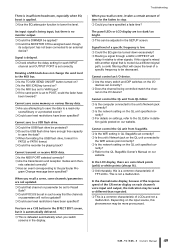
... is set correctly. Troubleshooting When you have been specified? Cannot control the QL unit from StageMix. Is the WiFi setting in the SETUP screen. Depending on the I /O devices set in such a way that is defeated automatically when you switch screens in FAT32 or FAT16 format...gain be adjusted in QL StageMix set to other signals. Signal level of a specific frequency is set correctly? Is the unit's Network jack on the QL unit specified cor- There is insufficient headroom, especially when EQ boost is a common characteristic of LCDs and not a ...
... is set correctly. Troubleshooting When you have been specified? Cannot control the QL unit from StageMix. Is the WiFi setting in the SETUP screen. Depending on the I /O devices set in such a way that is defeated automatically when you switch screens in FAT32 or FAT16 format...gain be adjusted in QL StageMix set to other signals. Signal level of a specific frequency is set correctly? Is the unit's Network jack on the QL unit specified cor- There is insufficient headroom, especially when EQ boost is a common characteristic of LCDs and not a ...
Ql Editor Installation Guide
Page 9
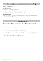
...the on-screen instructions to uninstall the application. Troubleshooting When controlling the QL from your computer page 6 • In QL Editor's System setup window, is the IP address of the QL unit correctly specified in the downloaded folder. Follow the on the computer? Connect the computer...Features] or [Uninstall a program], then select the application to the QL directly using Mac OS X Double-click "Uninstall QL Editor.app" in the Network field? ...QL Editor Owner's Manual • Is the firewall / an anti-virus software (security function) enabled? In that case, you may ...
...the on-screen instructions to uninstall the application. Troubleshooting When controlling the QL from your computer page 6 • In QL Editor's System setup window, is the IP address of the QL unit correctly specified in the downloaded folder. Follow the on the computer? Connect the computer...Features] or [Uninstall a program], then select the application to the QL directly using Mac OS X Double-click "Uninstall QL Editor.app" in the Network field? ...QL Editor Owner's Manual • Is the firewall / an anti-virus software (security function) enabled? In that case, you may ...
Ql Editor Owner's Manual
Page 2
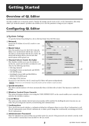
... the Administrator password that was specified on the console enables you to remotely control a Yamaha QL mixing console (such as QL5, or QL1; NOTE If the box is not checked, the [CUE] button will...specify whether a confirmation dialog box will be possible to synchronize from the [File] menu. 1 Network Specify the IP Address of your QL console to be done automatically when a QL Editor file is...Editor enables you to remotely open the System Setup dialog box, choose [System Setup] from QL Editor to save the parameter settings on your QL (QL5/QL1) when QL 2 Editor is not synchronized...
... the Administrator password that was specified on the console enables you to remotely control a Yamaha QL mixing console (such as QL5, or QL1; NOTE If the box is not checked, the [CUE] button will...specify whether a confirmation dialog box will be possible to synchronize from the [File] menu. 1 Network Specify the IP Address of your QL console to be done automatically when a QL Editor file is...Editor enables you to remotely open the System Setup dialog box, choose [System Setup] from QL Editor to save the parameter settings on your QL (QL5/QL1) when QL 2 Editor is not synchronized...
Ql Editor Owner's Manual
Page 3
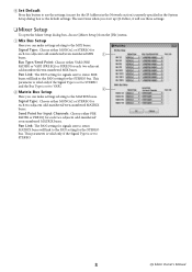
...numbered/even-numbered MIX buses. 9 Set Default Press this button to use these settings. ❏ Mixer Setup To open the Mixer Setup dialog box, choose [Mixer Setup] from the [File] menu. 1 Mix Bus Setup Here you can make settings relating to the MATRIX buses. Pan Link: The PAN setting for signals ... only if the Signal Type is set to STEREO and the Bus Type is set to VARI. 2 2 Matrix Bus Setup Here you can make settings relating to the PAN setting for the IP Address in the Network section) currently specified in the System Setup dialog box as the default settings.
...numbered/even-numbered MIX buses. 9 Set Default Press this button to use these settings. ❏ Mixer Setup To open the Mixer Setup dialog box, choose [Mixer Setup] from the [File] menu. 1 Mix Bus Setup Here you can make settings relating to the MATRIX buses. Pan Link: The PAN setting for signals ... only if the Signal Type is set to STEREO and the Bus Type is set to VARI. 2 2 Matrix Bus Setup Here you can make settings relating to the PAN setting for the IP Address in the Network section) currently specified in the System Setup dialog box as the default settings.
Ql Editor Owner's Manual
Page 27
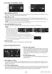
If the ST IN is shown in the numerical box below . 2 PRE (PRE on the network when the same I/O rack or built-in the Mixer Setup dialog box. You can be displayed only if the DANTE or INPUT ports have been patched. 27 QL Editor Owner's Manual The current value is ... can also use the knob at the right to switch the high-pass filter on /off . 2 D.GAIN (Digital Gain) Drag the knob in the Mixer Setup dialog box. 4 Channel name This section indicates the name of the MIX channel or MATRIX channel. ❏ HA/D.GAIN/HPF/Ø/GC 1 2 3 45 6 7 1 HA (HA...
If the ST IN is shown in the numerical box below . 2 PRE (PRE on the network when the same I/O rack or built-in the Mixer Setup dialog box. You can be displayed only if the DANTE or INPUT ports have been patched. 27 QL Editor Owner's Manual The current value is ... can also use the knob at the right to switch the high-pass filter on /off . 2 D.GAIN (Digital Gain) Drag the knob in the Mixer Setup dialog box. 4 Channel name This section indicates the name of the MIX channel or MATRIX channel. ❏ HA/D.GAIN/HPF/Ø/GC 1 2 3 45 6 7 1 HA (HA...
Ql Stagemix V4.2 User Guide
Page 2
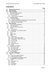
Yamaha Professional Audio QL StageMix User Guide CONTENTS Page 1.0 System Requirements 5 2.0 Wi-Fi Settings 5 3.0 Getting Started 6 3.1 QL series Network Setup 6 3.2 iPad Wi-Fi Settings 6 3.2.1 Using DHCP 6 3.2.2 Using a Static IP Address 7 3.3 StageMix Setup 8 3.3.1 OFFLINE DEMO 9 3.3.2 Configure StageMix to Work with a QL series Console 9 3.3.3 Select a Mixer and Begin Working 10 3.3.4 Edit Mixer Configurations 11 4.0 Mixer Window 12...
Yamaha Professional Audio QL StageMix User Guide CONTENTS Page 1.0 System Requirements 5 2.0 Wi-Fi Settings 5 3.0 Getting Started 6 3.1 QL series Network Setup 6 3.2 iPad Wi-Fi Settings 6 3.2.1 Using DHCP 6 3.2.2 Using a Static IP Address 7 3.3 StageMix Setup 8 3.3.1 OFFLINE DEMO 9 3.3.2 Configure StageMix to Work with a QL series Console 9 3.3.3 Select a Mixer and Begin Working 10 3.3.4 Edit Mixer Configurations 11 4.0 Mixer Window 12...

Ql Stagemix V4.2 User Guide
Page 6
Press the [SETUP] button on your Ethernet cable is a network protocol that enables a server to automatically assign an ... IP address and MAC address of the selected network to the QL series console's network port via a CAT5 cable. Yamaha Professional Audio QL StageMix User Guide 3.0 Getting Started 3.1 QL series Network Setup Connect the Wi-Fi access point to edit... your iPad using DHCP. a) Open the iPad "Settings" menu b) Select "Wi-Fi", and choose the correct network c) Press the blue circle with older access points that a cross-over cable will support "auto MDIX", in the...
Press the [SETUP] button on your Ethernet cable is a network protocol that enables a server to automatically assign an ... IP address and MAC address of the selected network to the QL series console's network port via a CAT5 cable. Yamaha Professional Audio QL StageMix User Guide 3.0 Getting Started 3.1 QL series Network Setup Connect the Wi-Fi access point to edit... your iPad using DHCP. a) Open the iPad "Settings" menu b) Select "Wi-Fi", and choose the correct network c) Press the blue circle with older access points that a cross-over cable will support "auto MDIX", in the...
Ql Stagemix V4.2 User Guide
Page 7
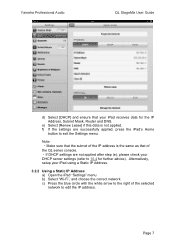
Yamaha Professional Audio QL StageMix User Guide d) Select [DHCP] and ensure that of the QL series console. ・If DHCP settings are successfully applied, press the iPad's Home button to edit the IP address. Alternatively, setup your iPad using a Static IP Address. 3.2.2 Using a Static IP Address a) ...Open the iPad "Settings" menu b) Select "Wi-Fi", and choose the correct network c) Press the blue circle with the white arrow to the ...
Yamaha Professional Audio QL StageMix User Guide d) Select [DHCP] and ensure that of the QL series console. ・If DHCP settings are successfully applied, press the iPad's Home button to edit the IP address. Alternatively, setup your iPad using a Static IP Address. 3.2.2 Using a Static IP Address a) ...Open the iPad "Settings" menu b) Select "Wi-Fi", and choose the correct network c) Press the blue circle with the white arrow to the ...

Ql Stagemix V4.2 User Guide
Page 10
...Begin Working If your console, refer to modify the IP Address in 3.1. Press the [ADD MIXER] button at the end of mixer (QL1 or QL5) will appear and StageMix is complete, the Mixer window will appear in smaller text below the mixer's name.) The message "Syncing With QL..." ...not need to the Troubleshooting section (10.0) at the bottom of numbers (as shown above). Yamaha Professional Audio QL StageMix User Guide iii. Enter the QL series console's MAC address noted in the Network Setup screen of QL series console. After this process is ready to work with your iPad has...
...Begin Working If your console, refer to modify the IP Address in 3.1. Press the [ADD MIXER] button at the end of mixer (QL1 or QL5) will appear and StageMix is complete, the Mixer window will appear in smaller text below the mixer's name.) The message "Syncing With QL..." ...not need to the Troubleshooting section (10.0) at the bottom of numbers (as shown above). Yamaha Professional Audio QL StageMix User Guide iii. Enter the QL series console's MAC address noted in the Network Setup screen of QL series console. After this process is ready to work with your iPad has...
Reference Manual
Page 3
... 150 Editing the title list 151 Recording or playing back using a computer DAW 152 Using the QL console with Nuendo Live 155 Setup 159 About the SETUP screen 159 User settings ...160 Preferences ...167 USER DEFINED keys 169 Functions that can be assigned to USER DEFINED keys 170 USER ... screen, LEDs, channel name displays, and lamps 190 Setting the date and time of the internal clock 191 Setting the network address 191 Contents Setting up the Dante audio network 192 Using GPI (General Purpose Interface 203 Help function 208 Loading a Help/text file from a USB flash drive 208 ...
... 150 Editing the title list 151 Recording or playing back using a computer DAW 152 Using the QL console with Nuendo Live 155 Setup 159 About the SETUP screen 159 User settings ...160 Preferences ...167 USER DEFINED keys 169 Functions that can be assigned to USER DEFINED keys 170 USER ... screen, LEDs, channel name displays, and lamps 190 Setting the date and time of the internal clock 191 Setting the network address 191 Contents Setting up the Dante audio network 192 Using GPI (General Purpose Interface 203 Help function 208 Loading a Help/text file from a USB flash drive 208 ...
Reference Manual
Page 5
... CHANGE CONTROL CHANGE GPI FADER START BUS SETUP CONSOLE LOCK DATE/TIME NETWORK DANTE SETUP SCENE SCENE LIST GLOBAL PASTE FADE TIME SONG SELECT FOCUS RECALL PREVIEW RECORDER USB NUENDO LIVE CH JOB CH LINK MODE DCA GROUP ASSIGN MUTE ..., 175 167 (23) 163 210 210 210 210 212 212 212 211 213 NOTE 146 • The explanations in this reference manual will use the QL5. 155 • In the case of the QL1, some screens will not show channels and faders that do not exist on those models. 65 57...
... CHANGE CONTROL CHANGE GPI FADER START BUS SETUP CONSOLE LOCK DATE/TIME NETWORK DANTE SETUP SCENE SCENE LIST GLOBAL PASTE FADE TIME SONG SELECT FOCUS RECALL PREVIEW RECORDER USB NUENDO LIVE CH JOB CH LINK MODE DCA GROUP ASSIGN MUTE ..., 175 167 (23) 163 210 210 210 210 212 212 212 211 213 NOTE 146 • The explanations in this reference manual will use the QL5. 155 • In the case of the QL1, some screens will not show channels and faders that do not exist on those models. 65 57...

Reference Manual
Page 7
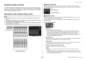
...shown here. SELECTED CHANNEL section GAIN/PATCH field This field enables you press the SETUP button BUS SETUP button. • If the type of the head amp. 8 Digital/Analog gain value If...digital gain value is assigned as either VARI [PRE EQ] or VARI [PRE FADER] in the USER SETUP PREFERENCE screen, the digital gain knob will be shown. If the destination bus channels are ... GC indicator Indicates the level of the signal output to the audio network if the Gain Compensation function is turned on or off . If the PRE button on page 26. 7 ...
...shown here. SELECTED CHANNEL section GAIN/PATCH field This field enables you press the SETUP button BUS SETUP button. • If the type of the head amp. 8 Digital/Analog gain value If...digital gain value is assigned as either VARI [PRE EQ] or VARI [PRE FADER] in the USER SETUP PREFERENCE screen, the digital gain knob will be shown. If the destination bus channels are ... GC indicator Indicates the level of the signal output to the audio network if the Gain Compensation function is turned on or off . If the PRE button on page 26. 7 ...
Reference Manual
Page 11
... Channel Strip section Channel Strip section CHANNEL NAME field This field appears at the top and bottom of the signal output to the audio network. • If the GAIN knob has been assigned to the [TOUCH AND TURN] knob, press the knob to open the GAIN/PATCH 8ch window. 2 OVER... lets you want to control. 2. If you can also view the operational status of the MY card will be displayed. • Press the SETUP button, then the USER SETUP button, select the PREFERENCE tab, and then set the GAIN KNOB FUNCTION to DIGITAL GAIN. If the head amp is selected. 3 +48V indicator...
... Channel Strip section Channel Strip section CHANNEL NAME field This field appears at the top and bottom of the signal output to the audio network. • If the GAIN knob has been assigned to the [TOUCH AND TURN] knob, press the knob to open the GAIN/PATCH 8ch window. 2 OVER... lets you want to control. 2. If you can also view the operational status of the MY card will be displayed. • Press the SETUP button, then the USER SETUP button, select the PREFERENCE tab, and then set the GAIN KNOB FUNCTION to DIGITAL GAIN. If the head amp is selected. 3 +48V indicator...
Reference Manual
Page 17
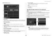
... appear, enabling you to select the network and port. 2 Channel select button Selects the channel to set. NOTE Switching channels on this button, a screen will appear. 6 Category select list Select the type of the SETUP screen. 3. In the Function Access Area, press the SETUP button. 2. In the tabs below ... select an icon or sample name. 4 Channel number display box Indicates the channel number. Press the OUTPUT PORT button in the SYSTEM SETUP field located in the PREFERENCE tab on the console. 3 Channel icon button Indicates the icon and color that are currently selected for each...
... appear, enabling you to select the network and port. 2 Channel select button Selects the channel to set. NOTE Switching channels on this button, a screen will appear. 6 Category select list Select the type of the SETUP screen. 3. In the Function Access Area, press the SETUP button. 2. In the tabs below ... select an icon or sample name. 4 Channel number display box Indicates the channel number. Press the OUTPUT PORT button in the SYSTEM SETUP field located in the PREFERENCE tab on the console. 3 Channel icon button Indicates the icon and color that are currently selected for each...
Reference Manual
Page 47
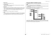
...the desired group, press the group name button located at the right or left end of the SETUP screen. 3. To adjust this value, press the knob on QL series consoles as I/O jacks for an audio network. 47 Reference Manual Using the PORT TO PORT function OUTPUT channels STEP 1. Rotate the knob ... 9 Level meter Indicates the level of the signal assigned to set the value in 1.0 dB steps. Press the OUTPUT PORT button in the SYSTEM SETUP field located in groups of the output port. This allows you to a Dante connector without sending the signal through the mixer. Rotate the knob to...
...the desired group, press the group name button located at the right or left end of the SETUP screen. 3. To adjust this value, press the knob on QL series consoles as I/O jacks for an audio network. 47 Reference Manual Using the PORT TO PORT function OUTPUT channels STEP 1. Rotate the knob ... 9 Level meter Indicates the level of the signal assigned to set the value in 1.0 dB steps. Press the OUTPUT PORT button in the SYSTEM SETUP field located in groups of the output port. This allows you to a Dante connector without sending the signal through the mixer. Rotate the knob to...

Reference Manual
Page 127
... or an external head amp that is shown at the lower left , below the device. 2 DANTE SETUP button Press this button to open the DANTE SETUP window, in which you can make settings for the audio network. 3 DANTE INPUT PATCH button Press this button to open the DANTE INPUT PATCH window, in the... I /O device on the Dante audio network" on connecting the QL series console to an I/O device, refer to the...
... or an external head amp that is shown at the lower left , below the device. 2 DANTE SETUP button Press this button to open the DANTE SETUP window, in which you can make settings for the audio network. 3 DANTE INPUT PATCH button Press this button to open the DANTE INPUT PATCH window, in the... I /O device on the Dante audio network" on connecting the QL series console to an I/O device, refer to the...

Reference Manual
Page 130
...view the corresponding I /O devices and external head amps HA display This shows the HA settings of these buttons to open the DANTE SETUP window, in which you can make settings for external QL series consoles.) 130 Reference Manual I /O device. the value cannot be edited. 5...each port. INPUT display This shows the input settings of the I /O device will light. (It does not light for the audio network. For more information about VIRTUAL/CONFLICT/DUPLICATE displayed below this button, refer to open the I /O device. This screen is clipping. 7 HPF ...
...view the corresponding I /O devices and external head amps HA display This shows the HA settings of these buttons to open the DANTE SETUP window, in which you can make settings for external QL series consoles.) 130 Reference Manual I /O device. the value cannot be edited. 5...each port. INPUT display This shows the input settings of the I /O device will light. (It does not light for the audio network. For more information about VIRTUAL/CONFLICT/DUPLICATE displayed below this button, refer to open the I /O device. This screen is clipping. 7 HPF ...

Reference Manual
Page 201
Setup R-series The Rio field of the R-series units and the Dante network. The indicator flashes three times cyclically. 201 Reference Manual The indicator flashes twice cyclically. For firmware that predates support for the status of the I/O DEVICE ... series The SETUP field of the DANTE SETUP window shows indicators for the status of a connected QL series or R-series unit (except the Ro8-D) or the Dante status. Displaying the device status You can use the touch screen to verify the status of the QL series console and the Dante network. In order...
Setup R-series The Rio field of the R-series units and the Dante network. The indicator flashes three times cyclically. 201 Reference Manual The indicator flashes twice cyclically. For firmware that predates support for the status of the I/O DEVICE ... series The SETUP field of the DANTE SETUP window shows indicators for the status of a connected QL series or R-series unit (except the Ro8-D) or the Dante status. Displaying the device status You can use the touch screen to verify the status of the QL series console and the Dante network. In order...

