
Owner's Manual
Page 2
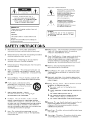
Model: Serial No.: The serial number is operated. 2 Retain Instructions - All the safety and operating instructions should be serviced by qualified service personnel when: A. for a long ...
Model: Serial No.: The serial number is operated. 2 Retain Instructions - All the safety and operating instructions should be serviced by qualified service personnel when: A. for a long ...

Owner's Manual
Page 4
... of digital audio processing to a cozy jazz club. In addition, you about the wonders of a Yamaha Digital Sound Field Processing (DSP) System-an extremely sophisticated audio component. Follow the instructions in channels of amplification on this model mean that no additional amplifiers are the proud owner of digital sound field processing, however...
... of digital audio processing to a cozy jazz club. In addition, you about the wonders of a Yamaha Digital Sound Field Processing (DSP) System-an extremely sophisticated audio component. Follow the instructions in channels of amplification on this model mean that no additional amplifiers are the proud owner of digital sound field processing, however...

Owner's Manual
Page 6
... taken so that the unit is called the standby mode. Use a clean, dry cloth. 10. FREQUENCY STEP switch (China and General Models only) Because the interstation frequency spacing differs in the standby mode. To assure the finest performance, please read the "TROUBLESHOOTING" section regarding... more power than specified is dangerous and may interfere with Canadian ICES-003. Voltages are obstructed, the temperature inside the unit. 4. YAMAHA will rise rapidly. When moving the unit, first disconnect the power plug and the wires connected to clean the unit with a higher...
... taken so that the unit is called the standby mode. Use a clean, dry cloth. 10. FREQUENCY STEP switch (China and General Models only) Because the interstation frequency spacing differs in the standby mode. To assure the finest performance, please read the "TROUBLESHOOTING" section regarding... more power than specified is dangerous and may interfere with Canadian ICES-003. Voltages are obstructed, the temperature inside the unit. 4. YAMAHA will rise rapidly. When moving the unit, first disconnect the power plug and the wires connected to clean the unit with a higher...

Owner's Manual
Page 11
and Canada models only) Batteries (size AA, R6, UM-3) 7 DEC. 0 MOVIE THEATER 1 TUNER 2 TV SPORTS TV/DBS 5 JAZZ CLUB V-AUX 8 +10 ENTER MOVIE THEATER 2 TAPE/MD 3 DISCO VCR 6 ...
and Canada models only) Batteries (size AA, R6, UM-3) 7 DEC. 0 MOVIE THEATER 1 TUNER 2 TV SPORTS TV/DBS 5 JAZZ CLUB V-AUX 8 +10 ENTER MOVIE THEATER 2 TAPE/MD 3 DISCO VCR 6 ...
Owner's Manual
Page 16
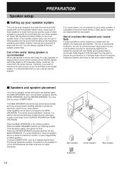
...system will require two speaker pairs: the MAIN SPEAKERS (your normal stereo speakers) and the REAR SPEAKERS, plus one pair of a Yamaha Active Servo Processing Subwoofer System, which contains center-channel signals with Dolby Digital or DTS decoded, dialog, vocals etc. Place the ... shielded speaker.) If using a SUBWOOFER. You may also be using a SUBWOOFER, such as a Yamaha Active Servo Processing Subwoofer System, the position of your audio system. They should be high performance models and have to be nearly 1.8m above or below the television monitor, or use a fivespeaker setup...
...system will require two speaker pairs: the MAIN SPEAKERS (your normal stereo speakers) and the REAR SPEAKERS, plus one pair of a Yamaha Active Servo Processing Subwoofer System, which contains center-channel signals with Dolby Digital or DTS decoded, dialog, vocals etc. Place the ... shielded speaker.) If using a SUBWOOFER. You may also be using a SUBWOOFER, such as a Yamaha Active Servo Processing Subwoofer System, the position of your audio system. They should be high performance models and have to be nearly 1.8m above or below the television monitor, or use a fivespeaker setup...
Owner's Manual
Page 18
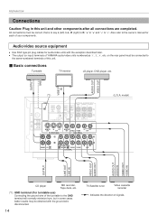
... in this unit. Ⅵ Basic connections Turntable TV monitor LD player, DVD player, etc. Also refer to the same-numbered terminals of YAMAHA audio/video units numbered as 1, 3, 4, etc. model) OUTPUT LINE OUT LINE IN VIDEO OUT AUDIO OUT AUDIO OUT AUDIO IN VIDEO OUT VIDEO IN CD player MD recorder, Tape...
... in this unit. Ⅵ Basic connections Turntable TV monitor LD player, DVD player, etc. Also refer to the same-numbered terminals of YAMAHA audio/video units numbered as 1, 3, 4, etc. model) OUTPUT LINE OUT LINE IN VIDEO OUT AUDIO OUT AUDIO OUT AUDIO IN VIDEO OUT VIDEO IN CD player MD recorder, Tape...
Owner's Manual
Page 19
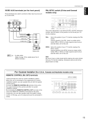
... front panel) These terminals are used to page 18 for details about the S VIDEO terminal.) PREPARATION PAL/NTSC switch (China and General models only) GND Ω UNBAL. NTSC: Set to 6 components can also operate it with the system remote control. When this position if...TV monitor employs, otherwise a picture will not be connected in series. (U.S.A. Set this unit. For Custom Installer (For U.S.A., Canada and Australia models only) REMOTE CONTROL (IN, OUT) terminals These terminals are used for custom installation system, you can be played back normally. Outputs signals ...
... front panel) These terminals are used to page 18 for details about the S VIDEO terminal.) PREPARATION PAL/NTSC switch (China and General models only) GND Ω UNBAL. NTSC: Set to 6 components can also operate it with the system remote control. When this position if...TV monitor employs, otherwise a picture will not be connected in series. (U.S.A. Set this unit. For Custom Installer (For U.S.A., Canada and Australia models only) REMOTE CONTROL (IN, OUT) terminals These terminals are used for custom installation system, you can be played back normally. Outputs signals ...
Owner's Manual
Page 20
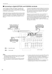
... optical fiber cable that conforms to a digital signal input terminal of input signals between this unit and an external unit, remove the cover from dust. model) Notes q When you must not be connected to this unit. In addition, digital audio signal connections are applicable to both terminals of 32 kHz, 44...
... optical fiber cable that conforms to a digital signal input terminal of input signals between this unit and an external unit, remove the cover from dust. model) Notes q When you must not be connected to this unit. In addition, digital audio signal connections are applicable to both terminals of 32 kHz, 44...
Owner's Manual
Page 21
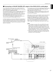
... combi- RF demodulator COAXIAL DIGITAL OUT DOLBY DIGITAL RF IN DVD/LD/CD combi- RF OUT ANALOG OUT OPTICAL DIGITAL OUT (U.S.A. This connection is the Yamaha model APD-1, you must also connect the optical digital signal output terminal of the DVD/LD/CD combi-player to the COAXIAL terminal take priority. This... digital signal input terminals of this case, switch off the power of an LD source encoded with Dolby Digital without interference. Refer to this unit. model) 75Ω UNBAL.
... combi- RF demodulator COAXIAL DIGITAL OUT DOLBY DIGITAL RF IN DVD/LD/CD combi- RF OUT ANALOG OUT OPTICAL DIGITAL OUT (U.S.A. This connection is the Yamaha model APD-1, you must also connect the optical digital signal output terminal of the DVD/LD/CD combi-player to the COAXIAL terminal take priority. This... digital signal input terminals of this case, switch off the power of an LD source encoded with Dolby Digital without interference. Refer to this unit. model) 75Ω UNBAL.
Owner's Manual
Page 22
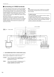
... equipped with an "S" video output can play back or record high quality pictures. S VIDEO terminals transmit video signals separated into luminance (Y) signals and color (C) signals. model) 75Ω UNBAL. VIDEO: The on-screen information is displayed on the front of this unit's VIDEO SIGNAL MONITOR OUT terminal to the "composite" video...
... equipped with an "S" video output can play back or record high quality pictures. S VIDEO terminals transmit video signals separated into luminance (Y) signals and color (C) signals. model) 75Ω UNBAL. VIDEO: The on-screen information is displayed on the front of this unit's VIDEO SIGNAL MONITOR OUT terminal to the "composite" video...
Owner's Manual
Page 23
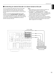
... decoder of this unit. q The settings of "5. LFE/BASS OUT" in the SET MENU mode have no effect on the signals input to these terminals. model) 75Ω UNBAL. MAIN LEVEL" is equipped with additional 6-channel audio signal input terminals (for left main, right main, center, left rear surround, right rear...
... decoder of this unit. q The settings of "5. LFE/BASS OUT" in the SET MENU mode have no effect on the signals input to these terminals. model) 75Ω UNBAL. MAIN LEVEL" is equipped with additional 6-channel audio signal input terminals (for left main, right main, center, left rear surround, right rear...
Owner's Manual
Page 24
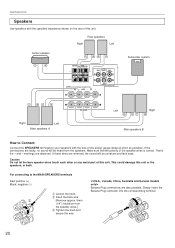
Simply insert the Banana Plug connector into the corresponding terminal. 20 For connecting to your speakers with the specified impedance shown on the rear of this unit or the speakers, or both. Make sure that the polarity of the speaker wires is the + and - Banana Plug connections are reversed, the sound will be unnatural and lack bass. PREPARATION Speakers Use speakers with the wire of the proper gauge (keep as short as possible). If these wires are also possible. This could damage this unit. If the connections are observed. markings are faulty, no sound will ...
Simply insert the Banana Plug connector into the corresponding terminal. 20 For connecting to your speakers with the specified impedance shown on the rear of this unit or the speakers, or both. Make sure that the polarity of the speaker wires is the + and - Banana Plug connections are reversed, the sound will be unnatural and lack bass. PREPARATION Speakers Use speakers with the wire of the proper gauge (keep as short as possible). If these wires are also possible. This could damage this unit. If the connections are observed. markings are faulty, no sound will ...
Owner's Manual
Page 25
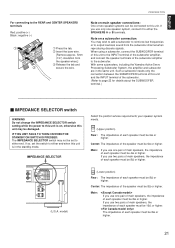
...THIS UNIT FAILS TO TURN ON WHEN THE STANDBY/ON SWITCH IS PRESSED: The IMPEDANCE SELECTOR switch may be 8Ω or higher. model) Select the position whose requirements your speaker system meets. (Upper position) Rear: The impedance of each speaker must be 4Ω ...Insert the bare wire. [Remove approx. 5mm (1/4") insulation from the subwoofer channel when reproducing discrete signals. With some subwoofers, including the Yamaha Active Servo Processing Subwoofer System, the amplifier and subwoofer are in the standby mode. Such a subwoofer needs only the connection between the ...
...THIS UNIT FAILS TO TURN ON WHEN THE STANDBY/ON SWITCH IS PRESSED: The IMPEDANCE SELECTOR switch may be 8Ω or higher. model) Select the position whose requirements your speaker system meets. (Upper position) Rear: The impedance of each speaker must be 4Ω ...Insert the bare wire. [Remove approx. 5mm (1/4") insulation from the subwoofer channel when reproducing discrete signals. With some subwoofers, including the Yamaha Active Servo Processing Subwoofer System, the amplifier and subwoofer are in the standby mode. Such a subwoofer needs only the connection between the ...
Owner's Manual
Page 27
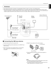
... will probably provide sufficient signal strength. Connect the AM loop antenna lead wires to confirm a good connection. 1 3 2 4. The antenna may result in the following figure. model) AM loop antenna (included) 75-ohm/300-ohm antenna adapter 75-ohm coaxial cable GND 75Ω UNBAL. Return the tab back to the original...
... will probably provide sufficient signal strength. Connect the AM loop antenna lead wires to confirm a good connection. 1 3 2 4. The antenna may result in the following figure. model) AM loop antenna (included) 75-ohm/300-ohm antenna adapter 75-ohm coaxial cable GND 75Ω UNBAL. Return the tab back to the original...
Owner's Manual
Page 29
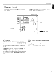
...not to this unit. TOTAL VOLTAGE SELECTOR (*2) To AC outlet (*1): AC OUTLET(S) (U.S.A., Canada, China, Singapore and General models 2 SWITCHED OUTLETS (Australia model 1 SWITCHED OUTLET Use these to connect the power cords of this unit must be used for your components to be set ...AC power cord from the AC outlet if this unit is 100W. (*2): Voltage Selector (China and General Models only) The voltage selector on . OUTPUT MAIN CENTER REAR (SURROUND) SUB WOOFER (*1) (General model) IMPEDANCE SELECTOR SET BEFORE POWER ON REAR : 6ΩMIN. /SPEAKER CENTER : 6ΩMIN. ...
...not to this unit. TOTAL VOLTAGE SELECTOR (*2) To AC outlet (*1): AC OUTLET(S) (U.S.A., Canada, China, Singapore and General models 2 SWITCHED OUTLETS (Australia model 1 SWITCHED OUTLET Use these to connect the power cords of this unit must be used for your components to be set ...AC power cord from the AC outlet if this unit is 100W. (*2): Voltage Selector (China and General Models only) The voltage selector on . OUTPUT MAIN CENTER REAR (SURROUND) SUB WOOFER (*1) (General model) IMPEDANCE SELECTOR SET BEFORE POWER ON REAR : 6ΩMIN. /SPEAKER CENTER : 6ΩMIN. ...
Owner's Manual
Page 65
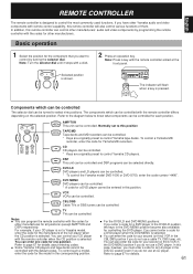
...selector dial. You can be turned to page 67 for details about entering codes. ● Some Yamaha CD players and tape decks cannot be controlled with the remote controller aimed at the front panel....will flash when a key is shown. CD CD CD players can be controlled. * To control the Yamaha model DVD-1000 or DVD-S700, enter the code number "4490". TV TV TVs can be controlled for ..., the keys in the DVD MENU position become also available for your CD player is not a Yamaha model, enter the code for an LD player in the CBL/DBS position if you have other manufacturers....
...selector dial. You can be turned to page 67 for details about entering codes. ● Some Yamaha CD players and tape decks cannot be controlled with the remote controller aimed at the front panel....will flash when a key is shown. CD CD CD players can be controlled. * To control the Yamaha model DVD-1000 or DVD-S700, enter the code number "4490". TV TV TVs can be controlled for ..., the keys in the DVD MENU position become also available for your CD player is not a Yamaha model, enter the code for an LD player in the CBL/DBS position if you have other manufacturers....
Owner's Manual
Page 71
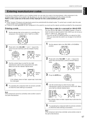
To control such a model, enter the code for the model in the corresponding position. ● If there is no code applicable for your component in the code ...to the CBL/DBS or DVD MENU position. REMOTE CONTROLLER English Entering manufacturer codes If you have a component which is not a Yamaha model, you can control the component with the remote controller. By doing so, you can enter the code for the manufacturer of .../DTS SURROUND CD MOVIE THEATER 1 MOVIE THEATER 2 TAPE/MD 2 Press both of the selector dial. Notes ● Some Yamaha CD players and tape decks cannot be used.
To control such a model, enter the code for the model in the corresponding position. ● If there is no code applicable for your component in the code ...to the CBL/DBS or DVD MENU position. REMOTE CONTROLLER English Entering manufacturer codes If you have a component which is not a Yamaha model, you can control the component with the remote controller. By doing so, you can enter the code for the manufacturer of .../DTS SURROUND CD MOVIE THEATER 1 MOVIE THEATER 2 TAPE/MD 2 Press both of the selector dial. Notes ● Some Yamaha CD players and tape decks cannot be used.
Owner's Manual
Page 72
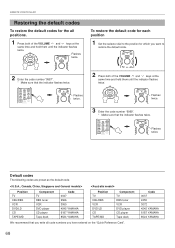
... CBL/DBS VCR DVD/LD CD TAPE/MD Component TV DBS tuner VCR DVD player CD player Tape deck Code 0047 2566 3060 4545 YAMAHA 6187 YAMAHA 8524 YAMAHA Position TV CBL/DBS VCR DVD/LD CD TAPE/MD Component TV DBS tuner VCR DVD player CD player Tape deck We recommend that... "9999". * Make sure that the indicator flashes twice. /DTS SURROUND CD 1 MONO MOVIE DVD/LD 4 ROCK PHONO 7 HALL EXT. Code 0037 2455 3072 4545 YAMAHA 6187 YAMAHA 8524 YAMAHA 68 REMOTE CONTROLLER Restoring the default codes To restore the default codes for which you want to restore the default code. TV Flashes CODE...
... CBL/DBS VCR DVD/LD CD TAPE/MD Component TV DBS tuner VCR DVD player CD player Tape deck Code 0047 2566 3060 4545 YAMAHA 6187 YAMAHA 8524 YAMAHA Position TV CBL/DBS VCR DVD/LD CD TAPE/MD Component TV DBS tuner VCR DVD player CD player Tape deck We recommend that... "9999". * Make sure that the indicator flashes twice. /DTS SURROUND CD 1 MONO MOVIE DVD/LD 4 ROCK PHONO 7 HALL EXT. Code 0037 2455 3072 4545 YAMAHA 6187 YAMAHA 8524 YAMAHA 68 REMOTE CONTROLLER Restoring the default codes To restore the default codes for which you want to restore the default code. TV Flashes CODE...
Owner's Manual
Page 75
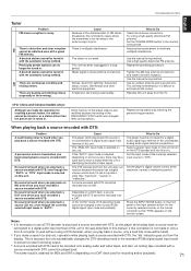
A desired station cannot be tuned in. Previously preset stations can no longer be tuned in this manual. There are continuous crackling and hissing noises. Cause Because of the characteristics of the currently selected input source to a digital audio signal input terminal of this unit in the way described in with DTS cannot be played back. Weak signal or loose antenna connections. A television set at the maximum, neutral or ineffective position. Use the manual tuning method. Although you have recorded a source encoded with DTS. No sound is heard when you play back a ...
A desired station cannot be tuned in. Previously preset stations can no longer be tuned in this manual. There are continuous crackling and hissing noises. Cause Because of the characteristics of the currently selected input source to a digital audio signal input terminal of this unit in the way described in with DTS cannot be played back. Weak signal or loose antenna connections. A television set at the maximum, neutral or ineffective position. Use the manual tuning method. Although you have recorded a source encoded with DTS. No sound is heard when you play back a ...
Owner's Manual
Page 76
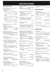
... (by IHF Dynamic Headroom Measuring Method) MAIN L/R (8 ohms/6 ohms/4 ohms/2 ohms) (When both channels are driven) ..... 130W IEC Power [Europe, U.K. and Singapore models only] MAIN L/R (1 kHz, 0.7% THD, 4 ohms) (When both channels are driven) MAIN L/R 10 Hz to 50 kHz Damping Factor (SPEAKER A) MAIN L/R (...1.5 Vp-p or more Signal-to 10 MHz, -3 dB FM SECTION Tuning Range [U.S.A. SUBWOOFER (L.P.F fc = 90 Hz, 18 dB/oct. and Canada models only] MAIN L/R (8 ohms 1.31 dB DIN Standard Output Power Per Channel [Europe, U.K. SPECIFICATIONS AUDIO SECTION Minimum RMS Output Power Per Channel (Power ...
... (by IHF Dynamic Headroom Measuring Method) MAIN L/R (8 ohms/6 ohms/4 ohms/2 ohms) (When both channels are driven) ..... 130W IEC Power [Europe, U.K. and Singapore models only] MAIN L/R (1 kHz, 0.7% THD, 4 ohms) (When both channels are driven) MAIN L/R 10 Hz to 50 kHz Damping Factor (SPEAKER A) MAIN L/R (...1.5 Vp-p or more Signal-to 10 MHz, -3 dB FM SECTION Tuning Range [U.S.A. SUBWOOFER (L.P.F fc = 90 Hz, 18 dB/oct. and Canada models only] MAIN L/R (8 ohms 1.31 dB DIN Standard Output Power Per Channel [Europe, U.K. SPECIFICATIONS AUDIO SECTION Minimum RMS Output Power Per Channel (Power ...


