
Owner's Manual
Page 1
... Operations 17 Preset Tuning 18 Using Digital Sound Field Processor (DSP 21 Setting the SLEEP Timer ....... 26 Remote Control Transmitter ... 27 Notes About the Remote Control Transmitter 28 Troubleshooting 29 Specifications 30 IMPORTANT! Retain this YAMAHA stereo receiver. CAUTION RISK OF ELECTRIC SHOCK CAUTION: TO REDUCE THE RISK OF ELECTRIC SHOCK, DO NOT...
... Operations 17 Preset Tuning 18 Using Digital Sound Field Processor (DSP 21 Setting the SLEEP Timer ....... 26 Remote Control Transmitter ... 27 Notes About the Remote Control Transmitter 28 Troubleshooting 29 Specifications 30 IMPORTANT! Retain this YAMAHA stereo receiver. CAUTION RISK OF ELECTRIC SHOCK CAUTION: TO REDUCE THE RISK OF ELECTRIC SHOCK, DO NOT...
Owner's Manual
Page 4
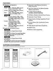
...Remote Control Transmitter R-V701 R-V501 Batteries (size AA, R6, UM-3) Indoor FM Antenna AM Loop Antenna 4 FEATURES q 5 Speaker Configuration R-V701 Front: 80W + 80W (8Ω) RMS Output Power, 0.09% THD, 1 kHz Center: 80W (8Ω) RMS Output Power, 0.1% THD, 1 kHz Rear: 15W + 15W (8Ω) RMS Output Power, 0.7% THD, 1 kHz R-V501...Programs for Digital Sound Field Processing 2 Programs for Dolby Surround Decoding (DOLBY PRO LOGIC and DOLBY PRO LOGIC ENHANCED) R-V501 2 Programs for Digital Sound Field Processing 2 Programs for Dolby Surround Decoding (DOLBY PRO LOGIC and DOLBY 3 STEREO)...
...Remote Control Transmitter R-V701 R-V501 Batteries (size AA, R6, UM-3) Indoor FM Antenna AM Loop Antenna 4 FEATURES q 5 Speaker Configuration R-V701 Front: 80W + 80W (8Ω) RMS Output Power, 0.09% THD, 1 kHz Center: 80W (8Ω) RMS Output Power, 0.1% THD, 1 kHz Rear: 15W + 15W (8Ω) RMS Output Power, 0.7% THD, 1 kHz R-V501...Programs for Digital Sound Field Processing 2 Programs for Dolby Surround Decoding (DOLBY PRO LOGIC and DOLBY PRO LOGIC ENHANCED) R-V501 2 Programs for Digital Sound Field Processing 2 Programs for Dolby Surround Decoding (DOLBY PRO LOGIC and DOLBY 3 STEREO)...

Owner's Manual
Page 9
... watts. Do not let the bare speaker wires touch each other and do not let them touch the metal parts of this unit as possible. R-V501 only For connecting to the REAR and CENTER SPEAKERS terminals Red: positive (+) Black: negative (-) Œ Press the tab. Insert the bare wire.... on . markings are faulty, no sound will supply power to any component whenever this unit is controlled by this unit's POWER switch or the provided remote control transmitter's POWER key. How to Connect: Red: positive (+) Black: negative (-) Ž Œ Œ Press and open the tab. ...
... watts. Do not let the bare speaker wires touch each other and do not let them touch the metal parts of this unit as possible. R-V501 only For connecting to the REAR and CENTER SPEAKERS terminals Red: positive (+) Black: negative (-) Œ Press the tab. Insert the bare wire.... on . markings are faulty, no sound will supply power to any component whenever this unit is controlled by this unit's POWER switch or the provided remote control transmitter's POWER key. How to Connect: Red: positive (+) Black: negative (-) Ž Œ Œ Press and open the tab. ...

Owner's Manual
Page 13
... CENTER LEVEL control. q If you can adjust whole sound level on your audio system by using the VOLUME control (or the VOLUME keys on the remote control transmitter). TEST "TEST" stops flashing and disappears. BALANCE 0 l l 2 2 3 3 4 L5 4 5R 11 Adjust the sound output level of the center speaker to be adjusted...
... CENTER LEVEL control. q If you can adjust whole sound level on your audio system by using the VOLUME control (or the VOLUME keys on the remote control transmitter). TEST "TEST" stops flashing and disappears. BALANCE 0 l l 2 2 3 3 4 L5 4 5R 11 Adjust the sound output level of the center speaker to be adjusted...
Owner's Manual
Page 21
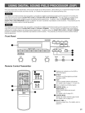
You can create an excellent audio sound field by selecting the suitable program and adding desired adjustments. R-V501 This digital sound field processor has 4 programs; 2 programs for digital sound field processing and 2...- VOLUME + 4 R-V701 PRO LOGIC ENHANCED CNCT VIDEO SUR. MONO MOVIE ROCK HALL R-V501 PRO LOGIC 3 STEREO SUR. Front Panel 1 PRESET STATIONS 2 3 4 5 6 DOWN TUNING UP BASS 0 l l 2 2 3 3 4 5 4 5 TREBLE 0 l l 2 2 3 3 4 5 4 5 Remote Control Transmitter 7 8 TAPE MONITOR TUNER CD PHONO COPY VCR MONITOR LD/TV PROGRAM PROCESSOR ...
You can create an excellent audio sound field by selecting the suitable program and adding desired adjustments. R-V501 This digital sound field processor has 4 programs; 2 programs for digital sound field processing and 2...- VOLUME + 4 R-V701 PRO LOGIC ENHANCED CNCT VIDEO SUR. MONO MOVIE ROCK HALL R-V501 PRO LOGIC 3 STEREO SUR. Front Panel 1 PRESET STATIONS 2 3 4 5 6 DOWN TUNING UP BASS 0 l l 2 2 3 3 4 5 4 5 TREBLE 0 l l 2 2 3 3 4 5 4 5 Remote Control Transmitter 7 8 TAPE MONITOR TUNER CD PHONO COPY VCR MONITOR LD/TV PROGRAM PROCESSOR ...

Owner's Manual
Page 26
.... Lights up. Notes q The SLEEP timer can be canceled by turning off from the display.) Note The SLEEP timer setting can make this unit. R-V701 R-V501 Indicates the SLEEP time. When you can also be controlled only with the POWER switch or disconnecting the power plug of this timer function is... 30 The SLEEP timer is off automatically. To set , and the "SLEEP" indicator is pressed, the SLEEP time will go off the power with the remote control transmitter. NING SLEEP NO ENTER ms AM FM RY ms kHz SLEEP NO Flashes. SETTING THE SLEEP TIMER If you use the SLEEP timer...
.... Lights up. Notes q The SLEEP timer can be canceled by turning off from the display.) Note The SLEEP timer setting can make this unit. R-V701 R-V501 Indicates the SLEEP time. When you can also be controlled only with the POWER switch or disconnecting the power plug of this timer function is... 30 The SLEEP timer is off automatically. To set , and the "SLEEP" indicator is pressed, the SLEEP time will go off the power with the remote control transmitter. NING SLEEP NO ENTER ms AM FM RY ms kHz SLEEP NO Flashes. SETTING THE SLEEP TIMER If you use the SLEEP timer...
Owner's Manual
Page 27
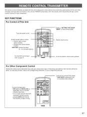
... PAUSE/STOP CD DISC SKIP - A/B/C/D/E: Selects the page (A - VOLUME + Refer to "SETTING THE SLEEP TIMER" on your component's keys. For Other Component Control Identify the remote control transmitter keys with automatic reverse function, pressing DIR A will reverse the direction of the unit. Selects input source. Turns the master volume level up... to a double cassette tape deck. * For a single cassette deck with your component's manual. If the CD player and tape deck connected to this unit are YAMAHA components, then this unit is applicable only to page 21.
... PAUSE/STOP CD DISC SKIP - A/B/C/D/E: Selects the page (A - VOLUME + Refer to "SETTING THE SLEEP TIMER" on your component's keys. For Other Component Control Identify the remote control transmitter keys with automatic reverse function, pressing DIR A will reverse the direction of the unit. Selects input source. Turns the master volume level up... to a double cassette tape deck. * For a single cassette deck with your component's manual. If the CD player and tape deck connected to this unit are YAMAHA components, then this unit is applicable only to page 21.

Owner's Manual
Page 28
... the batteries are correct. (See the illustration inside the battery compartment.) q Remove the batteries if the remote control transmitter will not be no large obstacles between the remote control transmitter and the main unit. q Be sure the polarities are weak. In this case, reposition ...the main unit to work correctly. Replace both batteries with clothing, etc. q If the remote control sensor is directly illuminated by strong lighting (especially an inverter type of fluorescent lamp etc.), it come in contact with new ones. ...
... the batteries are correct. (See the illustration inside the battery compartment.) q Remove the batteries if the remote control transmitter will not be no large obstacles between the remote control transmitter and the main unit. q Be sure the polarities are weak. In this case, reposition ...the main unit to work correctly. Replace both batteries with clothing, etc. q If the remote control sensor is directly illuminated by strong lighting (especially an inverter type of fluorescent lamp etc.), it come in contact with new ones. ...
Owner's Manual
Page 29
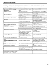
... with Auto tuning. A desired station cannot be tuned in the SYMPTOM column, disconnect the power cord and contact your authorized YAMAHA dealer or service center for best reception. There are connected with a good FM antenna. The sound is degraded when monitoring ... Incorrect output cord connections. Incorrect setting of the main unit. The player should be defective. Relocate this unit. The power to this remote control transmitter are continuous crackling and hissing noises. Only one side speaker outputs the sound. No sound from the rear speakers. A television...
... with Auto tuning. A desired station cannot be tuned in the SYMPTOM column, disconnect the power cord and contact your authorized YAMAHA dealer or service center for best reception. There are connected with a good FM antenna. The sound is degraded when monitoring ... Incorrect output cord connections. Incorrect setting of the main unit. The player should be defective. Relocate this unit. The power to this remote control transmitter are continuous crackling and hissing noises. Only one side speaker outputs the sound. No sound from the rear speakers. A television...

Owner's Manual
Page 30
total Dimensions (W x H x D 435 x 146 x 299 mm (17-1/8" x 5-3/4" x 11-3/4") Weight model 200W [Canada model 240W/290 VA AC Outlet 2 SWITCHED OUTLETS 100W max. model 70W [Canada model 65W Rear 8 ohms, 1 kHz, 0.7% THD 15W Dynamic Power per Channel Front L, R 8 ohms, 1 kHz, 0.09% THD ........80W+80W Center 8 ohms, 1 kHz, 0.1% THD 80W Rear L, R 8 ohms, 1 kHz, 0.7% THD .........15W+15W Front L, R 8 ohms, 1 kHz, 0.09% THD [U.S.A. SPECIFICATIONS AUDIO SECTION Minimum RMS Output Power per Channel (by IHF Dynamic Headroom measuring method) 8/6/4/2 ohms 110/140/190/220W [U.S.A....
total Dimensions (W x H x D 435 x 146 x 299 mm (17-1/8" x 5-3/4" x 11-3/4") Weight model 200W [Canada model 240W/290 VA AC Outlet 2 SWITCHED OUTLETS 100W max. model 70W [Canada model 65W Rear 8 ohms, 1 kHz, 0.7% THD 15W Dynamic Power per Channel Front L, R 8 ohms, 1 kHz, 0.09% THD ........80W+80W Center 8 ohms, 1 kHz, 0.1% THD 80W Rear L, R 8 ohms, 1 kHz, 0.7% THD .........15W+15W Front L, R 8 ohms, 1 kHz, 0.09% THD [U.S.A. SPECIFICATIONS AUDIO SECTION Minimum RMS Output Power per Channel (by IHF Dynamic Headroom measuring method) 8/6/4/2 ohms 110/140/190/220W [U.S.A....


