
Remote Codes
Page 1
... of a ballpoint pen. If it fails, the light blinks six times. How do I program TV remote control codes to the RX-V465/HTR-6240 POWER SOURCE 1 1 5 TRANSMIT CODE SET POWER SLEEP HDMI 2 3 4 AV 2 3 4 AUDIO 6 1 2 V-AUX [ A ] [ B ] DOCK TUNER FM AM PRESET TUNIN G INFO MEMORY MOVIE MUSIC ENHANCER SUR. TRANSMIT The light on the remote...
... of a ballpoint pen. If it fails, the light blinks six times. How do I program TV remote control codes to the RX-V465/HTR-6240 POWER SOURCE 1 1 5 TRANSMIT CODE SET POWER SLEEP HDMI 2 3 4 AV 2 3 4 AUDIO 6 1 2 V-AUX [ A ] [ B ] DOCK TUNER FM AM PRESET TUNIN G INFO MEMORY MOVIE MUSIC ENHANCER SUR. TRANSMIT The light on the remote...

User Guide
Page 1
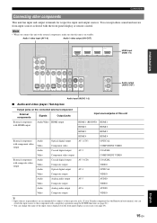
English UABG © 2009 Yamaha Corporation All rights reserved. Example 1: A game console that does not output an audio signal at the HDMI output jack. Continues to this unit AV1 (TV) AV2 AV3 (CD) AV4 AV5 AV6 VIDEO AUX (Front panel) AV5 ...video signal input from the AC wall outlets. ■ HDMI and audio connection Audio output jacks on the connected source component Analog audio output Coaxial digital output Optical digital output Input sources/ jacks of this unit Available HDMI jack AUDIO1 AUDIO HDMI1 AUDIO2 AUDIO HDMI2 AV3 (CD) COAXIAL HDMI3 AV4 OPTICAL HDMI4 ■...
English UABG © 2009 Yamaha Corporation All rights reserved. Example 1: A game console that does not output an audio signal at the HDMI output jack. Continues to this unit AV1 (TV) AV2 AV3 (CD) AV4 AV5 AV6 VIDEO AUX (Front panel) AV5 ...video signal input from the AC wall outlets. ■ HDMI and audio connection Audio output jacks on the connected source component Analog audio output Coaxial digital output Optical digital output Input sources/ jacks of this unit Available HDMI jack AUDIO1 AUDIO HDMI1 AUDIO2 AUDIO HDMI2 AV3 (CD) COAXIAL HDMI3 AV4 OPTICAL HDMI4 ■...

User Guide
Page 2
... BACK/BI-AMP (Example) OPTICAL ( TV ) AV 1 COAXIAL AV 2 COAXIAL (CD) AV 3 OPTICAL AV 4 AV 5 AV 6 AV OUT AUDIO1 AUDIO2 AUDIO OUT SUBWOOFER PRE OUT O OPTICAL AV4 input Audio output HDMI HDMI 4 HDMI4 input HDMI output Set-top box Part 2: Assigning the video input jacks 1 Turn on this unit. 2 Press AV3-4 or AUDIO1-2 on the...
... BACK/BI-AMP (Example) OPTICAL ( TV ) AV 1 COAXIAL AV 2 COAXIAL (CD) AV 3 OPTICAL AV 4 AV 5 AV 6 AV OUT AUDIO1 AUDIO2 AUDIO OUT SUBWOOFER PRE OUT O OPTICAL AV4 input Audio output HDMI HDMI 4 HDMI4 input HDMI output Set-top box Part 2: Assigning the video input jacks 1 Turn on this unit. 2 Press AV3-4 or AUDIO1-2 on the...

Owners Manual
Page 5
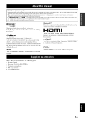
... 11 Information on jacks and cable plugs 13 Connecting a TV monitor or projector 14 Connecting other components 15 Connecting a Yamaha iPod universal dock or Bluetooth™ wireless audio receiver 16 Using the VIDEO AUX jacks on the front panel .... 16 Connecting the FM and AM antennas 17 Connecting... the remote control 44 Setting remote control codes 44 Resetting all remote control codes 44 Advanced setup 45 APPENDIX Troubleshooting 46 General 46 HDMI 49 Tuner (FM/AM 49 Remote control 50 iPod 50 Bluetooth 51 Auto Setup (YPAO 51 Glossary 53 Sound field program information ...
... 11 Information on jacks and cable plugs 13 Connecting a TV monitor or projector 14 Connecting other components 15 Connecting a Yamaha iPod universal dock or Bluetooth™ wireless audio receiver 16 Using the VIDEO AUX jacks on the front panel .... 16 Connecting the FM and AM antennas 17 Connecting... the remote control 44 Setting remote control codes 44 Resetting all remote control codes 44 Advanced setup 45 APPENDIX Troubleshooting 46 General 46 HDMI 49 Tuner (FM/AM 49 Remote control 50 iPod 50 Bluetooth 51 Auto Setup (YPAO 51 Glossary 53 Sound field program information ...

Owners Manual
Page 6
... input x 2 [Video] Component video x 2, composite video x 4 • Audio input (analog) x 2 • Dock input x 1 • V-AUX input [Audio] Analog x 1 [Video] Composite video x 1 Output terminals • Monitor output [Audio/Video] HDMI x 1 [Video] Component video x 1, Composite video x 1 • Audio/Visual output [Audio] Analog x 1 [Video] Composite video x 1 • Audio output Analog x 1 ■ Proprietary Yamaha technology for the creation of sound fields •...
... input x 2 [Video] Component video x 2, composite video x 4 • Audio input (analog) x 2 • Dock input x 1 • V-AUX input [Audio] Analog x 1 [Video] Composite video x 1 Output terminals • Monitor output [Audio/Video] HDMI x 1 [Video] Component video x 1, Composite video x 1 • Audio/Visual output [Audio] Analog x 1 [Video] Composite video x 1 • Audio output Analog x 1 ■ Proprietary Yamaha technology for the creation of sound fields •...
Owners Manual
Page 7
.... Bluetooth™ Bluetooth is a registered trademark and the DTS logos, Symbol, DTS-HD and DTSHD Master Audio are trademarks, or registered trademarks of Yamaha Corporation. "SILENT CINEMA" is a trademark of Bluetooth SIG and is a trademark of the following parts. • Remote control •...8226; y indicates a tip for the information about each position of the parts on the front panel or the remote control. "HDMI," the "HDMI" logo and "High-Definition Multimedia Interface" are trademark of Apple Inc., registered in accordance with a license agreement. Manufactured under ...
.... Bluetooth™ Bluetooth is a registered trademark and the DTS logos, Symbol, DTS-HD and DTSHD Master Audio are trademarks, or registered trademarks of Yamaha Corporation. "SILENT CINEMA" is a trademark of Bluetooth SIG and is a trademark of the following parts. • Remote control •...8226; y indicates a tip for the information about each position of the parts on the front panel or the remote control. "HDMI," the "HDMI" logo and "High-Definition Multimedia Interface" are trademark of Apple Inc., registered in accordance with a license agreement. Manufactured under ...

Owners Manual
Page 8
...the video output cable of speakers (see page 22). Part names and functions Front panel UTD E FG H P STANDBY /ON PHONES SILENT CINEMA HDMI THROUGH INFO MEMORY l PRESET h FM BD/DVD SCENE TV CD AM RADIO l TUNING h TONE CONTROL PROGRAM l h STRAIGHT EFFECT DIRECT INPUT ...OPTIMIZER MIC l h VOLUME VIDEO AUX VIDEO AUDIO PORTABLE A B C JK LM N O I SCENE Switches between standby and on (see page 17). F FM Sets the FM/AM tuner band to ...
...the video output cable of speakers (see page 22). Part names and functions Front panel UTD E FG H P STANDBY /ON PHONES SILENT CINEMA HDMI THROUGH INFO MEMORY l PRESET h FM BD/DVD SCENE TV CD AM RADIO l TUNING h TONE CONTROL PROGRAM l h STRAIGHT EFFECT DIRECT INPUT ...OPTIMIZER MIC l h VOLUME VIDEO AUX VIDEO AUDIO PORTABLE A B C JK LM N O I SCENE Switches between standby and on (see page 17). F FM Sets the FM/AM tuner band to ...
Owners Manual
Page 9
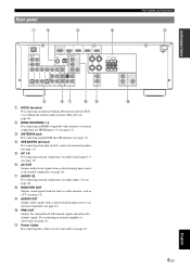
... UNBAL. (BD/DVD) HDMI 1 COMPONENT VIDEO PR HDMI 2 FM GND AM PB Y VIDEO MONITOR OUT HDMI 3 HDMI 4 FRONT SPEAKERS CENTER SURROUND OPTICAL ( TV ) AV 1 COAXIAL AV 2 COAXIAL (CD) AV 3 OPTICAL AV 4 AV 5 AV 6 AV OUT AUDIO1 AUDIO2 AUDIO OUT SURROUND BACK SUBWOOFER PRE OUT e fg hi j a DOCK terminal For connecting an optional Yamaha iPod universal dock...
... UNBAL. (BD/DVD) HDMI 1 COMPONENT VIDEO PR HDMI 2 FM GND AM PB Y VIDEO MONITOR OUT HDMI 3 HDMI 4 FRONT SPEAKERS CENTER SURROUND OPTICAL ( TV ) AV 1 COAXIAL AV 2 COAXIAL (CD) AV 3 OPTICAL AV 4 AV 5 AV 6 AV OUT AUDIO1 AUDIO2 AUDIO OUT SURROUND BACK SUBWOOFER PRE OUT e fg hi j a DOCK terminal For connecting an optional Yamaha iPod universal dock...

Owners Manual
Page 10
...Lights up while receiving a radio broadcast signal from which signals are available for the current operation. f MUTE indicator Flashes when audio is selected as an input source. i Speaker indicators Indicate speaker terminals or the PRE OUT jack from an FM/ AM station...Surround back R Surround back df e SLEEP VOL. Part names and functions Front panel display a b c STEREO TUNED g h a HDMI indicator Lights up during normal communication when HDMI is muted. d SLEEP indicator Lights up when the sleep timer is selected. g Cursor indicators Light up when a sound field program ...
...Lights up while receiving a radio broadcast signal from which signals are available for the current operation. f MUTE indicator Flashes when audio is selected as an input source. i Speaker indicators Indicate speaker terminals or the PRE OUT jack from an FM/ AM station...Surround back R Surround back df e SLEEP VOL. Part names and functions Front panel display a b c STEREO TUNED g h a HDMI indicator Lights up during normal communication when HDMI is muted. d SLEEP indicator Lights up when the sleep timer is selected. g Cursor indicators Light up when a sound field program ...

Owners Manual
Page 11
... e SLEEP Switches the sleep timer operations (see page 44). Selects AV inputs 1 through 4. Selects a Yamaha iPod universal dock/ Bluetooth wireless audio receiver connected to the Yamaha iPod universal dock (see page 44). j Sound selection keys Selects sound field programs (see page 39). ...[ B ] DOCK TUNER FM AM PRESET TUNING INFO MEMORY MOVIE ENHANCER SUR. Part names and functions g Input selection keys HDMI 1-4 AV 1-6 AUDIO 1/2 V-AUX Selects HDMI inputs 1 through 6. m OPTION Displays the option menu (see page 21). p DISPLAY Changes the operation mode of input ...
... e SLEEP Switches the sleep timer operations (see page 44). Selects AV inputs 1 through 4. Selects a Yamaha iPod universal dock/ Bluetooth wireless audio receiver connected to the Yamaha iPod universal dock (see page 44). j Sound selection keys Selects sound field programs (see page 39). ...[ B ] DOCK TUNER FM AM PRESET TUNING INFO MEMORY MOVIE ENHANCER SUR. Part names and functions g Input selection keys HDMI 1-4 AV 1-6 AUDIO 1/2 V-AUX Selects HDMI inputs 1 through 6. m OPTION Displays the option menu (see page 21). p DISPLAY Changes the operation mode of input ...

Owners Manual
Page 12
...to this unit. • Placing speakers • Connecting speakers ☞P. 10 ☞P. 11 y • This unit has a YPAO (Yamaha Parametric Room Acoustic Optimizer) that you use this unit based on operations and settings. For example, prepare the following the steps below. The ...surround back speakers, prepare speakers with a another amplifier connected. • If your speakers in the step 3 as TV 1 Video cable or HDMI cable 2 Audio cable 2 y • Prepare two speakers (for Blu-ray disc, DVD and CD, and you can enjoy good balanced sound without special knowledge...
...to this unit. • Placing speakers • Connecting speakers ☞P. 10 ☞P. 11 y • This unit has a YPAO (Yamaha Parametric Room Acoustic Optimizer) that you use this unit based on operations and settings. For example, prepare the following the steps below. The ...surround back speakers, prepare speakers with a another amplifier connected. • If your speakers in the step 3 as TV 1 Video cable or HDMI cable 2 Audio cable 2 y • Prepare two speakers (for Blu-ray disc, DVD and CD, and you can enjoy good balanced sound without special knowledge...

Owners Manual
Page 15
...the maximum of 7.1-channel surround system with a volume control of the external amplifier. Surround Back L/R speakers AUDIO OUT SURROUND BACK SUBWOOFER PRE OUT ed f ■ 5.1-channel Speakers a Front speaker L b Front speaker...sound during playback, set the speaker output characteristics in advance using the Yamaha Parametric Room Acoustic Optimize (YPAO, see page 39). INTRODUCTION PREPARATION BASIC ...a 7.1-channel system, connect it to your speaker layout. ba c DMI 3 HDMI 4 FRONT SPEAKERS CENTER SURROUND Connecting the surround back speakers Connecting an external amplifier to...
...the maximum of 7.1-channel surround system with a volume control of the external amplifier. Surround Back L/R speakers AUDIO OUT SURROUND BACK SUBWOOFER PRE OUT ed f ■ 5.1-channel Speakers a Front speaker L b Front speaker...sound during playback, set the speaker output characteristics in advance using the Yamaha Parametric Room Acoustic Optimize (YPAO, see page 39). INTRODUCTION PREPARATION BASIC ...a 7.1-channel system, connect it to your speaker layout. ba c DMI 3 HDMI 4 FRONT SPEAKERS CENTER SURROUND Connecting the surround back speakers Connecting an external amplifier to...

Owners Manual
Page 17
...recommend that you use a commercially available 19-pin HDMI cable no longer than 5 meters (16 feet) with a COMPONENT VIDEO output signal are connecting. ■ Audio jacks ■ Video/audio jacks Jack and cables Description Jack and cables Description AUDIO jacks (white) L R AUDIO (red) COAXIAL jacks (orange) C COAXIAL OPTICAL ...jack in MONITOR OUT for the same kind of signal as the input signal. Use video pin cables. HDMI jacks HDMI HDMI To transmit digital video and digital audio signals. Connect red plugs to red jacks (R) and white plugs to the video monitor. ■ ...
...recommend that you use a commercially available 19-pin HDMI cable no longer than 5 meters (16 feet) with a COMPONENT VIDEO output signal are connecting. ■ Audio jacks ■ Video/audio jacks Jack and cables Description Jack and cables Description AUDIO jacks (white) L R AUDIO (red) COAXIAL jacks (orange) C COAXIAL OPTICAL ...jack in MONITOR OUT for the same kind of signal as the input signal. Use video pin cables. HDMI jacks HDMI HDMI To transmit digital video and digital audio signals. Connect red plugs to red jacks (R) and white plugs to the video monitor. ■ ...

Owners Manual
Page 18
... to the video monitor, make connection between the AV input 1-6 and an audio output terminal. PR FM GND AM PB Y VIDEO MONITOR OUT ■ To connect an HDMI video monitor Jacks on components a HDMI input Jacks on standby. For details, see page 21). If the TV...via the composite video input terminal are output from the component output terminal. TV, or projector (BD/DVD) HDMI OUT HDMI 1 HDMI 2 HD ANTENNA COMPONENT VIDEO UNBAL. TV, or projector a c b HDMI Y PB PR V Outputting sound of a TV from this unit To output sound of this unit. Connections Connecting...
... to the video monitor, make connection between the AV input 1-6 and an audio output terminal. PR FM GND AM PB Y VIDEO MONITOR OUT ■ To connect an HDMI video monitor Jacks on components a HDMI input Jacks on standby. For details, see page 21). If the TV...via the composite video input terminal are output from the component output terminal. TV, or projector (BD/DVD) HDMI OUT HDMI 1 HDMI 2 HD ANTENNA COMPONENT VIDEO UNBAL. TV, or projector a c b HDMI Y PB PR V Outputting sound of a TV from this unit To output sound of this unit. Connections Connecting...
Owners Manual
Page 19
... External components Signals Output jacks Input sources/jacks of this unit External component with HDMI output Audio/Video HDMI output HDMI 1 (BD/DVD) HDMI 1 HDMI 2 HDMI 2 HDMI 3 HDMI 3 HDMI 4 HDMI 4 External component with component video output Audio Video Audio Optical digital output Component video Coaxial digital output AV 1 (TV) AV 2 ... 21). • You can switch the input source to that this unit to the respective jacks. If your Yamaha component has the Remote in parentheses are recommended to connect to the external components, make sure that component with the...
... External components Signals Output jacks Input sources/jacks of this unit External component with HDMI output Audio/Video HDMI output HDMI 1 (BD/DVD) HDMI 1 HDMI 2 HDMI 2 HDMI 3 HDMI 3 HDMI 4 HDMI 4 External component with component video output Audio Video Audio Optical digital output Component video Coaxial digital output AV 1 (TV) AV 2 ... 21). • You can switch the input source to that this unit to the respective jacks. If your Yamaha component has the Remote in parentheses are recommended to connect to the external components, make sure that component with the...

Owners Manual
Page 20
...h STRAIGHT EFFECT DIRECT INPUT OPTIMIZER MIC l h VIDEO AUX VIDEO AUDIO PORTABLE VIDEO L AUDIO R PORTABLE V L R Analog audio output Analog audio output Video output Yamaha iPod universal dock/Bluetooth wireless audio receiver 16 En Game console/Camcorder Music player Note • When...VIDEO HDMI OUT ANTENNA UNBAL. Connecting a Yamaha iPod universal dock or Bluetooth™ wireless audio receiver This unit has the DOCK jack, to which you can play an iPod or a Bluetooth component with analog audio output Analog audio output AV 5 AV 6 AUDIO AUDIO AUDIO 1 AUDIO AUDIO ...
...h STRAIGHT EFFECT DIRECT INPUT OPTIMIZER MIC l h VIDEO AUX VIDEO AUDIO PORTABLE VIDEO L AUDIO R PORTABLE V L R Analog audio output Analog audio output Video output Yamaha iPod universal dock/Bluetooth wireless audio receiver 16 En Game console/Camcorder Music player Note • When...VIDEO HDMI OUT ANTENNA UNBAL. Connecting a Yamaha iPod universal dock or Bluetooth™ wireless audio receiver This unit has the DOCK jack, to which you can play an iPod or a Bluetooth component with analog audio output Analog audio output AV 5 AV 6 AUDIO AUDIO AUDIO 1 AUDIO AUDIO ...

Owners Manual
Page 27
... appears on the front panel display. 3 Press nCursor k / n to select the desired item. Dolby D Note • If an HDMI related error occurs, when an HDMI related error has occurred, press nCursor to display an error message. 4 To end the information display, press mOPTION. Changing information on the front... can be changed by pressing CINFO (or iINFO). INTRODUCTION PREPARATION Playback Displaying input signal information You can display information on audio/video signals input to this unit for each input source. See page 34 on messages displayed on the front panel display.
... appears on the front panel display. 3 Press nCursor k / n to select the desired item. Dolby D Note • If an HDMI related error occurs, when an HDMI related error has occurred, press nCursor to display an error message. 4 To end the information display, press mOPTION. Changing information on the front... can be changed by pressing CINFO (or iINFO). INTRODUCTION PREPARATION Playback Displaying input signal information You can display information on audio/video signals input to this unit for each input source. See page 34 on messages displayed on the front panel display.

Owners Manual
Page 38
...during playback. ■ Video information Information Description Format and resolution of video input signal. Signal Info parameters ■ Audio information Information Description Format of input signal channels (front/ surround/LFE). You can select this parameter when one or two...source: HDMI1-4, AV1-4 Displays information on audio and video signals on the front panel display. HDMI error information (appears only when an error has occurred) Information Description Error messages about HDMI signals and HDMI components.See the following for reproducing surround...
...during playback. ■ Video information Information Description Format and resolution of video input signal. Signal Info parameters ■ Audio information Information Description Format of input signal channels (front/ surround/LFE). You can select this parameter when one or two...source: HDMI1-4, AV1-4 Displays information on audio and video signals on the front panel display. HDMI error information (appears only when an error has occurred) Information Description Error messages about HDMI signals and HDMI components.See the following for reproducing surround...

Owners Manual
Page 42
...change the settings of the connected speaker (sound reproduction capacity), suitable for the listening environment. Range 2 Lipsync HDMI Auto Auto Manual Func. Setup 1 HDMI Standby Audio 2 Display Dimmer FL Scroll 3 Volume Adptv DRC MaxVol IniVol 4 Input Rename DSP Parameter Memory Guard Function Sets.... Sets the volume at which each speaker. Automatically adjusts output characteristics of HDMI Auto. Adjusts dynamic ranges of each speaker outputs sound based on or off of output of audio and visual output. Sets various items for volumes. Separately adjusts volume of ...
...change the settings of the connected speaker (sound reproduction capacity), suitable for the listening environment. Range 2 Lipsync HDMI Auto Auto Manual Func. Setup 1 HDMI Standby Audio 2 Display Dimmer FL Scroll 3 Volume Adptv DRC MaxVol IniVol 4 Input Rename DSP Parameter Memory Guard Function Sets.... Sets the volume at which each speaker. Automatically adjusts output characteristics of HDMI Auto. Adjusts dynamic ranges of each speaker outputs sound based on or off of output of audio and visual output. Sets various items for volumes. Separately adjusts volume of ...
Owners Manual
Page 50
...excessive static electricity) or by a drop in that format cannot be reproduced by this unit, disconnect the power cable, and contact the nearest authorized Yamaha dealer or service center. If the problem persists, the cables may be turned off this unit. If "___" is set "Decoder Mode" to... properly to an external electric shock (such as a CD-ROM. Make sure that support the HDCP copy protection standards. A proper audio decoder is selected). The HDMI components connected to this unit was turned on and "CHECK SP WIRES!" If "No Signal" is displayed, check if the playback ...
...excessive static electricity) or by a drop in that format cannot be reproduced by this unit, disconnect the power cable, and contact the nearest authorized Yamaha dealer or service center. If the problem persists, the cables may be turned off this unit. If "___" is set "Decoder Mode" to... properly to an external electric shock (such as a CD-ROM. Make sure that support the HDCP copy protection standards. A proper audio decoder is selected). The HDMI components connected to this unit was turned on and "CHECK SP WIRES!" If "No Signal" is displayed, check if the playback ...


