
Service Manual
Page 4
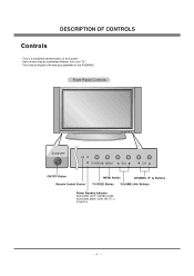
This is turned on the P42W46X. Here shown may be somewhat different from your TV. - This manual explains the features available on . -4- DESCRIPTION OF CONTROLS Controls - Front Panel Controls ON/OFF TV/VIDEO MENU VOL CH ON/OFF Button Remote Control Sensor MENU Button CHANNEL (E, D) Buttons TV/VIDEO Button VOLUME (F,G) Buttons Power Standby Indicator Illuminates red in standby mode, Illuminates green when the TV is a simplified representation of front panel.
This is turned on the P42W46X. Here shown may be somewhat different from your TV. - This manual explains the features available on . -4- DESCRIPTION OF CONTROLS Controls - Front Panel Controls ON/OFF TV/VIDEO MENU VOL CH ON/OFF Button Remote Control Sensor MENU Button CHANNEL (E, D) Buttons TV/VIDEO Button VOLUME (F,G) Buttons Power Standby Indicator Illuminates red in standby mode, Illuminates green when the TV is a simplified representation of front panel.
Service Manual
Page 6
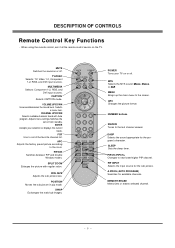
... 1-2, RGB, and DVI input sources. WIN. POSITION Moves the sub picture in pip mode. Adjusts menu settings.Switches the set on the TV. APC Adjusts the factory preset picture according to the last channel viewed. SPLIT ZOOM Enlarges the picture with Auto program. SWAP Exchanges the main.../sub images. PIP INPUT POSITION SWAP A.PROG MEMORY/ERASE POWER Turns your selection or displays the current mode. MTS Selects the MTS sound: Mono, Stereo, or SAP. DASP Selects the sound appropriate for...
... 1-2, RGB, and DVI input sources. WIN. POSITION Moves the sub picture in pip mode. Adjusts menu settings.Switches the set on the TV. APC Adjusts the factory preset picture according to the last channel viewed. SPLIT ZOOM Enlarges the picture with Auto program. SWAP Exchanges the main.../sub images. PIP INPUT POSITION SWAP A.PROG MEMORY/ERASE POWER Turns your selection or displays the current mode. MTS Selects the MTS sound: Mono, Stereo, or SAP. DASP Selects the sound appropriate for...
Service Manual
Page 8
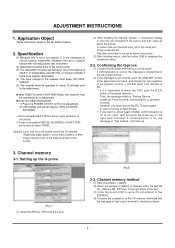
...the message which is activated HEAT-RUN without signal generator in the right blank of the File. (3) Click the button [OK] to check PANEL. If communication is on or not, input "test" and push the Enter key on , the message of HEAT-RUN mode uses to write...for adjustment. 2) OSD display and screen display 100% full WHITE PATTERN. [ Set is "Starting Gprove..." Confirming the G-prove (1) Connect Rs232 cable and then turn on the power. Channel memory method (1) Click [Command -> Batch]. (2) When the window of [Batch] is operated correctly. Specification (1) Because this time, ...
...the message which is activated HEAT-RUN without signal generator in the right blank of the File. (3) Click the button [OK] to check PANEL. If communication is on or not, input "test" and push the Enter key on , the message of HEAT-RUN mode uses to write...for adjustment. 2) OSD display and screen display 100% full WHITE PATTERN. [ Set is "Starting Gprove..." Confirming the G-prove (1) Connect Rs232 cable and then turn on the power. Channel memory method (1) Click [Command -> Batch]. (2) When the window of [Batch] is operated correctly. Specification (1) Because this time, ...

Service Manual
Page 9
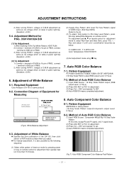
terminal to GND pin of P805. 3) After turning RV501, voltage of D.M.M adjustment as same as below. < 3501V00180A > (Fig 4) < 3501V00182A > (Fig 5) Connection Diagram of P805, connect - HDCP download 4-1. HDCP download method (1) Click [Command -> NVRAM ... EEPROM. (6) It means the end of the HDCP key download that the message of Output terminal is showed as Va voltage which on lable of panel right/top (Deviation; ±0.5V) (2) Vs Adjustment 1) Connect + terminal of D.M.M to write HDCP key in the File. (3) LGEKEY1 : first KEY value (4) Address : insert '0' (5) After finishing...
terminal to GND pin of P805. 3) After turning RV501, voltage of D.M.M adjustment as same as below. < 3501V00180A > (Fig 4) < 3501V00182A > (Fig 5) Connection Diagram of P805, connect - HDCP download 4-1. HDCP download method (1) Click [Command -> NVRAM ... EEPROM. (6) It means the end of the HDCP key download that the message of Output terminal is showed as Va voltage which on lable of panel right/top (Deviation; ±0.5V) (2) Vs Adjustment 1) Connect + terminal of D.M.M to write HDCP key in the File. (3) LGEKEY1 : first KEY value (4) Address : insert '0' (5) After finishing...
Service Manual
Page 10
terminal to GND pin of P805. 3) After turning RV601, voltage of D.M.M adjustment as same as Va voltage which on reomte control for adjustment mode to Vs pin of P805, connect - Adjustment of P805, connect - For adjustment and D, E on lable of panel right/top (Deviation; ±0.5V) (2) Vs ...Scale Pattern At this time, except Pb and Pr signal, only Y signal insert. (2) Press ADJ KEY on label of panel right/top. (Deviation; ±0.5V) 5-4. ADJUSTMENT INSTRUCTIONS 2) After turning RV401, voltage of D.M.M adjustment as same as Va voltage which on R/C for adjustment. (3) Press Vol. + KEY and...
terminal to GND pin of P805. 3) After turning RV601, voltage of D.M.M adjustment as same as Va voltage which on reomte control for adjustment mode to Vs pin of P805, connect - Adjustment of P805, connect - For adjustment and D, E on lable of panel right/top (Deviation; ±0.5V) (2) Vs ...Scale Pattern At this time, except Pb and Pr signal, only Y signal insert. (2) Press ADJ KEY on label of panel right/top. (Deviation; ±0.5V) 5-4. ADJUSTMENT INSTRUCTIONS 2) After turning RV401, voltage of D.M.M adjustment as same as Va voltage which on R/C for adjustment. (3) Press Vol. + KEY and...
Service Manual
Page 11
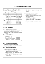
... (D-Sub 15Pin). 3) Operate S/W for DDC record and select DDC data for digital RGB in DOS mode.) 10-4. Preparation for Adjustment (1) Set devices as above and turn the power on . (2) Put S/W for writing DDC (EDID data Write & Read) into operation. (operated in model menu. 3) Operate EDID Write command. 4) Operate ...command and check whether Check Sum is 53. - 11 - Sequence of Adjustment (1) DDC Data Input for Analog-RGB 1) Put the set on the table and turn the PC, jig on . 2) Connect PC Serial to DVI Jack) 10-2. Required Test Equipment (1) A jig for adjusting PC, DDC (PC serial to D-...
... (D-Sub 15Pin). 3) Operate S/W for DDC record and select DDC data for digital RGB in DOS mode.) 10-4. Preparation for Adjustment (1) Set devices as above and turn the power on . (2) Put S/W for writing DDC (EDID data Write & Read) into operation. (operated in model menu. 3) Operate EDID Write command. 4) Operate ...command and check whether Check Sum is 53. - 11 - Sequence of Adjustment (1) DDC Data Input for Analog-RGB 1) Put the set on the table and turn the PC, jig on . 2) Connect PC Serial to DVI Jack) 10-2. Required Test Equipment (1) A jig for adjusting PC, DDC (PC serial to D-...


