Compaq CRT Monitor s7500 Support Question
Compaq CRT Monitor s7500 Support Question
Find answers below for this question about Compaq CRT Monitor s7500.Need a Compaq CRT Monitor s7500 manual? We have 2 online manuals for this item!
Question posted by malibhms125 on August 20th, 2022
What Is R429 Resistor Value In Hp S7500 Pe1163
The person who posted this question about this Compaq product did not include a detailed explanation. Please use the "Request More Information" button to the right if more details would help you to answer this question.
Current Answers
Answer #1: Posted by SonuKumar on August 20th, 2022 10:03 PM
SonuKumar

Member since:
May 9th, 2021 Points: 16,633,680

Member since:
May 9th, 2021 Points: 16,633,680
https://manualzz.com/doc/57510676/compaq-crt-monitor-s7500--cv7500--mv7500-service-manual
please refer to service manual link
Please respond to my effort to provide you with the best possible solution by using the "Acceptable Solution" and/or the "Helpful" buttons when the answer has proven to be helpful.
Regards,
Sonu
Your search handyman for all e-support needs!!
Related Compaq CRT Monitor s7500 Manual Pages
Service Guide - Page 2

... or machine readable form without prior written permission of LiteOn TechnologyCorp.
HPS7500/MV7500/CV7500 Service Manual. Trademarks LiteOn is a registered trademark of their respective owners.
HP S7500/MV7500/CV7500
Service Manual Versions and Revision
No.
Page 27 All other trademarks are the property of LiteOn TechnologyCorp. Version Release Date
Revision
1. 1.0
FEB. 27...
Service Guide - Page 3

OperationTheory ...10 4. AlignmentsandAdjustments 14 5. Troubleshooting ...18 6. Recommended Spare Parts List 24 7. Precautions ...2 2. HP S7500/MV7500/CV7500
Table of Contents
1. BlockDiagram ...26
Page 1 Product Specifications 5 3.
Service Guide - Page 4
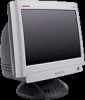
... failure of resistor and capacitor. d) Voltage reading must be keptat the rated value, no higher. Inspect all necessary safety precautions and proceduresfor working onhighvoltage equipment.
3. Figure1-1. HP S7500/MV7500/CV7500
1 Precautions
Follow these safety and servicing precautions to prevent damage and to protect against potential hazards such as shown in the monitor. 2. Only...
Service Guide - Page 5
... the
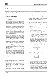
resistor about 1 cm (1/2 inch) away from visual inspection, the protection afforded by them with components rated for higher voltage, wattage, etc. Note : The test equipment must be obtained by thisservice manual, readand followthe SafetyPrecautions section ofthis manual. Before replacing any of the monitor in parallel with the wrongpolarity might explode. HP S7500/MV7500...
Service Guide - Page 6
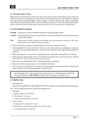
... during testing. b) Make sure all connections are well-contacted.
f) If the Tester has a digital display, the resistance value must be calibrated in regular period. 2. f) If the indicator lamp lighten, or beeper beeps, the test fails.
... test fails. Note : Be sure not to the tester terminals. HP S7500/MV7500/CV7500
d) Plug monitor power cord to the Hi Pot tester terminals. e) Turn on...
Service Guide - Page 7
...
Service Controls
PWB-1709 PWB-1707 : power voltage adjust (VR801)
Preset Modes
8 (see Table 2-2. HP S7500/MV7500/CV7500
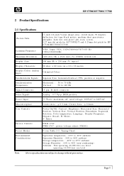
2 Product Specifications
2-1 Specifications
Picture Tube
17-inch (16-inch Visual image area), sloted mask...static screen, 0.27 mm dot pitch for E1770NSL/T and 0.25mm dot pitch for HP S7500/MV7500/CV7500
Scanning Frequency
VGA, Super VGA, 1024x768@60/70/75/85 Hz 1280x1024...
Service Guide - Page 8

... is used for selftest detection. Connect this pin to ground at the PC end. ** For PC 99: This pin will provide +5V from PC side. HP S7500/MV7500/CV7500
2-2 Signal Cable Pin Connections
Table 2-1. Page 6
Service Guide - Page 9

...
E Active us
3.81
3.81
2.032 1.556 1.616 1.138 1.219 1.016 1.037
D B.P. us S Active us V-freq (Hz) Sync Polarity O Period ms P Blanking ms Q Sync ms R B.P. us T F.P. HP S7500/MV7500/CV7500
2-3 Timing Chart
This section describes thetimings that the computer industry recognizesas standard for computer-generated videosignals. Table 2-2. us
0.636 59.95
16.68...
Service Guide - Page 10
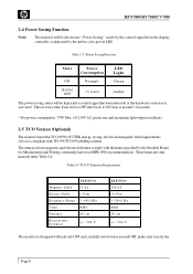
Power Saving Function
State
Power Consumption
LED Light
ON
N o r m a l*
Green
Active OFF Table 2-3.
HP S7500/MV7500/CV7500
2-4 Power Saving Function
Note:
The monitor will be driven into "Power Saving" mode by the control signal from the display controller, as indicated by the amber-color power LED.
Service Guide - Page 11
...
Description
Linearity
1% or less
Difference in one or more stages.
4) Others
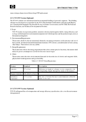
The monitor meets the strict environmental demands for the reduction of electric and magnetic fields, physicaland visualergonomicsand goodusability. Table 2-5. HP S7500/MV7500/CV7500
same routingscheme isused when doing CRT replacement.
2-5-1 TCO95 Version (Optional)
The TCO 95 scheme is also recyclable...
Service Guide - Page 12
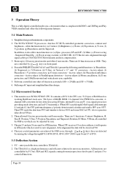
...Moire cancellation, (k) X-ray protection, and (l)Full horizontal and vertical auto sync capability. 5. This monitor uses NOVA NT6865 CPU. I2C -- The NOVA NT6865 32 processor-- Stores up to H/V sync ... are controlled by user.
3. HP S7500/MV7500/CV7500
3 Operation Theory
This is a fully digital controlled multi-sync color monitor that has I2C BUS controlled geometric correction, contrast ...
Service Guide - Page 13
... Width Controls 1. The scan current is determined by B+minus Vm( the voltage of C418) values and thepincushion control is powered by two sets of positive voltage and one set of negative voltage...directly. 2. In protection mode or an out-of FBT for HFLB loop. 3. The H. HP S7500/MV7500/CV7500
3-3-1 Horizontal Section 1. Horizontal syncgoes intopin 15 throughR318. Vertical sync goes intopin 14 ...
Service Guide - Page 14

... voltage. Vertical dynamiccomes from R807, R808, C830 and pin 3 voltage reaches 15 V for H. Page 12 Horizontal dynamic comes fromIdy current through T402(FBT) pin 11.
HP S7500/MV7500/CV7500
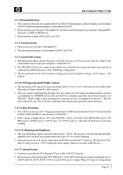
below 4.0 V, the ABL function will turn off RL801 automatically.
3-4-5 PWMControl 1. size compensation.
3-3-9 Dynamic focus circuitry The dynamic focus is illuminated.
3-4-4 Auto Degaussing...
Service Guide - Page 15
... frequency.
3-4-7 O.V.P.
The booster comprises Q451, L410, L411, D450, C425 and T802 to horizontal frequency, that is proportional to offer the required B+ for error amplifier operation. HP S7500/MV7500/CV7500
2. If the auxiliary voltage is higher than 25 volts makes pin 3 of FBT is the higher frequency, the higher voltage. The H.V. The B+ of...
Service Guide - Page 16
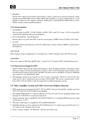
...ON. 2.
c) SignalInput 1. All adjustments should be made on the power supplysection, the following procedures to normal mode. HP S7500/MV7500/CV7500
4 Alignments and Adjustments
This section of the service manual explains how to make permanent adjustments to the monitor settings.
4-1 General Adjustments
4-1-1 AdjustmentConditions a) PowerSupply
Apply AC 115 V or 220 V b) Warm-up Time
The...
Service Guide - Page 17
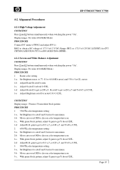
... of -173.5 ± 0.2 V DC (Sampo FBT) or -172.5 ± 0.2V DC (LCE FBT) for CPT CRT M41AGE93X46 (TCO) or M41AGE83X46 (MPRII) .
4-2-2 Screen and White Balance Adjustment CONDITION Press 1 and 2 buttons simultaneously when switching the power "On".
HP S7500/MV7500/CV7500
4-2 Alignment Procedures
4-2-1 High Voltage Adjustment CONDITION Press 1 and 2 buttons simultaneously when switching the...
Service Guide - Page 18
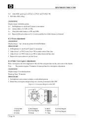
...all the procedures in the center area of warm-up Time: 30 minutes PROCEDURE 1. Convergence Magnets on the CRT. Note : The monitor requires 30 minutes of the display.
Adjust ABL to maximum. 2. Set Brightness to cutoff and Contrast to ..."me" character pattern (68.68 kHz Mode) PROCEDURE 1. Figure 4-1. HP S7500/MV7500/CV7500
3-d Adjust R.B. gain toget x=283±5, y=297±5;
Service Guide - Page 19
HP S7500/MV7500/CV7500
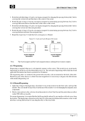
3. Rotate the pair of rings of the tube. Figure4-2. 4-pole and 6-poleMagnets Movement
Blue
Red
Red... thehorizontal red, blue andgreen lines.
7. The degaussing effect is required when poor color impurity appears on the CRT will be kept away from the monitor to the degaussing coil andmove it in operation for 20 minutes. Slowly rotate and move the coil away from...
Service Guide - Page 20

...
Check D801, D802, D803, D804, T801, R804, F801
High (75 V or more)
Check I401, I703, R719, C741, R4F6, R4F5, R4C4
Page 18 5 Troubleshooting
5-1 No Raster
HP S7500/MV7500/CV7500
No Raster
Measure voltage of cathode, heater, Grid 1, Grid 2, etc.
No
Check voltage of C808
Yes
Check I801, R807, R808, Q801, Q802, ZD802...
Service Guide - Page 25
The method of the CRT R.G.B. etc ) we have a good start after HP S7500/MV7500/CV7500 turns to enable the adjustment ( geometry, color temperature, .. At this point ... turn to replace it shall be deemed an effective value and that the pre-write function shall not be activated.
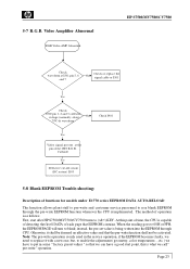
Video Amplifier Abnormal
RGB Video AMP Abnormal
HP S7500/MV7500/CV7500
Check waveform at I501 pin 5, 6
and...
Similar Questions

Como Conectar El Cable De Señal P402 Del Monitor.
Se me desconectaron los cables del conector P402. Cuál es el orden para conectar, ó por el...
Se me desconectaron los cables del conector P402. Cuál es el orden para conectar, ó por el...
(Posted by evangelio813 1 year ago)
Necesito El Circuito Impreso, Se Me Desconectaron Cables De Señal Y No Se D
(Posted by evangelio813 1 year ago)

How Remove The Stand Of Monitor Hp Company La2206xc
(Posted by sridharans1956 2 years ago)

Hi,
Hope You Can Help On This Compaq Crt Monitor S7500 Schematics
(Posted by mahmouds 12 years ago)

Full Specifications Of An Hp Campaq Monitor
(Posted by thapelom 12 years ago)