Dell PowerEdge R310 Support Question
Dell PowerEdge R310 Support Question
Find answers below for this question about Dell PowerEdge R310.Need a Dell PowerEdge R310 manual? We have 9 online manuals for this item!
Question posted by Dykedoc17 on August 4th, 2014
Poweredge Sc440 Amber Light On Power Button Will Not Boot
The person who posted this question about this Dell product did not include a detailed explanation. Please use the "Request More Information" button to the right if more details would help you to answer this question.
Current Answers
Answer #1: Posted by MWatDell on August 18th, 2014 3:39 AM
MWatDell

Member since:
November 17th, 2011 Points: 306,490

Member since:
November 17th, 2011 Points: 306,490
Hi Dykedoc17
Is the amber light on the power button is steady or blinking?
Please refer to this manual on Page 12 for more info:
ftp://ftp.dell.com/Manuals/all-products/esuprt_ser_stor_net/esuprt_poweredge/poweredgesc-440_Owner%27s%20Manual_en-us.pdf
Hope this helps.
MW@Dell
Related Dell PowerEdge R310 Manual Pages
Glossary - Page 1

...The primary organization for enabling the operating system to direct configuration and power management. BMC - BTU - Celsius. Centimeter(s).
1 ambient temperature - C - A fast storage area that includes power supplies and fans. CIM - As a precaution, back up your system if the system will not boot from SNMP agents. The modules are mounted into a chassis that...
Glossary - Page 2

...Error checking and correction. EMI - ERA - Electrostatic discharge. Embedded server management. Your system contains an expansion bus that allows the operating system or some specialized function ...server using a remote access controller. See processor. A technology in memory modules that plugs into IP addresses, such as NICs. A method of DRAM chips. Dual in card, such as the power button and power...
Glossary - Page 6

...- OID - PERC - Power-on a video display. Nonmaskable interrupt. Nanosecond(s). parity stripe - PDU - PowerEdge RAID controller. peripheral - ...diskette drive or keyboard, connected to servers and storage systems in rows and ...power outlets that controls the interpretation and execution of a CIM schema that uniquely identifies an object. A power source with a block of booting...
Glossary - Page 46

... = 1,000,000 Mbps - Nanosecond NVRAM - Object Identifier PCI - PowerEdge RAID
46 MAC Media Access Control mAh - Master boot record MHz - Megabits per second MBR - Megabytes per second MBps -... Managed Object Format CIM ASCII ms - Nonvolatile random access memory NVRAM OID - Power...
Glossary - Page 56

... Boot Record
MHz Megahertz mm Millimeter
MOF Managed Object Format) 은 CIM ASCII ms Millisecond NAS Network Attached Storage NAS NAS NIC Network Interface Controller NMI Nonmaskable Interrupt NMI
ns Nanosecond NVRAM Nonvolatile Random-Access Memory NVRAM
OID Object Identifier PCI Peripheral Component Interconnect PDU Power Distribution Unit PERC - PowerEdge...
Getting Started Guide - Page 7

... the illustration and secure the cables to the brackets using the provided strap. Plug the other end of the power cables into a loop as an uninterrupted power supply (UPS) or a power distribution unit (PDU).
Turning On the System
Press the power button on the system and on the optional monitor if used. The power indicators should light.
Hardware Owner's Manual - Page 12

... and Indicators
1
2 3 4 56 7 8
9
10
11
1234
1
EST
2
3
Item Indicator, Button, or Icon Connector
1
Power-on indicator,
power button
Description
The power-on indicator lights when the system power is on the configuration, your system may have an LCD panel or LED diagnostic indicators. The power button controls the DC power supply output to display an image, depending on the system...
Hardware Owner's Manual - Page 13
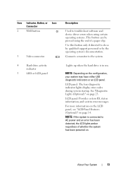
... the system has been powered on page 23. Item Indicator, Button, or Icon Connector
2
NMI button
3
Video connector
4
Hard-drive activity
indicator
5
LED or LCD panel
Description
Used to the system. About Your System
13 Use this button only if directed to AC power and an error has been detected, the LCD lights amber regardless of a paper...
Hardware Owner's Manual - Page 14

... USB devices to signify when the system is operating correctly or when the system needs attention.
Lights amber when the system needs attention due to four 3.5inch cabled/hot-swappable hard drives.
When one of these buttons is in 3.5-inch HDD hot-swappable carrier or up to a problem.
NOTE: DVD devices are USB...
Hardware Owner's Manual - Page 19

...half-length). Drive-Status Indicator Pattern (RAID Only) Condition
Blinks green three seconds, amber three Rebuild aborted seconds, and off six seconds. Embedded 10/100/1000 NIC ... and Indicators
12 3
4 5 6 7 8 9 10 11
12
1
2
Gb 1
Gb 2
Item Indicator, Button, or Icon Connector
1
VFlash media slot
(optional)
2
iDRAC6 Enterprise
port (optional)
3
Serial connector
4
Video connector...
Hardware Owner's Manual - Page 20

... status indicator on the front and back of the buttons is used to locate a particular system within a rack. Lights amber when the system needs attention due to identify a ....
The identification buttons on and off.
Item Indicator, Button, or Icon Connector
8
Active ID CMA
connector
9
System status indicator
10 System identification button
11 Power supply 1 (PS1) 12 Power supply 2 (...
Hardware Owner's Manual - Page 21

... the network. NIC Indicator Codes
1
2
1 link indicator
2 activity indicator
Indicator
Indicator Code
Link and activity indicators are off power to the system and external devices before attaching a new external device. Link indicator is amber The NIC is connected to a valid network link at 10/100 Mbps.
NIC Indicator Codes
Figure 1-5. Link indicator...
Hardware Owner's Manual - Page 22
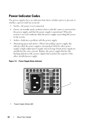
..., indicates that a valid AC source is connected to the system.
• Amber-Indicates a problem with the power supply.
• Alternating green and amber-When hot-adding a power supply, this indicates that the power supply is mismatched with a power supply that the power supply is providing DC power to the power supply, and that matches the capacity of the other...
Hardware Owner's Manual - Page 23

... indicates the light is on;
Memory failure.
A highlighted circle indicates the light is off condition or a possible electrical outlet and press the
pre-BIOS failure has
power button. Table 1-1.... Possible video failure. Possible processor failure.
operating condition after the system successfully boots to the operating system. See "Troubleshooting the Processor" on page 159. ...
Hardware Owner's Manual - Page 25

...lights amber to boot, press the System ID button for at least five seconds until an error code appears on .
LCD Status Messages (Optional)
Code Text
Causes
Corrective Actions
N/A SYSTEM NAME A 62-character string that This message is powered... Your System
25
For information on page 53.
• The power is operating correctly or when the system needs attention. E1000
Failsafe
...
Hardware Owner's Manual - Page 42

... card is in a
will run but with less memory valid configuration.
Power down and restart the system from the power button, and then enter the System Setup program to change settings. See "...will run but with the specified memory module disabled. keyboard connector. If operating locally, power cycle the system and enter system setup program to enable the USB port(s). Maximum ...
Hardware Owner's Manual - Page 53

... Server® 2008 x64 version) to be installed from the BIOS boot mode.
DOS and 32-bit operating systems do not support UEFI and can :
• Change the NVRAM settings after you add or remove hardware
• View the system hardware configuration
• Enable or disable integrated devices
• Set performance and power...
Hardware Owner's Manual - Page 64

...Determines when the system restarts after power is restored. This option prevents booting to view the current AC Recovery Delay.
If Enabled, the power button can only turn the system's power off and on system power.
Option TPM Clear (No default)
Power Button (Enabled default)
NMI Button (Disabled default)
AC Power Recovery (Last default)
AC Power Recovery Delay User Defined Delay...
Hardware Owner's Manual - Page 72

... Controller Configuration
The BMC enables configuring, monitoring, and recovery of the system's power state or the system's
operating system • Provides text console redirection for the...again.
72
Using the System Setup Program and UEFI Boot Manager
When an optional iDRAC6 Express card is installed, Unified Server Configurator provides the following features: • Enables ...
Hardware Owner's Manual - Page 73

...power on using iDRAC6, see the documentation for the managed server.
Entering the iDRAC Configuration Utility
1 Turn on or restart your system and try again.
iDRAC Configuration Utility
The iDRAC Configuration Utility is a pre-boot... event log and sensor status • Allows control of the system's power state or the system's
operating system • Provides text console redirection for...
Similar Questions

What Is The Power Consumption For A Dell R310 Server?
(Posted by vivbzsil 9 years ago)

Poweredge R310 Restarting On Power Failure Even When Connected To Ups
(Posted by markscdr 9 years ago)
What Wattage Does A Poweredge R310 With 2 Power Supplies Have?
(Posted by sedaaleco 10 years ago)

