Sony HCD-EC50 Support Question
Sony HCD-EC50 Support Question
Find answers below for this question about Sony HCD-EC50 - Cd Deck Receiver Component.Need a Sony HCD-EC50 manual? We have 1 online manual for this item!
Question posted by moparautoranch on October 29th, 2012
Replacement Parts.
I have lost my antenna off my stereo. Where would I find a replacement
Current Answers
Related Sony HCD-EC50 Manual Pages
Service Manual - Page 1

...AUDIO IN (stereo mini jack): Sensitivity 800 mV, impedance 47 kilohms Outputs PHONES (stereo mini jack): Accepts headphones with 7mm aperture.
COMPACT DISC DECK RECEIVER
9-879-904-04
2006C16-1 © 2006.03
Sony Corporation
Personal Audio Division Published by Sony Techno Create Corporation CD....03
HCD-EC50
US Model Canadian Model
AEP Model UK Model E Model
Australian Model
HCD-EC50 is the...
Service Manual - Page 3

... 1 SERVICING NOTES
HCD-EC50
CAUTION Use of controls or adjustments or performance of procedures other exposed metal parts for AC leakage...may also be set to the customer: Check the antenna terminals, metal trim, "metallized" knobs, screws, ...to protect the CD mechanism. 2 Hold down CD u (play/pause) on chip component replacement • Never reuse a disconnected chip component. • Notice...
Service Manual - Page 4

... !TO: NUMBERSTO ANDSYMBOLS@
n
5SINGOPTIONALAUDIO COMPONENTS
4OCONNECTANOPTIONALHEADPHONES #ONNECTHEADPHONESTOTHE0(/.%3JACKȴONTHE UNIT
4OCONNECTANOPTIONALCOMPONENT #ONNECTADDITIONALAUDIOSOURCECOMPONENTSTOTHE !5$)/).JACKȵONTHEUNITUSINGANAUDIOCORDNOT SUPPLIED 4URNDOWNTHEVOLUMEONTHESYSTEM ANDTHEN SELECTTHE!5$)/).FUNCTION
4 HCD-EC50
SECTION 2 GENERAL
This section is...
Service Manual - Page 5

...4vAPPEARS ANDTHENPRESS
nOR45.).'
ORnONTHEUNIT ȯREPEATEDLYTOTUNEINTHEDESIRED STATION
0RESS45.%2-%-/29ȹONTHEREMOTE
0RESETNUMBER
0RESS
nOR45.).'
HCD-EC50
/THER/PERATIONS
#REATINGYOUROWN#$PROGRAM
0ROGRAM0LAY
5SEBUTTONSONTHEREMOTETOCREATEYOUROWNPROGRAM
0RESS#$ȭTOSELECTTHE#$FUNCTION 0RESS0,!9-/$%ȹREPEATEDLYUNTILh0'-v
APPEARSWHILETHEPLAYERISSTOPPED
0RESS...
Service Manual - Page 12

... head
rubber belts
capstan
idlers
2.
After the adjustments, apply suitable locking compound to
the parts adjusted.
5. Do not use a magnetized screwdriver for the adjustments.
4. Do not use...oz)
DECK SECTION 0 dB=0.775 V
1. Mode: Playback
test tape P-4-A063 (6.3 kHz, −10 dB)
JACK board
PHONES jack
(J102)
level meter
set
waveform of peak. HCD-EC50 SECTION 4...
Service Manual - Page 13

... Head
HCD-EC50
CD SECTION
Note: 1. Connect oscilloscope to TP (RFACI) and TP (VC) on the tray and press the CD u button to playback. 4. VOLT/DIV: 200 mV TIME/DIV: 500 ns
level: 0.9 ± 0.4 Vp-p
Checking Location: - Procedure : 1.
Clean the object lens by an applicator with neutral detergent when the signal level is replaced. Use...
Service Manual - Page 15

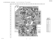
MAIN BOARD (Conductor Side) -
1
CNP802
ANTENNA
3
TP(TUNER-VT)
IC801
36
19
12
1
18
IC801 pin qs (TUNER OUT L-ch)
TP(TUNER-GND)
HCD-EC50
15 Adjustment Location and Connecting Points - MAIN BOARD (Component Side) -
TUNER-VT
AM Tracking Adjustment
L851
FM Frequency Coverage Adjustment
AM Frequency Coverage Adjustment
L805
L852 L804
L806
FM Tracking...
Service Manual - Page 16

...E model
KR : Korean model
SP : Singapore model
Note on the parts face side seen from the side which enables seeing. C
Q
These are in Ω and 1/4 W or less unless otherwise
specified.
• f : internal component. • 2 : nonflammable resistor. • 5 : fusible resistor. • C : panel designation. HCD-EC50
Ver. 1.3
SECTION 6 DIAGRAMS
THIS NOTE IS COMMON FOR PRINTED WIRING...
Service Manual - Page 18
.../LED6/TOT1 23
CD-L
MAIN
A SECTION
CD-R
(Page 20)
Q669,670 MOTOR DRIVE Q671,672 MOTOR DRIVE
Q665,666 MOTOR DRIVE Q667,668 MOTOR DRIVE
CD MECHANISM DECK BLOCK
SW3 SW1 SW7(CHACK) SW2 SW6(CLOSE) SW5(STOC) SW8(OPEN)
+
M M1
-
+
M M2
-
Q661-664
CD MOTOR CONTROL
VM9V
• Signal Path : CD
HCD-EC50
18
18 HCD-EC50
6-1. BLOCK DIAGRAM...
Service Manual - Page 20
HCD-EC50
Ver. 1.3
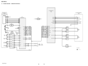
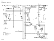
6-3. BLOCK DIAGRAM - MAIN SECTION - J105 AUDIO IN
R-CH
B
TUNER SECTION (Page19)
+9V
L-CH R-CH
TU-DO TU-DI TU-CLK TU-CE TU-ANSD
+9V R-CH
TAPE MECHANISM DECK BLOCK
SW501(1/2) (REC/PB)
L-CH
REC/PB HEAD
R-CH
R-CH
SW501(2/2) (REC/PB)
L501 BIAS OSC
BIAS OSC Q507
P-SW M
VM9V
M-SW
A
CD-L
CD...P34/IC0 9
IC703
REMOTE 1 CONTROL 3
RECEIVER
D702
P66/AN6/INT1 42 RSTX 54
Q704
...
Service Manual - Page 23
... (REC/PB)
TAPE MECHANISM
DECK
JACK BOARD
J105 AUDIO IN
1 (CHASSIS)
J102
8
PHONES
11 1-868-531-
(11)
• Semiconductor Location
Ref.
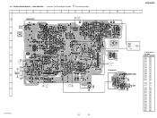
PRINTED WIRING BOARD - MAIN SECTION - • See page 17 for Circuit Boards Location.
:Uses unleaded solder.
1
2
3
4
5
6
7
8
HCD-EC50
9
A
MAIN BOARD
AMP BOARD
C WH102
(Page 29)
B
CNP802 ANTENNA
FM/AM
CF802,CF803
C
D
B
AMP...
Service Manual - Page 27
...C-3 Q704 B-3 Q705 B-3 Q706 B-3 Q707 B-3
6-10. No. CD MECHNISM
DECK
E
E
E
E
E
E
E
E
DISC 3
PLAY MODE TUNING MODE
EQ
B C
A
ROTARY ENCODER VOLUME
E
A/K KA E
E E
DISC 2
DISC 1
26 27
21
DISC SKIP/ EX-CHANGE
D MAIN BOARD CNS111 (Page 23)
SW701 - 706, SW708 - 716, SW719 - 721
11
1-868-529-
(11)
HCD-EC50
27
27
HCD-EC50
• Semiconductor Location
Ref. PANEL SECTION...
Service Manual - Page 38

...Part No.
No.
2 3 3 4
Part No. Replace only with mark 0 are critical for routine service. OVERALL SECTION
• The mechanical parts...
The components identified by mark 0 or dotted line with part number ...
chassis section, CD section and
Base unit (BU-K6BD83S-WOD) section
Ref. HCD-EC50
Ver. 1.3
SECTION 7 EXPLODED VIEWS
NOTE: • -XX and -X mean standardized parts, so they
...
Service Manual - Page 40
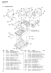
...ACW001 1-832-377-11 CORD, POWER (E3)
M901 1-787-396-11 D.C. No. 109 110
Part No. FAN (50 SQUARE) (E3, SP, KR, AUS) 0 PT001 1-443-845-11... 106 107
107 107 107 108 109
109 109 109
40
Part No.
Description
Remark
2-649-153-01 CHASSIS (MAIN MOLD) ...(AUS) A-1169-540-A PT BOARD, COMPLETE (AEP, UK, CET)
Ref. HCD-EC50
Ver. 1.3
7-3. CHASSIS SECTION
107 102
102 102
not supplied
108
not supplied ...
Service Manual - Page 41
....
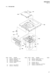
158 158 159
Part No. Description
4-951-620-01 2-649-154-01 2-649-132-01 3-921-725-01 3-047-468-01
SCREW (2.6X8), +BVTP LEVER (REC) BUTTON (CASS) SCREW (2.6X10), +PWH DAMPER
156 2-649-131-01 BOX, CASSETTE 157 2-649-152-01 SPRING (CASS)
Remark
Ref.
TOP SECTION 156
HCD-EC50
Ver. 1.3
157...
Service Manual - Page 42
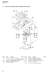
... SPRING (INSULATOR), COIL 4-227-549-11 INSULATOR
Ref. No.
206 207 208 0 209 210
S201
Part No. HCD-EC50
Ver. 1.3
7-5.
No. 201
201 202 204 205
Part No.
Description
Remark
4-951-620-01 SCREW (2.6X8), +BVTP 1-797-193-12 MECHANICAL, CD (DLM3A23-11) 1-827-992-11 WIRE (FLAT TYPE) (16 CORE) A-4735-357-A OP BASE...
Service Manual - Page 43
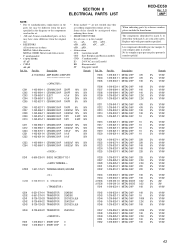
... with mark 0 are critical for safety. SECTION 8 ELECTRICAL PARTS LIST
HCD-EC50
Ver. 1.3 AMP
NOTE: • Due to standardization, replacements in the
parts list may have some difference from the parts specified in the diagrams or the components used on the set. • -XX and -X mean standardized parts, so they
are seldom required for example:
uA. . : µA. .
Les...
Service Manual - Page 52
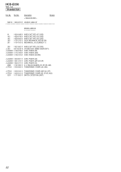
... WIRE (FLAT TYPE) (13 CORE)
105 1-828-643-21 WIRE (FLAT TYPE) (23 CORE)
159 1-797-375-11 DECK, MECHANICAL (H21SB-C05)
207 1-797-193-12 MECHANICAL, CD (DLM3A23-11)
208 1-827-992-11 WIRE (FLAT TYPE) (16 CORE) 0 209 A-4735-357-A OP BASE ASSY (..., UK, CET) 1-443-911-11 TRANSFORMER, POWER (E3, SP, KR, AUS) 1-771-853-11 SWITCH, DETECTION (LIMIT)
52 Part No. HCD-EC50
Ver. 1.3
TRANSISTOR
Ref.
Service Manual - Page 55
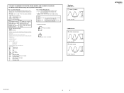
...F : TUNER (FM)
f : TUNER (AM)
J : CD
d : AUX
E : PB (TAPE)
a : REC ...
239 ns 1 V/DIV, 100 ns/DIV
2.9 Vp-p
HCD-EC50
3
3
HCD-EC50
Ver. 1.3 Note: The components identified by mark 0 or dotted line with part number specified. Line.
• Voltages are indicated. BD... DIAGRAMS. (In addition to waveforms.
• Signal path. Replace only with mark 0 are in µF unless otherwise noted...
Service Manual - Page 67

... CHIP 22K
5% 1/10W
15 ELECTRICAL PARTS LIST
HCD-EC50
Ver. 1.3
AMP
NOTE:
• Due to standardization, replacements in the
parts list may be anticipated when
ordering these items.
• SEMICONDUCTORS
In each case, u: µ, for routine service. Some delay should be different from the parts
specified in the diagrams or the components
used on the set.
•...
Similar Questions

Sony Compact Disc Deck Receiver Model No. Hcd-zx6 Power Light Flashing.
please i need help getting this system working. I paid a lot of money for this system lol
please i need help getting this system working. I paid a lot of money for this system lol
(Posted by true2dan0ne 3 years ago)

Where To Buy A Sony 265 Watt Compact Disc Deck Receiver Hcd-gx450
(Posted by jenkyml 10 years ago)

How Much Sony Compact Disc Deck Receiver, Hcd 541
(Posted by golal 10 years ago)

Where Can I Get A Manual For My 2004 Sony Model Hcd-hpx9 Cd Deck Receiver?
DSGX. 5+1 Disc changer w/cassette (yes, cassette) on top. I know, obsolete. Not listed on Sony's cit...
DSGX. 5+1 Disc changer w/cassette (yes, cassette) on top. I know, obsolete. Not listed on Sony's cit...
(Posted by heccher88 12 years ago)

What Is The Value Of The Sony Hcd-lx50 Compact Disk Deck Receiver ?
How much id the Sony HCD-LX50 compact disk deck receiver worth?
How much id the Sony HCD-LX50 compact disk deck receiver worth?
(Posted by Strong 13 years ago)