Sony HCD-SH2000 Support Question
Sony HCD-SH2000 Support Question
Find answers below for this question about Sony HCD-SH2000.Need a Sony HCD-SH2000 manual? We have 1 online manual for this item!
Question posted by calebloganph on November 28th, 2018
How To Fix Protect
my device turns on fully but wont play and screen reads protect
Current Answers
Answer #1: Posted by Odin on November 28th, 2018 4:06 PM
Odin

Member since:
April 10th, 2010 Points: 41,236,620

Member since:
April 10th, 2010 Points: 41,236,620
Hope this is useful. Please don't forget to click the Accept This Answer button if you do accept it. My aim is to provide reliable helpful answers, not just a lot of them. See https://www.helpowl.com/profile/Odin.
Related Sony HCD-SH2000 Manual Pages
Service Manual - Page 1

...
Supported USB device Mass Storage Class
Maximum current 500 mA
Disc player section System
Compact disc and digital audio system Laser ...HCD-SH2000
SERVICE MANUAL
E Model
Ver. 1.1 2011.09
• HCD-SH2000 is the tuner, USB, CD and amplifier section in FST-SH2000/LBT-SH2000.
• "WALKMAN" and "WALKMAN" logo are registered trademarks of Sony Corporation. • MPEG Layer-3 audio...
Service Manual - Page 2

... measured by means of a passive VOM that have an accurate low-voltage scale. Nearly all other exposed metal parts for this job. 3.
SAFETY-RELATED COMPONENT WARNING!
HCD-SH2000
SAFETY CHECK-OUT After correcting the original service problem, perform the following safety check before releasing the set to the customer: Check the antenna terminals...
Service Manual - Page 3

...LED, BOTTON LED AND TUNER Board 50
5-36. AUDIO-IN Board 51 5-37. Schematic Diagram - Printed Wiring Boards - Chassis Section 68 6-5. HCD-SH2000
TABLE OF CONTENTS
1. SERVICING NOTES 4
2. Side ... Board (3/4) (Suffix 12) - .. 30 5-16. Printed Wiring Board
- DMB21 Board (Component Side 32 5-18. Printed Wiring Board
- Schematic Diagram - DMB21 Board (1/3 34 5-20. Schematic...
Service Manual - Page 4

... in AUDIO CD format
• CD-R/-RW in the optical pickup block. When these parts on the DMB21 board are printed with the leadfree mark (LF) indicating the solder contains no lead. (Caution: Some printed circuit boards may not come printed with care. HCD-SH2000
Ver. 1.1
SECTION 1 SERVICING NOTES
Notes on chip component replacement...
Service Manual - Page 5

... with IC102 and C239 (Combination: TYPE A)
HOW TO EJECT THE DISC WHEN POWER SWITCH TURNS OFF Note: Please take out the CD mechanism block from a set , the MAIN board ... to doing the repair referring to "SECTION 2 DISASSEMBLY". MAIN Board (Component Side) - MAIN BOARD DISCRIMINATION In this set
referring to the following. -
HCD-SH2000
5 SUFFIX-11 : 1-883-863-11 SUFFIX-12 : 1-883-863...
Service Manual - Page 14

HCD-SH2000
• Circuit Boards Location
SECTION 5 DIAGRAMS
DAMP board
MS-214 board TUNER MAIN board
DMB21 board SWITCHING REGULATOR
DISPLAY board BUTTON board
MIC board
BUTTON LED board VOLUME LED board USB board
VOLUME board AUDIO-IN board
14
Service Manual - Page 16

...
6 AM ANT
R-CH
R-CH
41 ST-L 2 ST-R
21 22
80
47 49
DATA CLK
INPUT SELECTOR, ELECTRICAL VOLUME
IC500
AUDIO DATA AUDIO CLK
MIC DET
DA 13 CK 10 RDSI 8
24 ST-DATA 22 ST-CLK 20 ST-RDS
SYSTEM CONTROLLER IC100 (2/4)
INGAIN OUTL... 11
X113 8MHz
X110 32.768kHz
R-ch is omitted due to same as L-ch. BLOCK DIAGRAM - SIGNAL PATH
: AUDIO : TUNER (FM/AM) : MIC
HCD-SH2000
16
16
MAIN Section...
Service Manual - Page 17

...
5 INPUT+ OUTPUT 7
C Lch
(Page 16)
R-CH
3 INPUT+ OUTPUT 1
MUTE Q600
OP AMP IC600
5 INPUT+ OUTPUT 7
SIGNAL PATH
: AUDIO
MUTE Q207
51
/LINE-MUTE DAMP-CLK /DAMP-RESET
NO USE /SD-SLOW RESONANCE
D1403 D1435
HCD-SH2000
LOW SPEAKER IMPEDANCE USE 4ȍ
2 INA-
AOUT 1
PREAMP IC1403
5 INB+ BOUT 7
BUFFER IC1410
5
7
3
1
2 INA- BLOCK DIAGRAM - AMP...
Service Manual - Page 19

.... Replace only with a VOM (Input impedance 10 MΩ). no -signal (detuned) conditions.
F : AUDIO E : USB f : TUNER J : AUDIO (DIGITAL)
• Abbreviation E2 : 120 V AC area in and 1/4 W or less ...
HCD-SH2000
19
19
HCD-SH2000
Ver. 1.1 • Note for Printed Wiring Boards and Schematic Diagrams
Note on Printed Wiring Board:
• X : parts extracted from the component ...
Service Manual - Page 20

...Page 37)
B
DAMP BOARD CN1401 (Page 37)
J
HCD-SH2000
20
20
Note: Refer to the servicing notes "MAIN BOARD DISCRIMINATION" (page 5) for Circuit Boards Location. • : Uses unleaded solder.
1
2
3
4
5
6
7
8
9
10
11
12
13
14
15
A
B
TUNER
J BOARD
CN1601 (Page 49)
C
(".&
"6%*0 */
-
3
D
%7%4"5
"6%*0 */
-3
E
- MAIN BOARD (Component Side) (Suffix-11) - • See...
Service Manual - Page 22

...CN1000 (Page 45)
AUDIO-IN
H BOARD NO1200 (Page 51)
12 (12)
(CHASSIS)
G
DAMP BOARD CN1400 (Page 37)
B
DAMP BOARD CN1401 (Page 37)
J
HCD-SH2000
Note 1: Refer to...
7
8
9
10
11
12
13
14
15
A
MAIN BOARD (Component side)
B
TUNER
J BOARD
CN1601 (Page 49)
C
(".&
"6%*0 */
-3
D
%7%4"5
"6%*0 */
-3
E
- HCD-SH2000
5-7.
Note 2: A part of circuit composition of MAIN board (Suf&#...
Service Manual - Page 24

...AVCC
JL200 1.3 100
IC100
SYSTEM CONTROL IC100
R5F3650KBDFA
12
0 JL150 50
0
AUDIO-CLK 49
JL149
0 48
JL148
0 AUDIO-DATA 47
JL147
0 FLASH-MEMORY 46
JL146
HUB-VBUS-DET 45 3.2 ...
10k
14
13.4
12.7
LED SWITCH
Q205
2SB1690TL
13.4
MAIN
3 BOARD (3/4) (Page 26)
12
58
13
HCD-SH2000
24
24 HCD-SH2000
Ver. 1.1
5-9. E2, E51, MX
*2 R290 330 - MAIN BOARD (1/4) (Suffix 11) - &#...
Service Manual - Page 27
... 820p 50V
DSP-CLK 2 DSP-DATA 1
JL732 R745 JL731 R744
0 78 0 77
HCD-SH2000
27
27 OUTPUT INPUT+ INPUTGND INPUT+
IC503 BPF BA4558F
BB1L BB2L OUTL AGCOUTL AGCC SWOUT CLK... DATA AGCOUTR OUTR BB2R BB1R VOLINR TONEOUTR
15k
GAME IN-L
R739 27k
GAME
AUDIO IN
WHT
RED
L
R
C
D
MAIN
3
2 BOARD
1
(1/4)
2
(Page 24)
IC503
C694
R696
R698
R688...
Service Manual - Page 28

... AVCC
JL200 1.3 100
IC100
SYSTEM CONTROL IC100
R5F3650KBDFA
12
0 JL150 50
0
AUDIO-CLK 49
JL149
0 JL148 48
0 AUDIO-DATA 47
JL147
0 FLASH-MEMORY 46
JL146
HUB-VBUS-DET 45 3.2 JL145...
13.4
MAIN
3 BOARD (3/4) (Page 30)
12
58
13
HCD-SH2000
28
28 E2, E51, MX 0 - E2, E51, MX
*2 R290 330 - EA 4.7k - SAF 1k - HCD-SH2000
Ver. 1.1
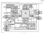
5-13. SCHEMATIC DIAGRAM - MAIN BOARD (1/4) (Suf...
Service Manual - Page 31

...12) - • See page 54 for IC Block Diagrams.
1
2
3
4
5
6
7
8
HCD-SH2000
9
10
11
12
13
14
15
A
MAIN BOARD (4/4)
29
R857
0
27
MAIN
26
6 BOARD
... BA4558F
BB1L BB2L OUTL AGCOUTL AGCC SWOUT CLK DATA AGCOUTR OUTR BB2R BB1R VOLINR TONEOUTR
15k
GAME IN-L
R739 27k
GAME
AUDIO IN
WHT
RED
L
R
C
D
MAIN
3
2 BOARD
1
(1/4)
2
(Page 28)
IC503
C694
R696
R698
R688...
Service Manual - Page 32

...
14
15
A B C D E F G H I
J
HCD-SH2000
DMB21 BOARD (Component side) NC
(CHASSIS)
MAIN
I BOARD
CN702 (Page 20) (...DEVICE, OPTICAL KHM-313CAB/C2RPA
MS-214 BOARD
DEVICE, OPTICAL KHM-313CAB/C2RP
32
32
Note 1: IC4605 on the DMB21 board is defective, exchange the entire MD (AU) ASSY. PRINTED WIRING BOARDS - Note 2: When the MS-214 board is damaged, exchange the entire mounted board. HCD-SH2000...
Service Manual - Page 37

...) (Suffix 11) (Page 22) (Suffix 12)
12 (12)
SWITCHING REGULATOR
37
37
HCD-SH2000
Ver. 1.1
15
DAMP BOARD (Component Side) - • See page 14 for Circuit Boards Location. • : Uses unleaded solder.
1
2
3
4
5
6
7
8
9
10
11
12
13
14
A B C D E F G H I
J
HCD-SH2000
DAMP BOARD (Component side)
LOW SPEAKER
(CHASSIS)
C1665
ET1400
L
R
,0PE'A1&E 8SE 4Ÿ
TB1400
Q1454...
Service Manual - Page 63
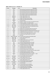
... terminal
I Current reference input terminal Fixed at "L" in this set
I Laser power monitor input from the system controller "L": reset
I IR control signal input terminal Not used
I/O Two-way audio serial data with the USB controller
- Ground terminal
O Reference voltage (+2V) output to the optical pick-up block
- HCD-SH2000
DMB21 BOARD (2/3) IC101 CXD9968R (LE...
Service Manual - Page 64

... AC coupled RF signal input from the optical pick-up block I Power monitor terminal I Audio data input from the motor driver
64 Not used - Not used - Not used
O ... terminal (+3.3V)
O Component video (Y) signal output terminal Not used O Component video (Pb/Cb) signal output terminal Not used O Component video (Pr/Cr) signal output terminal Not used - HCD-SH2000
Pin No. 69 to...
Service Manual - Page 70

...HCD-SH2000
Ver. 1.1 AUDIO-IN BUTTON
BUTTON LED
SECTION 7 ELECTRICAL PARTS LIST
Note: • Due to standardization, replacements in
the parts list may have some difference from the parts specified in the diagrams or the components...
• CAPACITORS uF: μF
• COILS uH: μH
The components identified by reference number, please include the board name.
• ...
Similar Questions

Hcd Sh2000 Sony
I have HCD SH 2000 it's has no audio out in any Chanel ( first it was on protection mode then now it...
I have HCD SH 2000 it's has no audio out in any Chanel ( first it was on protection mode then now it...
(Posted by Sehar517 1 year ago)

Speaker Wire Connector
looking for part number: 1-839-129-11 and 1-839-128-2
looking for part number: 1-839-129-11 and 1-839-128-2
(Posted by Crsj1981 2 years ago)

Sony Radio Circuit Hcd-sh2000
Good Dayi Am Interesting In Buying A Radio Circuit Hcd-sh2000 (only) And Whats The Price?
Good Dayi Am Interesting In Buying A Radio Circuit Hcd-sh2000 (only) And Whats The Price?
(Posted by diel060781 5 years ago)

Sony Mini Component Stereo System How Can I Fix Protect
(Posted by Siddka 10 years ago)

Sony Mhc Ec709ip How To Fix Protect
(Posted by clemmas 10 years ago)