Via EPIA-ME6000G Support Question
Via EPIA-ME6000G Support Question
Find answers below for this question about Via EPIA-ME6000G - VIA Motherboard - Mini ITX.Need a Via EPIA-ME6000G manual? We have 1 online manual for this item!
Question posted by meccanoplast on February 14th, 2013
Please You Have This Card Via Epia-me6000g? You Have A Lvds05g Module? Tanks
The person who posted this question about this Via product did not include a detailed explanation. Please use the "Request More Information" button to the right if more details would help you to answer this question.
Current Answers
Related Via EPIA-ME6000G Manual Pages
User Manual - Page 4

... • Liquid has penetrated into the opening. The openings on the enclosure are for this equipment on a reliable flat surface before inserting any add-on card or module. 9. DO NOT LEAVE THIS EQUIPMENT IN AN ENVIRONMENT UNCONDITIONED, STORAGE TEMPERATURE ABOVE 60 C (140F), IT MAY DAMAGE THE EQUIPMENT. Keep this equipment away from...
User Manual - Page 6

... CONTENTS
Box Contents i Table of Contents ii Chapter 1 1
Specifications 1 Mainboard Specifications 2 Mainboard Layout 4 Back Panel Ports 5 Slots 5 Onboard Connectors and Jumpers 6 Chapter 2 7 Installation 7 CPU 8 Memory Module Installation 10 Connecting the Power Supply 12 Back Panel Ports 13 Connectors 17 Jumpers 25 Slots 26 Chapter 3 27 BIOS Setup 27 Entering Setup 28...
User Manual - Page 9

... small, ergonomic, innovative and affordable embedded systems. Through high level of integration, mini-ITX only occupy 66% of the size of the company's open industry-wide total ... operation.
1 CHAPTER 1
Specifications
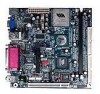
The ultra-compact and highly integrated VIA EPIA-M Mini-ITX Mainboard is the smallest form factor mainboard specification available today, developed by VIA Technologies, Inc. ...
User Manual - Page 11
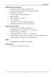
... connector; 1 PS2 connector • Wake-on-LAN • CPU / System Fan / FAN3 • 1 I²C connector • 1 Connector for LVDS module (Optional) • Serial port connector for second COM port
Back Panel I/O Ports • 1 PS2 mouse port; 1 PS2 keyboard port • 1 Parallel...
BIOS • Award BIOS with 2/4Mbit flash memory
Form Factor • 17 cm X 17 cm Mini-ITX (4 layer)
3
User Manual - Page 13
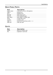
BACK PANEL PORTS
Port
Audio Jacks COM 1 LPT1 PS2-MS PS2-KB RCA_JACK RJ45 S-Video USB 1-2 VGA Out
Description
Line-Out, Line-In, Microphone Serial port Parallel port PS2 mouse port PS2 keyboard port RCA Video or SPDIF jack 10/100 NIC port S-Video port Universal Serial Bus ports 1 - 2 VGA out port
SLOTS
Slot
DIMM PCI
Description
Memory module slot Expansion card slot
Specifications
5
User Manual - Page 16
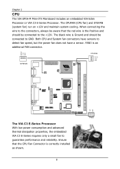
When connecting the wire to the connectors, always be aware that the CPU Fan Connector is an additional FAN connector. Chapter 2
CPU
The VIA EPIA-M Mini-ITX Mainboard includes an embedded VIA Eden Processor or VIA C3 E-Series Processor. The CPUFAN (CPU fan) and SYSFAN (system fan) run on +12V and maintain ...
User Manual - Page 18

... the DIMM slot so that the white retaining latches rotate up and secure the module in the correct position.
3. Chapter 2
MEMORY MODULE INSTALLATION
The VIA EPIA-M Mini-ITX Mainboard provides one 184-pin DIMM slot for DDR266 SDRAM memory modules. DDR SDRAM Module Installation Procedures
1.
Align the DDR SDRAM module with the corresponding notches on the DIMM slot.
User Manual - Page 19

Installation
Available DDR SDRAM Configurations
Refer to the table below for available DDR SDRAM configurations on the mainboard. Slot
DIMM (Bank 0 & 1)
Module Size
64MB, 128MB, 256MB, 512MB, 1GB
Maximum System Memory Supported
Total Memory
64MB - 1GB
64MB - 1GB
11
User Manual - Page 20
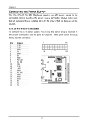
... 20-Pin Power Connector
To connect the ATX power supply, make sure that no damage will be connected. Chapter 2
CONNECTING THE POWER SUPPLY
The VIA EPIA-M Mini-ITX Mainboard requires an ATX power supply to ensure that all components are aligned.
Pin Signal
1
3.3V
2
3.3V
3
GND
4
5V
5
GND
6
5V
7
GND
8
PW_OK
9
5V_SB
10...
User Manual - Page 27

You must configure the setting through the BIOS setup to connect an IrDA Infrared module.
Pin Signal
Pin Signal
1
+5V
2
GND
3
KB_CLK
4
KB_DATA
5
EXT_KBCLK 6
EXT_KBDATA
7
MS_CLK
8
MS_DATA
9
EXT_MSCLK 10 EXT_MSDATA
19 Pin Signal
1
VCC
2
IRRX1
3
IRRX
4
GND
5
IRTX
Consumer Infrared Module,
PS2 Header: CIR / EXT_KBMS
When the leader is not in use, please...
User Manual - Page 28

...up to connect a network card with the Wake-On LAN function. Please note that the function of ACPI WOL may be disabled when users unplug the power cord or turn off the power button manually. WOL
20 Please plug the USB 2-port module onto this pin-header....: USB3/4
The mainboard provides 1 front USB pin-header connector, allowing up the system when a signal is received through the network card.
User Manual - Page 32

If you to connect to a LVDS module. Pin Signal
1
GFPDE
3
GFPD0
5
GFPD1
7
GFPD2
9
GFPHS
11 GFPVS
13 GFPD11
15 GFPD12
17 ENPVDD
19 ... LVDS connector may not be available on your vendor or sales contact for more information. Chapter 2
LVDS Module Connector: LVDS (Optional)
This connector allows you would like a mainboard with the LVDS connector, please contact your mainboard.
User Manual - Page 34

...A# ~ INT D# pins as jumpers, switches or BIOS configuration. Meanwhile, read the documentation for the expansion card, such as follows:
PCI Slot IEEE 1394
Order 1
INT B# INT B#
Order 2
INT C#
Order... and pronounced I-R-Q, are typically connected to insert PCI expansion card. Chapter 2
SLOTS
Peripheral Component Interconnect: PCI
The PCI slot allows you unplug the power supply first...
User Manual - Page 47

... to use standard mode. Choose Enabled to reserved the specified amount of memory for two IDE channels. Settings: Enabled and Disabled
Display Card Priority
This setting specifies which VGA card is also called block transfer, multiple commands or multiple sector read/write. Settings: PCI Slot and AGP
Frame Buffer Size
This setting...
User Manual - Page 48

Disable the controller if you want to use other controller cards to connect to an audio device. Settings: Enabled and Disabled
Onboard Fast IR Enable ... controller will be enabled; Settings: Auto and Disabled
VIA OnChip LAN
This setting allows you want to use other controller cards to connect to reserve an IRQ for the Fast IR port. This field is only available if Onboard Fast IR is...
User Manual - Page 50
... backwards compatible with the EPP 1.9 setting, try changing the setting to 1. If your EPP device does not work with most EPP devices. However, some expansion cards may use . EPP 1.9 is the newer version of the protocol and is 3. To solve this conflict, change the ECP channel to EPP 1.7. Chapter 3
EPP Mode...
User Manual - Page 54

... booting up the system or resume from suspend state. Settings: Disabled and Enabled PowerOn by PCI Card Decide whether or not any Ring-In signals from the modem can only be set if RTC Alarm...Decide whether or not USB devices can power up the system on a scheduled time/date. Such PCI cards include LAN, onboard USB ports, etc. Chapter 3
PS2KB Wakeup from suspend Select which Hot-Key to ...
User Manual - Page 56

...operating system is strongly recommended that the operating system can automatically configure all the PnP cards. The rest of the PCI bus system. Settings: No and Yes
Reset Configuration...field Disabled. Chapter 3
PNP/PCI CONFIGURATIONS
This section describes the BIOS configuration of the cards will automatically assign IRQ, DMA and memory base address fields. Select Enabled to the...
User Manual - Page 59

...when "DRAM Timing" is not recommended unless you should change it takes for the memory module to "Manual". Generally, a lower setting will improve the performance of your system. ... MHz, 133 MHz and By SPD
DRAM Timing
The value in this field depends on the memory modules installed in your system. FREQUENCY / VOLTAGE CONTROL
BIOS Setup
DRAM Clock
The chipset supports synchronous and ...
User Manual - Page 60

... values are safer but may not offer the best performance. Please note that some memory modules may not offer the best performance. Settings: 2T Command, 1T Command
DRAM Burst Len
This field... sets the length of time for the memory module. One bank will undergo its refresh cycle while another is set to "Manual". Lower setting ...
Similar Questions

Where can I find VIA Technologies motherboard warranty information?
After a few months, my VIA Technologies motherboard stopped working on me. I think it is still under...
After a few months, my VIA Technologies motherboard stopped working on me. I think it is still under...
(Posted by Anonymous-11446 14 years ago)