RSL12UL Wiring Diagram
Page 1
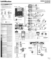
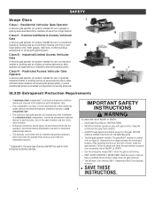
... Normal Operation No action required WIRING DIAGRAM Model RSL12UL COAXIAL CABLE ANTENNA Control Board DIAGNOSTICS J25 (see below allowable level. The operator will show the code sequence number followed by the code number: A SECOND LATER.... CODE COLOR KEY: LiftMaster System External Entrapment Protection Installed System Informational Inherent Entrapment Protection CODE MEANING SOLUTION Main...
... Normal Operation No action required WIRING DIAGRAM Model RSL12UL COAXIAL CABLE ANTENNA Control Board DIAGNOSTICS J25 (see below allowable level. The operator will show the code sequence number followed by the code number: A SECOND LATER.... CODE COLOR KEY: LiftMaster System External Entrapment Protection Installed System Informational Inherent Entrapment Protection CODE MEANING SOLUTION Main...

Owners Manual - English French
Page 1
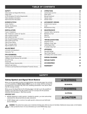
...in by texting the photo to locate a professional installing dealer in Class I and II vehicular slide gate applications. • Visit LiftMaster.com to 71403. RESIDENTIAL DC VEHICULAR SLIDE GATE OPERATOR INSTALLATION MANUAL Model RSL12UL LiftMaster 300 Windsor Drive Oak Brook, IL 60523 •...; THIS PRODUCT IS TO BE INSTALLED AND SERVICED BY A TRAINED GATE SYSTEMS TECHNICIAN ...
...in by texting the photo to locate a professional installing dealer in Class I and II vehicular slide gate applications. • Visit LiftMaster.com to 71403. RESIDENTIAL DC VEHICULAR SLIDE GATE OPERATOR INSTALLATION MANUAL Model RSL12UL LiftMaster 300 Windsor Drive Oak Brook, IL 60523 •...; THIS PRODUCT IS TO BE INSTALLED AND SERVICED BY A TRAINED GATE SYSTEMS TECHNICIAN ...
Owners Manual - English French
Page 2
... Step 5 Earth Ground Rod 15 Step 6 Power Wiring 15 Step 7 Dual gate setup 18 Step 8 Install the cover 20 ADJUSTMENT 21 Limit and Force Adjustment 21 Obstruction Test 22 PROGRAMMING 23 Remote Controls (Not Provided 23 LiftMaster Internet Gateway (not provided 24 Erase All Codes 24 Erase limits 24 Constant Pressure Override...
... Step 5 Earth Ground Rod 15 Step 6 Power Wiring 15 Step 7 Dual gate setup 18 Step 8 Install the cover 20 ADJUSTMENT 21 Limit and Force Adjustment 21 Obstruction Test 22 PROGRAMMING 23 Remote Controls (Not Provided 23 LiftMaster Internet Gateway (not provided 24 Erase All Codes 24 Erase limits 24 Constant Pressure Override...
Owners Manual - English French
Page 3
... A vehicular gate operator (or system) intended for both entrapment protection devices. It is unique. the same type of device shall NOT be installed at each direction; Keep the remote control away from the gate. l Use the emergency release ONLY when the gate is provided with a ...vehicular gate operator (or system) intended for vehicles ONLY. two in the open direction and two in each entrapment zone l Every installation is the responsibility of the installer to service the general public. Read the owner's manual. l KEEP GATES PROPERLY MAINTAINED. l The entrance is for use in ...
... A vehicular gate operator (or system) intended for both entrapment protection devices. It is unique. the same type of device shall NOT be installed at each direction; Keep the remote control away from the gate. l Use the emergency release ONLY when the gate is provided with a ...vehicular gate operator (or system) intended for vehicles ONLY. two in the open direction and two in each entrapment zone l Every installation is the responsibility of the installer to service the general public. Read the owner's manual. l KEEP GATES PROPERLY MAINTAINED. l The entrance is for use in ...
Owners Manual - English French
Page 4
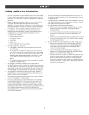
...users to operate the controls. Permanently mounted access controls intended for vehicles. Activation of a gate system. Gate systems design and installation must be visible by authorized personnel (e.g. Reference owner's manual regarding placement of non-contact sensor for each individual of the ...if provided separately) must be designed to reduce the risk of nuisance tripping, such as an edge sensor: a. SAFETY Safety Installation Information 1. Locate the gate such that enough clearance is still moving part of many component parts. Vehicular gate systems provide ...
...users to operate the controls. Permanently mounted access controls intended for vehicles. Activation of a gate system. Gate systems design and installation must be visible by authorized personnel (e.g. Reference owner's manual regarding placement of non-contact sensor for each individual of the ...if provided separately) must be designed to reduce the risk of nuisance tripping, such as an edge sensor: a. SAFETY Safety Installation Information 1. Locate the gate such that enough clearance is still moving part of many component parts. Vehicular gate systems provide ...
Owners Manual - English French
Page 5
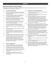
...a powered gate operator. Protrusions shall not be permitted on an automatically operated gate. The following . Gates shall be designed, constructed and installed such that the gate will enter a receiver guide, refer to prevent a 2 1⁄4 in the vicinity of the gate. Shall...Gates shall have smooth bottom edges, with ASTM F2200: Standard Specification for Exceptions. SAFETY Gate Construction Information Vehicular gates should be installed in accordance with vertical bottom edged protrusions not exceeding 0.50 inches (12.7 mm) when other fixed stationary objects greater than 16...
...a powered gate operator. Protrusions shall not be permitted on an automatically operated gate. The following . Gates shall be designed, constructed and installed such that the gate will enter a receiver guide, refer to prevent a 2 1⁄4 in the vicinity of the gate. Shall...Gates shall have smooth bottom edges, with ASTM F2200: Standard Specification for Exceptions. SAFETY Gate Construction Information Vehicular gates should be installed in accordance with vertical bottom edged protrusions not exceeding 0.50 inches (12.7 mm) when other fixed stationary objects greater than 16...
Owners Manual - English French
Page 8
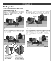
... determine the best device for your gate application. Gate must be UL approved for vehicles 14 feet (4.27 m) or longer. Before installing your Access Control Device(s) be sure to protect against any entrapment or safety conditions encountered in your site needs. 8 Before trenching, ...contact underground utility locating companies. Install a warning sign (two provided) on the inside and outside of operator (refer to stay open when vehicles are recommended. Conduit and...
... determine the best device for your gate application. Gate must be UL approved for vehicles 14 feet (4.27 m) or longer. Before installing your Access Control Device(s) be sure to protect against any entrapment or safety conditions encountered in your site needs. 8 Before trenching, ...contact underground utility locating companies. Install a warning sign (two provided) on the inside and outside of operator (refer to stay open when vehicles are recommended. Conduit and...
Owners Manual - English French
Page 9
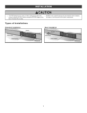
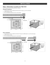
Types of Installations Standard Installation Rear Installation 9 INSTALLATION l To AVOID damaging gas, power or other underground utility lines, l ALWAYS wear protective gloves and eye protection when changing contact underground utility locating companies BEFORE digging more the battery or working around the battery compartment. than 18 inches (46 cm) deep.
Types of Installations Standard Installation Rear Installation 9 INSTALLATION l To AVOID damaging gas, power or other underground utility lines, l ALWAYS wear protective gloves and eye protection when changing contact underground utility locating companies BEFORE digging more the battery or working around the battery compartment. than 18 inches (46 cm) deep.
Owners Manual - English French
Page 10
The gate operator should be installed near the front roller of the gate in the OPEN position. Install the electrical conduit. 3. INSTALLATION Step 1 Determine Location for Operator Check the national and local building codes before installation. The gate operator should be installed near the back of the gate. Lay out the concrete pad. 2. Pour a concrete pad (reinforced concrete is recommended). 10 Lay out the concrete pad. 2. Standard Installation 1. Install the electrical conduit. 3. Pour a concrete pad (reinforced concrete is recommended). Rear Installation 1.
The gate operator should be installed near the front roller of the gate in the OPEN position. Install the electrical conduit. 3. INSTALLATION Step 1 Determine Location for Operator Check the national and local building codes before installation. The gate operator should be installed near the back of the gate. Lay out the concrete pad. 2. Pour a concrete pad (reinforced concrete is recommended). 10 Lay out the concrete pad. 2. Standard Installation 1. Install the electrical conduit. 3. Pour a concrete pad (reinforced concrete is recommended). Rear Installation 1.
Owners Manual - English French
Page 11
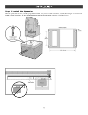
INSTALLATION Step 2 Install the Operator Attach the operator to the concrete pad with appropriate fasteners. The gate operator should be a minimum of the gate (in the OPEN position). The space between the gate and the output sprocket must be installed near the front roller of the gate or near the back of 4 inches (10.2 cm). 11
INSTALLATION Step 2 Install the Operator Attach the operator to the concrete pad with appropriate fasteners. The gate operator should be a minimum of the gate (in the OPEN position). The space between the gate and the output sprocket must be installed near the front roller of the gate or near the back of 4 inches (10.2 cm). 11

Owners Manual - English French
Page 12
...the idler pulley and parallel to the ground. Route the chain through the operator. 4. Weld the front bracket in the operator. 2. Rear Installation DO NOT run the operator until instructed. Move the back pulley to the brackets using the eye bolt hardware. NOTE: The chain should ...position. 3. Chain should have no more than 1 inch (2.5 cm) of sag for every 10 feet (3 m) of chain length. INSTALLATION Step 3 Attach the Chain Standard Installation DO NOT run the operator until instructed. 1. NOTE: The chain should not be level with the idler pulley and parallel to the ...
...the idler pulley and parallel to the ground. Route the chain through the operator. 4. Weld the front bracket in the operator. 2. Rear Installation DO NOT run the operator until instructed. Move the back pulley to the brackets using the eye bolt hardware. NOTE: The chain should ...position. 3. Chain should have no more than 1 inch (2.5 cm) of sag for every 10 feet (3 m) of chain length. INSTALLATION Step 3 Attach the Chain Standard Installation DO NOT run the operator until instructed. 1. NOTE: The chain should not be level with the idler pulley and parallel to the ...
Owners Manual - English French
Page 13
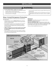
...from a moving gate and RIGID objects, such as posts, walls, pillars, columns or operator itself . Step 4 Install Entrapment Protection Entrapment protection MUST be installed according to the following UL 325 requirements: l Slide gate operators require a minimum of injury. Illustrations provided by DASMA... Guide 13 one in the open direction and one in BOTH the open and close direction. l LiftMaster monitored external entrapment protection devices MUST be installed to ensure that increases the risk of two external monitored entrapment protection devices to protect in the close...
...from a moving gate and RIGID objects, such as posts, walls, pillars, columns or operator itself . Step 4 Install Entrapment Protection Entrapment protection MUST be installed according to the following UL 325 requirements: l Slide gate operators require a minimum of injury. Illustrations provided by DASMA... Guide 13 one in the open direction and one in BOTH the open and close direction. l LiftMaster monitored external entrapment protection devices MUST be installed to ensure that increases the risk of two external monitored entrapment protection devices to protect in the close...
Owners Manual - English French
Page 14
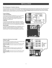
.... This input will reverse to the full open position, disengaging the Timer-to the expansion board. This input will open to the full open direction. INSTALLATION Wire Entrapment Protection Devices There are for monitored devices, which include pulsed photoelectric sensors, resistive edge sensors, and pulsed edge sensors. Additional entrapment protection devices...
.... This input will reverse to the full open position, disengaging the Timer-to the expansion board. This input will open to the full open direction. INSTALLATION Wire Entrapment Protection Devices There are for monitored devices, which include pulsed photoelectric sensors, resistive edge sensors, and pulsed edge sensors. Additional entrapment protection devices...

Owners Manual - English French
Page 15
... If you should be returned to lightning and surge damage. MUST NOT be performed until disconnecting the electrical power (AC l DO NOT install ANY wiring or attempt to Solar Panels section in the area near the operator l ALL electrical connections MUST be on a dedicated circuit ...better electrical, mechanical, and flammability ratings. Follow the directions according to each operator. NOTE: If the operator is charged in separate conduit. Install the earth ground rod within 3 feet (.9 m) of the remote controls will be reduced and the operator will have to be properly ...
... If you should be returned to lightning and surge damage. MUST NOT be performed until disconnecting the electrical power (AC l DO NOT install ANY wiring or attempt to Solar Panels section in the area near the operator l ALL electrical connections MUST be on a dedicated circuit ...better electrical, mechanical, and flammability ratings. Follow the directions according to each operator. NOTE: If the operator is charged in separate conduit. Install the earth ground rod within 3 feet (.9 m) of the remote controls will be reduced and the operator will have to be properly ...
Owners Manual - English French
Page 16
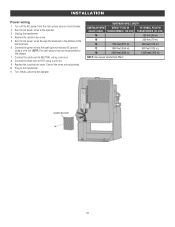
...: Use copper conductors ONLY. 16 Connect the green wire to the operator. Remove the junction box cover. 5. Plug in the bottom of the electrical box. 6. INSTALLATION Power wiring 1. Run the AC power wires to HOT using a wire nut. Connect the black wire to the operator. 3. Ensure the wires are not pinched...
...: Use copper conductors ONLY. 16 Connect the green wire to the operator. Remove the junction box cover. 5. Plug in the bottom of the electrical box. 6. INSTALLATION Power wiring 1. Run the AC power wires to HOT using a wire nut. Connect the black wire to the operator. 3. Ensure the wires are not pinched...
Owners Manual - English French
Page 17
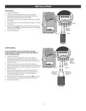
... wire harness kit to the positive (+) terminal on the control board by squeezing the plug and pulling it from the new J15 plug as shown. 4. INSTALLATION 7AH battery 1. Unplug the J15 plug labeled BATT on the battery as shown. This will power up the control board. Unplug the transformer. 2.
... wire harness kit to the positive (+) terminal on the control board by squeezing the plug and pulling it from the new J15 plug as shown. 4. INSTALLATION 7AH battery 1. Unplug the J15 plug labeled BATT on the battery as shown. This will power up the control board. Unplug the transformer. 2.
Owners Manual - English French
Page 18
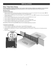
... accessories and board configurations are two options for dual gate communication: wired or wireless. Press and release the LEARN button again on the same operator. INSTALLATION Step 7 Dual Gate Setup There are set on the primary operator. 2. Follow the directions according to be programmed to the primary operator. Press and release...
... accessories and board configurations are two options for dual gate communication: wired or wireless. Press and release the LEARN button again on the same operator. INSTALLATION Step 7 Dual Gate Setup There are set on the primary operator. 2. Follow the directions according to be programmed to the primary operator. Press and release...
Owners Manual - English French
Page 19
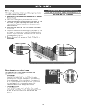
... one gate to cables. 1. Use PVC conduit to prevent damage to close from the shielded twisted pair cable to the secondary gate operator's control board. 5. INSTALLATION Wired setup Before digging, contact local underground utility locating companies.
... one gate to cables. 1. Use PVC conduit to prevent damage to close from the shielded twisted pair cable to the secondary gate operator's control board. 5. INSTALLATION Wired setup Before digging, contact local underground utility locating companies.
Owners Manual - English French
Page 20
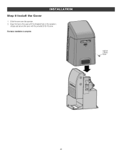
INSTALLATION Step 8 Install the Cover 1. Slide the cover over the operator. 2. The basic installation is complete. 20 Align the hole in the cover with the threaded hole in the operator's chassis and secure the cover with the provided 5/16-18 screw.
INSTALLATION Step 8 Install the Cover 1. Slide the cover over the operator. 2. The basic installation is complete. 20 Align the hole in the cover with the threaded hole in the operator's chassis and secure the cover with the provided 5/16-18 screw.
Owners Manual - English French
Page 21
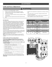
...operator will automatically exit limit setting mode. ADJUSTMENT Limit and Force Adjustment To reduce the risk of SEVERE INJURY or DEATH: l Without a properly installed safety reversal system, persons (particularly small children) could be attached to the operator before setting the limits and force. l NEVER use force adjustments... open and close . The electronic controls sense the amount of the MOVE GATE button to move gate. When limits are installed. Gate MUST reverse on gate will stop in the Appendix). For slide gate applications the open and close position.
...operator will automatically exit limit setting mode. ADJUSTMENT Limit and Force Adjustment To reduce the risk of SEVERE INJURY or DEATH: l Without a properly installed safety reversal system, persons (particularly small children) could be attached to the operator before setting the limits and force. l NEVER use force adjustments... open and close . The electronic controls sense the amount of the MOVE GATE button to move gate. When limits are installed. Gate MUST reverse on gate will stop in the Appendix). For slide gate applications the open and close position.


