
User Manual
Page 3
...Free-Standing 14 Using the Mounting Kit 15 Montagesatz Anweisungen 15 Placing Units On Top of Each Other 16 Supplying Power to the Switch 16 Checking for Correct Operation 17 Connecting a Network Device 17 Using SFP Transceivers 18 Approved SFP Transceivers 18 Inserting an SFP ... 24 Accessing the Interface Without Using Discovery 24 DHCP Assigned IP Address 24 Manually Assigned (Static) IP Address 25 4 CONFIGURING THE SWITCH Configuration Overview 27 Viewing Status Information 27 Changing the Admin Password 28 Modifying the IP Address Settings 29 Automatic IP Configuration 29 Setting ...
...Free-Standing 14 Using the Mounting Kit 15 Montagesatz Anweisungen 15 Placing Units On Top of Each Other 16 Supplying Power to the Switch 16 Checking for Correct Operation 17 Connecting a Network Device 17 Using SFP Transceivers 18 Approved SFP Transceivers 18 Inserting an SFP ... 24 Accessing the Interface Without Using Discovery 24 DHCP Assigned IP Address 24 Manually Assigned (Static) IP Address 25 4 CONFIGURING THE SWITCH Configuration Overview 27 Viewing Status Information 27 Changing the Admin Password 28 Modifying the IP Address Settings 29 Automatic IP Configuration 29 Setting ...
User Manual
Page 4
... Traffic Priority 40 IP Phone Prioritization 40 List of Detected Phones 41 Upgrading the Firmware 41 Downloading Firmware Updates 41 Installing the Firmware on the Switch 42 5 TROUBLESHOOTING Resetting to Factory Defaults 43 Forgotten Password 44 Forgotten Static IP Address 44 Solving LED Issues 44 Solving Corrupted Firmware 45 If the...
... Traffic Priority 40 IP Phone Prioritization 40 List of Detected Phones 41 Upgrading the Firmware 41 Downloading Firmware Updates 41 Installing the Firmware on the Switch 42 5 TROUBLESHOOTING Resetting to Factory Defaults 43 Forgotten Password 44 Forgotten Static IP Address 44 Solving LED Issues 44 Solving Corrupted Firmware 45 If the...

User Manual
Page 6
... very important to us : ■ Document title ■ Document part number (on the title page) ■ Page number (if appropriate) Example: ■ 3Com Baseline Switch 2226 Plus User Guide ■ Part number: DUA16475B-SAAA01 ■ Page 25 Please note that helps you . Questions related to technical support or sales should... instance to you perform tasks using the Web interface. ■ Release Notes - 6 ABOUT THIS GUIDE Related Documentation In addition to this guide, each 3Com Baseline Switch 2226 Plus documentation set includes the following information when contacting us .
... very important to us : ■ Document title ■ Document part number (on the title page) ■ Page number (if appropriate) Example: ■ 3Com Baseline Switch 2226 Plus User Guide ■ Part number: DUA16475B-SAAA01 ■ Page 25 Please note that helps you . Questions related to technical support or sales should... instance to you perform tasks using the Web interface. ■ Release Notes - 6 ABOUT THIS GUIDE Related Documentation In addition to this guide, each 3Com Baseline Switch 2226 Plus documentation set includes the following information when contacting us .

User Manual
Page 7
...Gigabit links, but do not need sophisticated management capabilities. Autosensing of the Baseline Switch 2226 Plus The 3Com Baseline Switch 2226 Plus is shipped ready for easy, flexible connection to another switch port, server, or workstation without additional configuration. Any port can autosense both ... Mbps Ports Each 10/100 Mbps port automatically determines the speed and duplex mode of the 3Com® Baseline Switch 2226 Plus. 1 INTRODUCING THE BASELINE SWITCH This chapter provides an overview of the features and capabilities of the connected equipment and provides a ...
...Gigabit links, but do not need sophisticated management capabilities. Autosensing of the Baseline Switch 2226 Plus The 3Com Baseline Switch 2226 Plus is shipped ready for easy, flexible connection to another switch port, server, or workstation without additional configuration. Any port can autosense both ... Mbps Ports Each 10/100 Mbps port automatically determines the speed and duplex mode of the 3Com® Baseline Switch 2226 Plus. 1 INTRODUCING THE BASELINE SWITCH This chapter provides an overview of the features and capabilities of the connected equipment and provides a ...

User Manual
Page 8
...connected to ensure that traffic. Traffic prioritization uses multiple traffic queues that are shown in Table 3. 8 CHAPTER 1: INTRODUCING THE BASELINE SWITCH SFP Ports The two SFP ports support fiber Gigabit Ethernet short-wave (SX) and long-wave (LX) SFP transceivers in any ...offers you use a single wall jack for example, during its initialization, do not connect any of which relates to provide connectivity between the Switch and a 1000 Mbps core network. It differentiates traffic into classes and prioritizes those classes automatically. Table 3 Priority Levels for example, a...
...connected to ensure that traffic. Traffic prioritization uses multiple traffic queues that are shown in Table 3. 8 CHAPTER 1: INTRODUCING THE BASELINE SWITCH SFP Ports The two SFP ports support fiber Gigabit Ethernet short-wave (SX) and long-wave (LX) SFP transceivers in any ...offers you use a single wall jack for example, during its initialization, do not connect any of which relates to provide connectivity between the Switch and a 1000 Mbps core network. It differentiates traffic into classes and prioritizes those classes automatically. Table 3 Priority Levels for example, a...

User Manual
Page 9
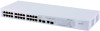
...(interactive voice), less than 10 milliseconds latency and jitter 7 Network control reserved traffic The traffic prioritization feature supported by the Switch is compatible with shielded or unshielded jacks can be used as standard traditional telephone sockets, or to connect the unit to a... traditional PBX or public telephone network. Figure 1 Front and Rear Panels 1 2 3 3C16475B 8 4 9 56 7 Front Panel The front panel of the Switch contains a series of indicator lights (LEDs) that help describe the state of various networking and connection operations. (1) ...
...(interactive voice), less than 10 milliseconds latency and jitter 7 Network control reserved traffic The traffic prioritization feature supported by the Switch is compatible with shielded or unshielded jacks can be used as standard traditional telephone sockets, or to connect the unit to a... traditional PBX or public telephone network. Figure 1 Front and Rear Panels 1 2 3 3C16475B 8 4 9 56 7 Front Panel The front panel of the Switch contains a series of indicator lights (LEDs) that help describe the state of various networking and connection operations. (1) ...

User Manual
Page 10
...; possibile collegare cavi dati schermati o non schermati con connettori schermati o non schermati. If the connected device does not support autonegotiation, the Switch will operate in half-duplex mode (even if the attached device is inserted in full-duplex mode). Nur RJ-45-Datenanscluße, Telefonnetzsysteme... o teléfonos de red local a estas tomas. In such a configuration, you may notice some degradation of network performance. 3Com recommends that you use devices that are capable of autonegotiation (and that you ensure that autonegotiation is enabled, if it is operating at...
...; possibile collegare cavi dati schermati o non schermati con connettori schermati o non schermati. If the connected device does not support autonegotiation, the Switch will operate in half-duplex mode (even if the attached device is inserted in full-duplex mode). Nur RJ-45-Datenanscluße, Telefonnetzsysteme... o teléfonos de red local a estas tomas. In such a configuration, you may notice some degradation of network performance. 3Com recommends that you use devices that are capable of autonegotiation (and that you ensure that autonegotiation is enabled, if it is operating at...

User Manual
Page 11
... failed. rectly ■ If the unit still does not operate, contact your 3Com network supplier for use straight-through or crossover cables for all network connections to workstations or servers, or to other switches or hubs. Status Meaning Flashing Yellow Packets are being received or transmitted on the.... Status Green Off Flashing Green Yellow Meaning The unit is in a slot and is active, the associated RJ-45 port of the Switch. Contact your 3Com network supplier ■ Power-on self-test is powered on and ready for further advice. (4) 10/100/1000BASE-T/SFP Ports Ports 25...
... failed. rectly ■ If the unit still does not operate, contact your 3Com network supplier for use straight-through or crossover cables for all network connections to workstations or servers, or to other switches or hubs. Status Meaning Flashing Yellow Packets are being received or transmitted on the.... Status Green Off Flashing Green Yellow Meaning The unit is in a slot and is active, the associated RJ-45 port of the Switch. Contact your 3Com network supplier ■ Power-on self-test is powered on and ready for further advice. (4) 10/100/1000BASE-T/SFP Ports Ports 25...
User Manual
Page 12
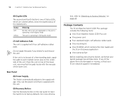
... the unit. If the unit is supplied with the recesses of the lower unit. Package Contents The 3Com Baseline Switch 2226 Plus package includes the following items: ■ One 3Com Baseline Switch 2226 Plus unit ■ One power cord ■ Four standard height, self-adhesive rubber pads &#...page 43. 12 CHAPTER 1: INTRODUCING THE BASELINE SWITCH (6) Duplex LEDs The second and fourth (bottom) row of Status LEDs, which contains this User Guide and the 3Com Discovery application ■ One warranty flyer Before installing and using the Switch, verify that the pads locate with four ...
... the unit. If the unit is supplied with the recesses of the lower unit. Package Contents The 3Com Baseline Switch 2226 Plus package includes the following items: ■ One 3Com Baseline Switch 2226 Plus unit ■ One power cord ■ Four standard height, self-adhesive rubber pads &#...page 43. 12 CHAPTER 1: INTRODUCING THE BASELINE SWITCH (6) Duplex LEDs The second and fourth (bottom) row of Status LEDs, which contains this User Guide and the 3Com Discovery application ■ One warranty flyer Before installing and using the Switch, verify that the pads locate with four ...

User Manual
Page 13
...233;curité qui se trouvent dans l'Appendice B (Appendix B) de ce guide. Bevor Sie Komponenten aus dem Switch entfernen oder dem Switch hinzufuegen oder Instandhaltungsarbe- Antes de instalar o extraer cualquier componente del product o de realizar tareas de mantenimiento, debe leer ... riportate nell'Appendice B (Appendix B) della presente guida per l'utente. ADVERTENCIA: Información de Seguridad. When deciding where to the Switch ■ Connecting a Network Device ■ Connecting a Network Device ■ Performing Spot Checks Before You Begin WARNING: Safety Information. ...
...233;curité qui se trouvent dans l'Appendice B (Appendix B) de ce guide. Bevor Sie Komponenten aus dem Switch entfernen oder dem Switch hinzufuegen oder Instandhaltungsarbe- Antes de instalar o extraer cualquier componente del product o de realizar tareas de mantenimiento, debe leer ... riportate nell'Appendice B (Appendix B) della presente guida per l'utente. ADVERTENCIA: Información de Seguridad. When deciding where to the Switch ■ Connecting a Network Device ■ Connecting a Network Device ■ Performing Spot Checks Before You Begin WARNING: Safety Information. ...

User Manual
Page 14
... kann. ■ Weder Wasser noch Feuchtigkeit in das Gehause eindringen kann. ■ Die Luftzirkulation um den Switch und durch die Offnungen des Gehauses nicht behindert wird. 3Com empfiehlt das Sie 25mm (1 Inch) Zwischenraum sicherstellen. ■ Die Luft so frei wie moglich von Staub ...ist. ■ Es unwahrscheinlich ist das die Betriebstemperatur uberschritten wird. 3Com empfiehlt das Sie den Switch in der nahe von elektrischen Storquellen befinden. If one is recommended that you provide a minimum of electrical noise. clearance). &#...
... kann. ■ Weder Wasser noch Feuchtigkeit in das Gehause eindringen kann. ■ Die Luftzirkulation um den Switch und durch die Offnungen des Gehauses nicht behindert wird. 3Com empfiehlt das Sie 25mm (1 Inch) Zwischenraum sicherstellen. ■ Die Luft so frei wie moglich von Staub ...ist. ■ Es unwahrscheinlich ist das die Betriebstemperatur uberschritten wird. 3Com empfiehlt das Sie den Switch in der nahe von elektrischen Storquellen befinden. If one is recommended that you provide a minimum of electrical noise. clearance). &#...

User Manual
Page 15
... (Zoll) Baugruppenträger. Bei der Montage der Baugruppe beachten Sie die Anweisungen aus "Aufstellen des Switch". When mounting the unit, take note of the guidelines given in "Positioning the Switch" on one side of the unit. 3 Insert the two screws supplied in the mounting kit and ...fully tighten with suitable screws (not provided). Figure 2 Inserting the Screws 4 Repeat the two previous steps for rack mounting the unit. Der Switch ist eine Baueinheit hoch und passt in einen Baugruppenträger benutzt. These are not obstructed. 6 Reconnect the network cables. Rack-Mounting or ...
... (Zoll) Baugruppenträger. Bei der Montage der Baugruppe beachten Sie die Anweisungen aus "Aufstellen des Switch". When mounting the unit, take note of the guidelines given in "Positioning the Switch" on one side of the unit. 3 Insert the two screws supplied in the mounting kit and ...fully tighten with suitable screws (not provided). Figure 2 Inserting the Screws 4 Repeat the two previous steps for rack mounting the unit. Der Switch ist eine Baueinheit hoch und passt in einen Baugruppenträger benutzt. These are not obstructed. 6 Reconnect the network cables. Rack-Mounting or ...

User Manual
Page 16
...grounded. Before powering on top of the lower unit. Apply the pads to avoid damage from sags and surges to avoid unforeseen network outages. 3Com recommends that the pads of serious failures and downtime in the marked area at the top. Installing proper grounding helps to the underside of ...each other , you are free-standing, up with the recesses of the other end of each Switch, sticking one on the Switch, verify that the power input to your network. If you must be placed one in your system is clean and free from ...
...grounded. Before powering on top of the lower unit. Apply the pads to avoid damage from sags and surges to avoid unforeseen network outages. 3Com recommends that the pads of serious failures and downtime in the marked area at the top. Installing proper grounding helps to the underside of ...each other , you are free-standing, up with the recesses of the other end of each Switch, sticking one on the Switch, verify that the power input to your network. If you must be placed one in your system is clean and free from ...
User Manual
Page 17
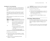
...POST is in fail-safe mode. If these do not resolve the issue: ■ Check the 3Com Knowledgebase for the Power LED after POST. For optimal connections, ensure that POST failed and the Switch has entered fail-safe mode. During POST, the Power LED on again. Off The unit is not... is not longer than 100 m (328 ft). You will need to its factory defaults erases all your 3Com network supplier for assistance. If the Power LED turns yellow after you power on the Switch, it automatically performs a power-on self-test or loopback test failed. Table 4 summarizes the possible colors ...
...POST is in fail-safe mode. If these do not resolve the issue: ■ Check the 3Com Knowledgebase for the Power LED after POST. For optimal connections, ensure that POST failed and the Switch has entered fail-safe mode. During POST, the Power LED on again. Off The unit is not... is not longer than 100 m (328 ft). You will need to its factory defaults erases all your 3Com network supplier for assistance. If the Power LED turns yellow after you power on the Switch, it automatically performs a power-on self-test or loopback test failed. Table 4 summarizes the possible colors ...

User Manual
Page 18
... them from and insert them into your Internet browser: http://www.3com.com 3Com recommends using 3Com SFPs on the Switch. To insert an SFP transceiver: 1 Hold the transceiver so that is faulty, it . For 1000BASE-T operation, 3Com recommends using a conditioned launch cable. Inserting an SFP Transceiver To...fiber-optic cable. ■ 1000BASE-LX SFP transceiver - Approved SFP Transceivers The following list of approved SFP transceivers for the Switch on the 3Com Corporation World Wide Web site, enter this URL into any SFP port without having to insert and remove an SFP transceiver ...
... them from and insert them into your Internet browser: http://www.3com.com 3Com recommends using 3Com SFPs on the Switch. To insert an SFP transceiver: 1 Hold the transceiver so that is faulty, it . For 1000BASE-T operation, 3Com recommends using a conditioned launch cable. Inserting an SFP Transceiver To...fiber-optic cable. ■ 1000BASE-LX SFP transceiver - Approved SFP Transceivers The following list of approved SFP transceivers for the Switch on the 3Com Corporation World Wide Web site, enter this URL into any SFP port without having to insert and remove an SFP transceiver ...

User Manual
Page 19
...SFP transceivers are keyed and can be attended to a device fitted with an appropriate Gigabit Ethernet connection. 7 Check the Module Active LEDs on users. 3Com recommends periodically checking the items listed in Table 5. Ensure the wire release lever is operating correctly. Attach a male duplex LC connector on the network ...cable into the SFP slot until it is pointing toward you. 3 Pull the wire release lever toward you an early warning of the Switch to ensure that it is closed (in Figure 4. Removing an SFP Transceiver Removing an SFP transceiver does not require powering off the...
...SFP transceivers are keyed and can be attended to a device fitted with an appropriate Gigabit Ethernet connection. 7 Check the Module Active LEDs on users. 3Com recommends periodically checking the items listed in Table 5. Ensure the wire release lever is operating correctly. Attach a male duplex LC connector on the network ...cable into the SFP slot until it is pointing toward you. 3 Pull the wire release lever toward you an early warning of the Switch to ensure that it is closed (in Figure 4. Removing an SFP Transceiver Removing an SFP transceiver does not require powering off the...

User Manual
Page 20
If you experience any problems operating the Switch, refer to the unit. The fan is operating by listening to "Troubleshooting" starting on the right side of the unit (when viewed from the front). 20 CHAPTER 2: INSTALLING THE SWITCH Table 5 Items to Check Item Verify That Cabling All external cabling connections are secure and that no cables are pulled taut Cooling fan Where possible, check that the cooling fan is fitted on page 43.
If you experience any problems operating the Switch, refer to the unit. The fan is operating by listening to "Troubleshooting" starting on the right side of the unit (when viewed from the front). 20 CHAPTER 2: INSTALLING THE SWITCH Table 5 Items to Check Item Verify That Cabling All external cabling connections are secure and that no cables are pulled taut Cooling fan Where possible, check that the cooling fan is fitted on page 43.

User Manual
Page 21
... should start automatically, go to access the Web interface and configure the Switch. To use to set the admin password, change the IP address that has a Web browser Running the Discovery Application The 3Com Baseline Switch 2226 Plus CD-ROM contains, among others, the Discovery application. The ...following : ■ The Discovery application, which is included on 3Com Baseline Switch 2226 Plus CD-ROM that is supplied with your Switch ■ A computer that is connected to the Switch and that is connected to the Switch, insert the CD-ROM into its advanced settings. If it does...
... should start automatically, go to access the Web interface and configure the Switch. To use to set the admin password, change the IP address that has a Web browser Running the Discovery Application The 3Com Baseline Switch 2226 Plus CD-ROM contains, among others, the Discovery application. The ...following : ■ The Discovery application, which is included on 3Com Baseline Switch 2226 Plus CD-ROM that is supplied with your Switch ■ A computer that is connected to the Switch and that is connected to the Switch, insert the CD-ROM into its advanced settings. If it does...

User Manual
Page 22
.... 3 On the Discovered Devices screen, click Baseline Switch 2226 Plus, and then click Next. When detection is the logon screen. The Completing the 3Com Discovery Application screen appears. 4 Click Finish. Discovery searches the network for 3Com devices. On this screen, you need to enter ...the administration user name and password to gain access to the Switch, and then click Next. The Web...
.... 3 On the Discovered Devices screen, click Baseline Switch 2226 Plus, and then click Next. When detection is the logon screen. The Completing the 3Com Discovery Application screen appears. 4 Click Finish. Discovery searches the network for 3Com devices. On this screen, you need to enter ...the administration user name and password to gain access to the Switch, and then click Next. The Web...

User Manual
Page 23
... 7 Logon Screen Navigating the Web Interface 23 related screen appears in the main part of the Switch Port Configuration Allows you to configure the Switch's port settings Figure 8 Switch Screen Layout To log on to configure the IP address settings of the interface. Table 6 Available... Menu Items Menu Item Description Status Provides a summary of the Switch's basic settings and versions of current components Password Allows you to change the administrator password IP Settings Allows you to the Web ...
... 7 Logon Screen Navigating the Web Interface 23 related screen appears in the main part of the Switch Port Configuration Allows you to configure the Switch's port settings Figure 8 Switch Screen Layout To log on to configure the IP address settings of the interface. Table 6 Available... Menu Items Menu Item Description Status Provides a summary of the Switch's basic settings and versions of current components Password Allows you to change the administrator password IP Settings Allows you to the Web ...