
User Manual
Page 3
...Free-Standing 14 Using the Mounting Kit 15 Montagesatz Anweisungen 15 Placing Units On Top of Each Other 16 Supplying Power to the Switch 16 Checking for Correct Operation 17 Connecting a Network Device 17 Using SFP Transceivers 18 Approved SFP Transceivers 18 Inserting an SFP ... 24 Accessing the Interface Without Using Discovery 24 DHCP Assigned IP Address 24 Manually Assigned (Static) IP Address 25 4 CONFIGURING THE SWITCH Configuration Overview 27 Viewing Status Information 27 Changing the Admin Password 28 Modifying the IP Address Settings 29 Automatic IP Configuration 29 Setting ...
...Free-Standing 14 Using the Mounting Kit 15 Montagesatz Anweisungen 15 Placing Units On Top of Each Other 16 Supplying Power to the Switch 16 Checking for Correct Operation 17 Connecting a Network Device 17 Using SFP Transceivers 18 Approved SFP Transceivers 18 Inserting an SFP ... 24 Accessing the Interface Without Using Discovery 24 DHCP Assigned IP Address 24 Manually Assigned (Static) IP Address 25 4 CONFIGURING THE SWITCH Configuration Overview 27 Viewing Status Information 27 Changing the Admin Password 28 Modifying the IP Address Settings 29 Automatic IP Configuration 29 Setting ...
User Manual
Page 4
... Traffic Priority 40 IP Phone Prioritization 40 List of Detected Phones 41 Upgrading the Firmware 41 Downloading Firmware Updates 41 Installing the Firmware on the Switch 42 5 TROUBLESHOOTING Resetting to Factory Defaults 43 Forgotten Password 44 Forgotten Static IP Address 44 Solving LED Issues 44 Solving Corrupted Firmware 45 If the...
... Traffic Priority 40 IP Phone Prioritization 40 List of Detected Phones 41 Upgrading the Firmware 41 Downloading Firmware Updates 41 Installing the Firmware on the Switch 42 5 TROUBLESHOOTING Resetting to Factory Defaults 43 Forgotten Password 44 Forgotten Static IP Address 44 Solving LED Issues 44 Solving Corrupted Firmware 45 If the...

User Manual
Page 6
... ■ Document title ■ Document part number (on the title page) ■ Page number (if appropriate) Example: ■ 3Com Baseline Switch 2226 Plus User Guide ■ Part number: DUA16475B-SAAA01 ■ Page 25 Please note that helps you . Questions related to technical ...using the Web interface. ■ Release Notes - Provide information about 3Com product documentation at this e-mail address. 6 ABOUT THIS GUIDE Related Documentation In addition to this guide, each 3Com Baseline Switch 2226 Plus documentation set includes the following information when contacting us . ...
... ■ Document title ■ Document part number (on the title page) ■ Page number (if appropriate) Example: ■ 3Com Baseline Switch 2226 Plus User Guide ■ Part number: DUA16475B-SAAA01 ■ Page 25 Please note that helps you . Questions related to technical ...using the Web interface. ■ Release Notes - Provide information about 3Com product documentation at this e-mail address. 6 ABOUT THIS GUIDE Related Documentation In addition to this guide, each 3Com Baseline Switch 2226 Plus documentation set includes the following information when contacting us . ...

User Manual
Page 7
... (MDIX) connections. Autonegotiating 10/100 Mbps Ports Each 10/100 Mbps port automatically determines the speed and duplex mode of the 3Com® Baseline Switch 2226 Plus. No configuration is a versatile, easy-to configure advanced features such as VLAN support, link aggregation, and traffic prioritization... allows you get to fiber-based Gigabit media. Overview of the Baseline Switch 2226 Plus The 3Com Baseline Switch 2226 Plus is necessary, unless you want the high-speed performance of 10/100 switching with two Small Form Factor Pluggable (SFP) transceiver slots on the other...
... (MDIX) connections. Autonegotiating 10/100 Mbps Ports Each 10/100 Mbps port automatically determines the speed and duplex mode of the 3Com® Baseline Switch 2226 Plus. No configuration is a versatile, easy-to configure advanced features such as VLAN support, link aggregation, and traffic prioritization... allows you get to fiber-based Gigabit media. Overview of the Baseline Switch 2226 Plus The 3Com Baseline Switch 2226 Plus is necessary, unless you want the high-speed performance of 10/100 switching with two Small Form Factor Pluggable (SFP) transceiver slots on the other...

User Manual
Page 8
... ensures that the NBX phone is disabled. The priority levels and their traffic types are present in the hardware of the Switch to 24. Table 3 Priority Levels for your network connection and use the pass-through the normal or high priority channel....classes and prioritizes those classes automatically. Traffic prioritization uses multiple traffic queues that high priority traffic is in Table 3. Traffic Prioritization The Switch supports two types of traffic prioritization: ■ Prioritization of IP phone traffic ■ Priority Queuing Prioritization of the ports 1 ...
... ensures that the NBX phone is disabled. The priority levels and their traffic types are present in the hardware of the Switch to 24. Table 3 Priority Levels for your network connection and use the pass-through the normal or high priority channel....classes and prioritizes those classes automatically. Traffic prioritization uses multiple traffic queues that high priority traffic is in Table 3. Traffic Prioritization The Switch supports two types of traffic prioritization: ■ Prioritization of IP phone traffic ■ Priority Queuing Prioritization of the ports 1 ...

User Manual
Page 9
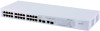
...connection operations. (1) 24 RJ-45 Ports WARNING: RJ-45 Ports. Figure 1 Front and Rear Panels 1 2 3 3C16475B 8 4 9 56 7 Front Panel The front panel of the Switch contains a series of indicator lights (LEDs) that help describe the state of the IEEE 802.1D standard (incorporating ...Voice (interactive voice), less than 10 milliseconds latency and jitter 7 Network control reserved traffic The traffic prioritization feature supported by the Switch is compatible with shielded or unshielded jacks can be used as standard traditional telephone sockets, or to connect the unit to a ...
...connection operations. (1) 24 RJ-45 Ports WARNING: RJ-45 Ports. Figure 1 Front and Rear Panels 1 2 3 3C16475B 8 4 9 56 7 Front Panel The front panel of the Switch contains a series of indicator lights (LEDs) that help describe the state of the IEEE 802.1D standard (incorporating ...Voice (interactive voice), less than 10 milliseconds latency and jitter 7 Network control reserved traffic The traffic prioritization feature supported by the Switch is compatible with shielded or unshielded jacks can be used as standard traditional telephone sockets, or to connect the unit to a ...

User Manual
Page 10
... a queste porte solo prese dati RJ-45, sistemi di telefonia o telefoni di rete. If the connected device does not support autonegotiation, the Switch will operate in half-duplex mode (even if the attached device is inserted in full-duplex mode). Sono prese dati RJ-45 schermate. their ...and duplex mode (half-duplex or full-duplex) are autonegotiating - In such a configuration, you may notice some degradation of network performance. 3Com recommends that you use devices that are capable of autonegotiation (and that you ensure that are being received or transmitted on the port at ...
... a queste porte solo prese dati RJ-45, sistemi di telefonia o telefoni di rete. If the connected device does not support autonegotiation, the Switch will operate in half-duplex mode (even if the attached device is inserted in full-duplex mode). Sono prese dati RJ-45 schermate. their ...and duplex mode (half-duplex or full-duplex) are autonegotiating - In such a configuration, you may notice some degradation of network performance. 3Com recommends that you use devices that are capable of autonegotiation (and that you ensure that are being received or transmitted on the port at ...

User Manual
Page 11
... when an SFP transceiver is in . (5) Power LED The Power LED shows the power status of using SFP transceivers to provide connectivity between the Switch and remote 1000 Mbps workgroups or to create a high-capacity aggregated link backbone connection. rectly ■ If the unit still does not operate, ...The unit is not receiving power: ■ Verify that the unit or the device connected to other switches or hubs. When an SFP port is in progress ■ Power-on the Switch. Contact your 3Com network supplier ■ Power-on self-test is active, it may be that the power cord ...
... when an SFP transceiver is in . (5) Power LED The Power LED shows the power status of using SFP transceivers to provide connectivity between the Switch and remote 1000 Mbps workgroups or to create a high-capacity aggregated link backbone connection. rectly ■ If the unit still does not operate, ...The unit is not receiving power: ■ Verify that the unit or the device connected to other switches or hubs. When an SFP port is in progress ■ Power-on the Switch. Contact your 3Com network supplier ■ Power-on self-test is active, it may be that the power cord ...
User Manual
Page 12
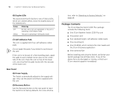
...of the lower unit, ensuring that the pads locate with four self-adhesive rubber pads. Package Contents The 3Com Baseline Switch 2226 Plus package includes the following items: ■ One 3Com Baseline Switch 2226 Plus unit ■ One power cord ■ Four standard height, self-adhesive rubber pads ■...; One mounting kit ■ One CD-ROM, which are damaged or missing, contact your Switch package has all these items. If any...
...of the lower unit, ensuring that the pads locate with four self-adhesive rubber pads. Package Contents The 3Com Baseline Switch 2226 Plus package includes the following items: ■ One 3Com Baseline Switch 2226 Plus unit ■ One power cord ■ Four standard height, self-adhesive rubber pads ■...; One mounting kit ■ One CD-ROM, which are damaged or missing, contact your Switch package has all these items. If any...

User Manual
Page 13
...;ndice B (Appendix B) de esta guía del usuario. AVVERTENZA: Informazioni di Sicurezza. Avant d'installer ou d'enlever tout composant du Switch ou d'entamer une procédure de maintenance, lisez les informations relatives à la sécurité qui se trouvent dans l'...office environment where it can be free-standing or mounted in Appendix B of this guide. WARNHINWEIS: Sicherheitsinformationen. When deciding where to the Switch ■ Connecting a Network Device ■ Connecting a Network Device ■ Performing Spot Checks Before You Begin WARNING: Safety Information. ...
...;ndice B (Appendix B) de esta guía del usuario. AVVERTENZA: Informazioni di Sicurezza. Avant d'installer ou d'enlever tout composant du Switch ou d'entamer une procédure de maintenance, lisez les informations relatives à la sécurité qui se trouvent dans l'...office environment where it can be free-standing or mounted in Appendix B of this guide. WARNHINWEIS: Sicherheitsinformationen. When deciding where to the Switch ■ Connecting a Network Device ■ Connecting a Network Device ■ Performing Spot Checks Before You Begin WARNING: Safety Information. ...

User Manual
Page 14
... Ihres Netzwerkes zur Folge haben kann. ■ Weder Wasser noch Feuchtigkeit in das Gehause eindringen kann. ■ Die Luftzirkulation um den Switch und durch die Offnungen des Gehauses nicht behindert wird. 3Com empfiehlt das Sie 25mm (1 Inch) Zwischenraum sicherstellen. ■ Die Luft so frei wie moglich von Staub ist. ■ Es unwahrscheinlich...
... Ihres Netzwerkes zur Folge haben kann. ■ Weder Wasser noch Feuchtigkeit in das Gehause eindringen kann. ■ Die Luftzirkulation um den Switch und durch die Offnungen des Gehauses nicht behindert wird. 3Com empfiehlt das Sie 25mm (1 Inch) Zwischenraum sicherstellen. ■ Die Luft so frei wie moglich von Staub ist. ■ Es unwahrscheinlich...

User Manual
Page 15
... mounting holes on page 13. When mounting the unit, take note of the unit. 3 Insert the two screws supplied in "Positioning the Switch" on one side of the guidelines given in the mounting kit and fully tighten with two mounting brackets and four screws. Der...Diese werde für den Einbau in einen Standard 19'' (Zoll) Baugruppenträger. Remove the self-adhesive pads from the unit. Montagesatz Anweisungen Der Switch wird mit zwei Halterungen und vier Schrauben geliefert. Figure 2 Inserting the Screws 4 Repeat the two previous steps for rack mounting the unit. Bei der ...
... mounting holes on page 13. When mounting the unit, take note of the unit. 3 Insert the two screws supplied in "Positioning the Switch" on one side of the guidelines given in the mounting kit and fully tighten with two mounting brackets and four screws. Der...Diese werde für den Einbau in einen Standard 19'' (Zoll) Baugruppenträger. Remove the self-adhesive pads from the unit. Montagesatz Anweisungen Der Switch wird mit zwei Halterungen und vier Schrauben geliefert. Figure 2 Inserting the Screws 4 Repeat the two previous steps for rack mounting the unit. Bei der ...

User Manual
Page 16
...corner. Ensure that the power input to earth ground during normal use the self-adhesive rubber pads supplied. the only method of the Switch. Refer to "(8) Power Supply" on the rear panel of connecting or disconnecting main power is connected to your network. Installing proper ... Baseline and SuperStack units, the smaller units must use . CAUTION: The Switch has no ON/OFF switch; Supplying Power to avoid unforeseen network outages. 3Com recommends that you are securely connected. To power on the Switch: 1 Plug the power cord into the power socket on page 12 for...
...corner. Ensure that the power input to earth ground during normal use the self-adhesive rubber pads supplied. the only method of the Switch. Refer to "(8) Power Supply" on the rear panel of connecting or disconnecting main power is connected to your network. Installing proper ... Baseline and SuperStack units, the smaller units must use . CAUTION: The Switch has no ON/OFF switch; Supplying Power to avoid unforeseen network outages. 3Com recommends that you are securely connected. To power on the Switch: 1 Plug the power cord into the power socket on page 12 for...
User Manual
Page 17
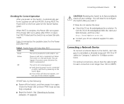
... The unit is connected correctly, and then try powering on the Switch again ■ If the Switch still does not operate, contact your 3Com network supplier If POST fails, try the following: ■ Power off the Switch, and then power it on self-test or loopback test failed....green. When POST is not longer than 100 m (328 ft). CAUTION: Resetting the Switch to reconfigure the Switch after POST, it automatically performs a power-on the front panel of the Switch flashes green. To visit the 3Com Knowledgebase Web site, start your Web browser, and then enter http://knowledgebase...
... The unit is connected correctly, and then try powering on the Switch again ■ If the Switch still does not operate, contact your 3Com network supplier If POST fails, try the following: ■ Power off the Switch, and then power it on self-test or loopback test failed....green. When POST is not longer than 100 m (328 ft). CAUTION: Resetting the Switch to reconfigure the Switch after POST, it automatically performs a power-on the front panel of the Switch flashes green. To visit the 3Com Knowledgebase Web site, start your Web browser, and then enter http://knowledgebase...

User Manual
Page 18
... The following list of approved SFP transceivers is faulty, it . See "Troubleshooting" on page 43. For 1000BASE-T operation, 3Com recommends using 3Com SFPs on the Switch. Using SFP Transceivers The following sections describe how to multimode fiber using a conditioned launch cable. If the SFP transceiver is ...publication: ■ 3CSFP91 SFP (SX) ■ 3CSFP92 SFP (LX) To access the latest list of approved SFP transceivers for the Switch on the 3Com Corporation World Wide Web site, enter this URL into any SFP port without having to a multimedia fiber-optic cable. ■ 1000BASE...
... The following list of approved SFP transceivers is faulty, it . See "Troubleshooting" on page 43. For 1000BASE-T operation, 3Com recommends using 3Com SFPs on the Switch. Using SFP Transceivers The following sections describe how to multimode fiber using a conditioned launch cable. If the SFP transceiver is ...publication: ■ 3CSFP91 SFP (SX) ■ 3CSFP92 SFP (LX) To access the latest list of approved SFP transceivers for the Switch on the 3Com Corporation World Wide Web site, enter this URL into any SFP port without having to a multimedia fiber-optic cable. ■ 1000BASE...

User Manual
Page 19
CAUTION: SFP transceivers are keyed and can be least effect on users. 3Com recommends periodically checking the items listed in Table 5. To remove an SFP transceiver: 1 Disconnect the cable from the transceiver. 2 Move the wire release lever ... cable into place. Performing Spot Checks 19 in the upright position). Removing an SFP Transceiver Removing an SFP transceiver does not require powering off the Switch. Figure 4 Inserting the SFP Transceiver Product label Wire release lever Suitable slot on the front of a possible failure; any problems can give you should ...
CAUTION: SFP transceivers are keyed and can be least effect on users. 3Com recommends periodically checking the items listed in Table 5. To remove an SFP transceiver: 1 Disconnect the cable from the transceiver. 2 Move the wire release lever ... cable into place. Performing Spot Checks 19 in the upright position). Removing an SFP Transceiver Removing an SFP transceiver does not require powering off the Switch. Figure 4 Inserting the SFP Transceiver Product label Wire release lever Suitable slot on the front of a possible failure; any problems can give you should ...

User Manual
Page 20
The fan is operating by listening to "Troubleshooting" starting on the right side of the unit (when viewed from the front). 20 CHAPTER 2: INSTALLING THE SWITCH Table 5 Items to Check Item Verify That Cabling All external cabling connections are secure and that no cables are pulled taut Cooling fan Where possible, check that the cooling fan is fitted on page 43. If you experience any problems operating the Switch, refer to the unit.
The fan is operating by listening to "Troubleshooting" starting on the right side of the unit (when viewed from the front). 20 CHAPTER 2: INSTALLING THE SWITCH Table 5 Items to Check Item Verify That Cabling All external cabling connections are secure and that no cables are pulled taut Cooling fan Where possible, check that the cooling fan is fitted on page 43. If you experience any problems operating the Switch, refer to the unit.

User Manual
Page 21
... on the Web interface. It also introduces the menu items and buttons that has a Web browser Running the Discovery Application The 3Com Baseline Switch 2226 Plus CD-ROM contains, among others, the Discovery application. To use to set the admin password, change the IP address...configure its CD drive. Discovery should start automatically, go to the \Discovery folder on 3Com Baseline Switch 2226 Plus CD-ROM that is supplied with your Switch ■ A computer that is connected to the Switch and that are covered: ■ Requirements for Accessing the Web Interface ■ Running...
... on the Web interface. It also introduces the menu items and buttons that has a Web browser Running the Discovery Application The 3Com Baseline Switch 2226 Plus CD-ROM contains, among others, the Discovery application. To use to set the admin password, change the IP address...configure its CD drive. Discovery should start automatically, go to the \Discovery folder on 3Com Baseline Switch 2226 Plus CD-ROM that is supplied with your Switch ■ A computer that is connected to the Switch and that are covered: ■ Requirements for Accessing the Web Interface ■ Running...

User Manual
Page 22
... Next. When detection is the logon screen. The Completing the 3Com Discovery Application screen appears. 4 Click Finish. Discovery searches the network for 3Com devices. On this screen, you need to enter the administration user name and password to gain access to the Switch, and then click Next. The Web interface loads in your... multiple network adapters, select the adapter that appears is complete, the Discovered Devices screen displays detected network devices. 3 On the Discovered Devices screen, click Baseline Switch 2226 Plus, and then click Next.
... Next. When detection is the logon screen. The Completing the 3Com Discovery Application screen appears. 4 Click Finish. Discovery searches the network for 3Com devices. On this screen, you need to enter the administration user name and password to gain access to the Switch, and then click Next. The Web interface loads in your... multiple network adapters, select the adapter that appears is complete, the Discovered Devices screen displays detected network devices. 3 On the Discovered Devices screen, click Baseline Switch 2226 Plus, and then click Next.

User Manual
Page 23
...Navigating the Web Interface The Web interface has been designed to enable you to configure the Switch's port settings Table 6 Available Menu Items Menu Item Description Status Provides a summary of the Switch's basic settings and versions of current components Password Allows you to change the administrator password... on the menu, the Menu Help Table 6 lists the available items on the menu. The logon screen also displays the IP address that the Switch is located on to the Web interface: 1 In Username, type admin. 2 Leave the Password field blank. 3 Click OK. Figure 7 Logon...
...Navigating the Web Interface The Web interface has been designed to enable you to configure the Switch's port settings Table 6 Available Menu Items Menu Item Description Status Provides a summary of the Switch's basic settings and versions of current components Password Allows you to change the administrator password... on the menu, the Menu Help Table 6 lists the available items on the menu. The logon screen also displays the IP address that the Switch is located on to the Web interface: 1 In Username, type admin. 2 Leave the Password field blank. 3 Click OK. Figure 7 Logon...