

User Manual
Page 12
... 12 characters such as xxSxxxxxxxxx. 1.1 System package contents Check your system package for the following items. Chassis Motherboard Accessory box ESC4000-E10S ASUS 2U Rackmount Chassis ASUS Z12PG-D16 Server Board 1 x MB Support DVD 1 x ACC instruction card 1 x Bag of Screws 2 x AC Power Cables ... 1.2 Serial number label Before requesting support from the ASUS Technical Support team, you must take note of the product, ASUS Technical Support team members can then offer a quicker and satisfying solution to your problems. ESC4000-E10S xxSxxxxxxxxx The serial number is printed on the Asset ...
... 12 characters such as xxSxxxxxxxxx. 1.1 System package contents Check your system package for the following items. Chassis Motherboard Accessory box ESC4000-E10S ASUS 2U Rackmount Chassis ASUS Z12PG-D16 Server Board 1 x MB Support DVD 1 x ACC instruction card 1 x Bag of Screws 2 x AC Power Cables ... 1.2 Serial number label Before requesting support from the ASUS Technical Support team, you must take note of the product, ASUS Technical Support team members can then offer a quicker and satisfying solution to your problems. ESC4000-E10S xxSxxxxxxxxx The serial number is printed on the Asset ...
User Manual
Page 13
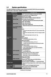
...Aspeed AST2600 64MB) Front I/O ports 4 x USB 3.2 Gen 1 ports (continued on the next page) ASUS ESC4000-E10S 1-3 1.3 System specifications The ASUS ESC4000-E10S Series servers features the ASUS Z12PG-D16 server board that supports Intel® 3rd Gen Xeon® Scalable Processors. Model Name Processor .../ System Bus ESC4000-E10S Intel® 3rd Gen Xeon® Scalable Processors (up to 235W) Memory ...
...Aspeed AST2600 64MB) Front I/O ports 4 x USB 3.2 Gen 1 ports (continued on the next page) ASUS ESC4000-E10S 1-3 1.3 System specifications The ASUS ESC4000-E10S Series servers features the ASUS Z12PG-D16 server board that supports Intel® 3rd Gen Xeon® Scalable Processors. Model Name Processor .../ System Bus ESC4000-E10S Intel® 3rd Gen Xeon® Scalable Processors (up to 235W) Memory ...

User Manual
Page 14
Combining PSUs with the same watt and power rating. System specifications Model Name ESC4000-E10S 2 x USB 3.2 Gen 1 ports Rear I/O ports 2 x Gigabit LAN ports (RJ45) 1 x Management port (RJ45) 1 x VGA port Front : 1 x Power Switch/LED 1 x Location Switch/LED 1 x HDD LED 1... 2022 RedHat® SuSE® Ubuntu Vmware * Please find the latest OS support from https://www.asus.com/ event/Server/OS_support_list/OS.html Management Out of Band Remote Hardware Solution Software ASMB10-iKVM (on-board) ASUS Control Center Dimension 800mm x 440mm x 88mm (2U) 31.50" x 17.22" x 3.46" ...
Combining PSUs with the same watt and power rating. System specifications Model Name ESC4000-E10S 2 x USB 3.2 Gen 1 ports Rear I/O ports 2 x Gigabit LAN ports (RJ45) 1 x Management port (RJ45) 1 x VGA port Front : 1 x Power Switch/LED 1 x Location Switch/LED 1 x HDD LED 1... 2022 RedHat® SuSE® Ubuntu Vmware * Please find the latest OS support from https://www.asus.com/ event/Server/OS_support_list/OS.html Management Out of Band Remote Hardware Solution Software ASMB10-iKVM (on-board) ASUS Control Center Dimension 800mm x 440mm x 88mm (2U) 31.50" x 17.22" x 3.46" ...

User Manual
Page 15
... power and location buttons, LED indicators, and USB ports are located and easily accessible on the rear panel of the server. ASUS ESC4000-E10S 1-5 Half-length / Low-profile expansion slot VGA port USB 3.2 Gen 1 ports LAN port 2 LAN port 1 DM_LAN1* ...4 Full-length Expansion slots Power cord connector and Redundant power supply 4 Full-length Expansion slots • The rear I /O shield with openings for ASUS ASMB10-iKVM controller only. Steel handle Power button Expansion card cage Location button Steel handle 1 2 3 4 5 6 7 Hot-swap 2.5-inch storage bays 8...
... power and location buttons, LED indicators, and USB ports are located and easily accessible on the rear panel of the server. ASUS ESC4000-E10S 1-5 Half-length / Low-profile expansion slot VGA port USB 3.2 Gen 1 ports LAN port 2 LAN port 1 DM_LAN1* ...4 Full-length Expansion slots Power cord connector and Redundant power supply 4 Full-length Expansion slots • The rear I /O shield with openings for ASUS ASMB10-iKVM controller only. Steel handle Power button Expansion card cage Location button Steel handle 1 2 3 4 5 6 7 Hot-swap 2.5-inch storage bays 8...

User Manual
Page 17
... HDD access LED Message LED Location button with LED LAN LEDs ON System power on OFF No activity Blinking Data activity OFF System is present ASUS ESC4000-E10S 1-7 no incoming event ON A hardware monitor event is indicated OFF Function off ON Location switch is pressed (Press the location switch again to turn off...
... HDD access LED Message LED Location button with LED LAN LEDs ON System power on OFF No activity Blinking Data activity OFF System is present ASUS ESC4000-E10S 1-7 no incoming event ON A hardware monitor event is indicated OFF Function off ON Location switch is pressed (Press the location switch again to turn off...

User Manual
Page 19
1.7.3 HDD status LEDs Red LED Green LED 1 2 3 4 5 6 7 8 2 1 1 2 3 4 5 6 7 8 2 1 SATA/SAS HDD LED Description GREEN ON SATA/SAS HDD power ON RED ON HDD has failed and should be swapped immediately GREEN/RED Blinking RAID rebuilding GREEN/RED Blinking Locate GREEN/RED OFF HDD not found GREEN Blinking Read/write data from/into the SATA/SAS HDD ASUS ESC4000-E10S 1-9
1.7.3 HDD status LEDs Red LED Green LED 1 2 3 4 5 6 7 8 2 1 1 2 3 4 5 6 7 8 2 1 SATA/SAS HDD LED Description GREEN ON SATA/SAS HDD power ON RED ON HDD has failed and should be swapped immediately GREEN/RED Blinking RAID rebuilding GREEN/RED Blinking Locate GREEN/RED OFF HDD not found GREEN Blinking Read/write data from/into the SATA/SAS HDD ASUS ESC4000-E10S 1-9

User Manual
Page 25
... to completely remove it from the chassis. 2 1 A protection film is pre-attached to completely remove it from the chassis. 2 1 To remove the front chassis cover: 1. ASUS ESC4000-E10S 2-3 To remove the middle chassis cover: 1. Please remove the protection film before shipping. Press the cover latches down , then slide the chassis cover towards the...
... to completely remove it from the chassis. 2 1 A protection film is pre-attached to completely remove it from the chassis. 2 1 To remove the front chassis cover: 1. ASUS ESC4000-E10S 2-3 To remove the middle chassis cover: 1. Please remove the protection film before shipping. Press the cover latches down , then slide the chassis cover towards the...

User Manual
Page 27
... resulting from incorrect CPU installation/removal, or misplacement/loss/incorrect removal of the PnP cap. 2.2.1 Installing the CPU and heatsink 1. ASUS will process Return Merchandise Authorization (RMA) requests only if the motherboard comes with a surface mount Socket P+ designed for 3rd Generation...The motherboard comes with the cap on the motherboard. ASUS will shoulder the cost of the motherboard, ensure that the PnP cap is shipment/ transit-related. • Keep the cap after installing the motherboard. Remove the air duct. Remove the rear chassis cover. ASUS ESC4000-E10S 2-5
... resulting from incorrect CPU installation/removal, or misplacement/loss/incorrect removal of the PnP cap. 2.2.1 Installing the CPU and heatsink 1. ASUS will process Return Merchandise Authorization (RMA) requests only if the motherboard comes with a surface mount Socket P+ designed for 3rd Generation...The motherboard comes with the cap on the motherboard. ASUS will shoulder the cost of the motherboard, ensure that the PnP cap is shipment/ transit-related. • Keep the cap after installing the motherboard. Remove the air duct. Remove the rear chassis cover. ASUS ESC4000-E10S 2-5

User Manual
Page 29
...Carrier fits in the same direction, then place the heatsinks on top of the CPU sockets (A). The heatsink for more information on the socket. ASUS ESC4000-E10S 2-7 5. Align the CPU and heatsink assembly in the correct orientation so that the heatsink and CPU assembly is located in the same corner as... the CPU socket. DO NOT force the CPU and CPU Carrier into the socket to the illustration below for ESC4000-E10S differs between CPU1 and CPU2, please refer to prevent damaging the CPU pins on the heatsink and the corresponding CPU socket. Ensure the ...
...Carrier fits in the same direction, then place the heatsinks on top of the CPU sockets (A). The heatsink for more information on the socket. ASUS ESC4000-E10S 2-7 5. Align the CPU and heatsink assembly in the correct orientation so that the heatsink and CPU assembly is located in the same corner as... the CPU socket. DO NOT force the CPU and CPU Carrier into the socket to the illustration below for ESC4000-E10S differs between CPU1 and CPU2, please refer to prevent damaging the CPU pins on the heatsink and the corresponding CPU socket. Ensure the ...

User Manual
Page 31
... • 2 DIMMs • • 4 DIMMs • • • • 6 DIMMs • • • • • • 8 DIMMs • • • • • • • • ASUS ESC4000-E10S 2-9 The figure illustrates the location of compatible DIMMs. • Always install DIMMs with sixteen (16) Double Data Rate 4 (DDR4) Dual Inline Memory Modules (DIMM) sockets...
... • 2 DIMMs • • 4 DIMMs • • • • 6 DIMMs • • • • • • 8 DIMMs • • • • • • • • ASUS ESC4000-E10S 2-9 The figure illustrates the location of compatible DIMMs. • Always install DIMMs with sixteen (16) Double Data Rate 4 (DDR4) Dual Inline Memory Modules (DIMM) sockets...

User Manual
Page 33
... retaining clips outward. Failure to do so may cause severe damage to unplug the power supply before adding or removing DIMMs or other system components. ASUS ESC4000-E10S 2-11 Align a DIMM on the socket such that it fits in the wrong direction to the Chassis cover section. 2.3.3 Installing a DIMM on a single clip DIMM...
... retaining clips outward. Failure to do so may cause severe damage to unplug the power supply before adding or removing DIMMs or other system components. ASUS ESC4000-E10S 2-11 Align a DIMM on the socket such that it fits in the wrong direction to the Chassis cover section. 2.3.3 Installing a DIMM on a single clip DIMM...

User Manual
Page 35
... bay. Press the spring lock to release the tray lever and to storage device bays 3 and 4. 2.4.1 To install a 2.5" hot-swap SATA/SAS/NVMe storage device 1. ASUS ESC4000-E10S 2 1 2-13 2.4 Storage devices The system supports eight (8) 2.5" hot-swap SATA/SAS/NVMe storage devices (up to 4 x NVMe/SAS/SATA + 4 x SAS/SATA...
... bay. Press the spring lock to release the tray lever and to storage device bays 3 and 4. 2.4.1 To install a 2.5" hot-swap SATA/SAS/NVMe storage device 1. ASUS ESC4000-E10S 2 1 2-13 2.4 Storage devices The system supports eight (8) 2.5" hot-swap SATA/SAS/NVMe storage devices (up to 4 x NVMe/SAS/SATA + 4 x SAS/SATA...

User Manual
Page 37
... injury and damage motherboard components. 2.5.1 The PCI Express riser card The onboard PCI Express slot on the motherboard. 2.5 Expansion slots Ensure to the riser card: 1. ASUS ESC4000-E10S 2-15 PCIe x16 slot low-profile PCIe x16 slot low-profile To install PCIe expansion cards to unplug the power cord before adding or removing...
... injury and damage motherboard components. 2.5.1 The PCI Express riser card The onboard PCI Express slot on the motherboard. 2.5 Expansion slots Ensure to the riser card: 1. ASUS ESC4000-E10S 2-15 PCIe x16 slot low-profile PCIe x16 slot low-profile To install PCIe expansion cards to unplug the power cord before adding or removing...

User Manual
Page 39
Secure the riser card with the two (2) screws that you removed earlier in one orientation only. Align and insert the riser card and expansion card assembly into the PCIe slot on the motherboard. PCIe slot riser card and expansion card assembly ASUS ESC4000-E10S 2-17 If it does not fit, try reversing it. 8. The expansion card fits in step 1. 2 1 7.
Secure the riser card with the two (2) screws that you removed earlier in one orientation only. Align and insert the riser card and expansion card assembly into the PCIe slot on the motherboard. PCIe slot riser card and expansion card assembly ASUS ESC4000-E10S 2-17 If it does not fit, try reversing it. 8. The expansion card fits in step 1. 2 1 7.

User Manual
Page 41
3. ASUS ESC4000-E10S 2-19 Align the three screw holes on the Cache Vault Power Module clip to the cable from the Cache Vault Power Module to the three screw holes on the ASUS PIKE II card. Connect the cable from the Cache Vault Flash Module on the Cache Vault Power Module clip holder, then secure the clip with the bundled three (3) screws and three (3) bundled nuts. 4. Align and install the Cache Vault Power Module into the Cache Vault Power Module clip. 5.
3. ASUS ESC4000-E10S 2-19 Align the three screw holes on the Cache Vault Power Module clip to the cable from the Cache Vault Power Module to the three screw holes on the ASUS PIKE II card. Connect the cable from the Cache Vault Flash Module on the Cache Vault Power Module clip holder, then secure the clip with the bundled three (3) screws and three (3) bundled nuts. 4. Align and install the Cache Vault Power Module into the Cache Vault Power Module clip. 5.
User Manual
Page 43
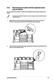
2.5.3 Reconnecting the cable to the M.2 expansion board (only for PCIe slot to enable the M.2 expansion board located in the front of the system. ASUS ESC4000-E10S 2-21 Connect the two (2) slimline SAS cables removed from the internal riser board for PCIe slot, if your system package comes with the M.2 expansion board ...
2.5.3 Reconnecting the cable to the M.2 expansion board (only for PCIe slot to enable the M.2 expansion board located in the front of the system. ASUS ESC4000-E10S 2-21 Connect the two (2) slimline SAS cables removed from the internal riser board for PCIe slot, if your system package comes with the M.2 expansion board ...
User Manual
Page 45
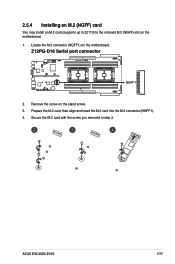
Remove the screw on the motherboard. 1. Secure the M.2 card with the screw you removed in step 2. ASUS ESC4000-E10S 2-23 Prepare the M.2 card, then align and insert the M.2 card into the M.2 connector (NGFF1). 4. 2.5.4 Installing an M.2 (NGFF) card You may install an M.2 card (supports up to 22110) to the onboard M.2 (NGFF) slot on the stand screw. 3. Locate the M.2 connector (NGFF1) on the motherboard. 2.
Remove the screw on the motherboard. 1. Secure the M.2 card with the screw you removed in step 2. ASUS ESC4000-E10S 2-23 Prepare the M.2 card, then align and insert the M.2 card into the M.2 connector (NGFF1). 4. 2.5.4 Installing an M.2 (NGFF) card You may install an M.2 card (supports up to 22110) to the onboard M.2 (NGFF) slot on the stand screw. 3. Locate the M.2 connector (NGFF1) on the motherboard. 2.
User Manual
Page 47
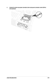
3. Connect the white 4-pin power connector to the 4-pin power connector on the OCP3.0 slot baseboard. 2 1 2 1 ASUS ESC4000-E10S 2-25
3. Connect the white 4-pin power connector to the 4-pin power connector on the OCP3.0 slot baseboard. 2 1 2 1 ASUS ESC4000-E10S 2-25
User Manual
Page 49
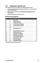
... information on the system and change the necessary BIOS settings, if any. Install the software drivers for ISA or PCI devices. Turn on BIOS setup. 2. ASUS ESC4000-E10S 2-27 2.5.7 Configuring an expansion card After installing the expansion card, configure it by adjusting the software settings. 1.
... information on the system and change the necessary BIOS settings, if any. Install the software drivers for ISA or PCI devices. Turn on BIOS setup. 2. ASUS ESC4000-E10S 2-27 2.5.7 Configuring an expansion card After installing the expansion card, configure it by adjusting the software settings. 1.
User Manual
Page 51
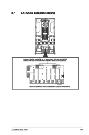
2.7 SATA/SAS backplane cabling connect to support 2 NVMe devices. With two mini-SAS HD cables connected, a total number of 8 SAS/SATA HDDs can be supported connect to SLIMPCIE2 on the motherboard to ISATA1 and ISATA2 on the motherboard. ASUS ESC4000-E10S 2-29
2.7 SATA/SAS backplane cabling connect to support 2 NVMe devices. With two mini-SAS HD cables connected, a total number of 8 SAS/SATA HDDs can be supported connect to SLIMPCIE2 on the motherboard to ISATA1 and ISATA2 on the motherboard. ASUS ESC4000-E10S 2-29