

Getting Started Guide
Page 2
... (design/logo), ATC, AUGI, AutoCAD, AutoCAD Learning Assistance, AutoCAD LT, AutoCAD Simulator, AutoCAD SQL Extension, AutoCAD SQL Interface, Autodesk, Autodesk Envision, Autodesk Insight, Autodesk Intent, Autodesk Inventor, Autodesk Map, Autodesk MapGuide, Autodesk Streamline, AutoLISP, AutoSnap, AutoSketch, AutoTrack, Backdraft, Built with ObjectARX (logo), Burn, Buzzsaw, CAiCE, Can You Imagine, Character Studio, Cinestream, Civil 3D, Cleaner, Cleaner Central, ClearScale, Colour Warper, Combustion, Communication Specification, Constructware, Content Explorer, Create>what's>Next> (design/logo...
... (design/logo), ATC, AUGI, AutoCAD, AutoCAD Learning Assistance, AutoCAD LT, AutoCAD Simulator, AutoCAD SQL Extension, AutoCAD SQL Interface, Autodesk, Autodesk Envision, Autodesk Insight, Autodesk Intent, Autodesk Inventor, Autodesk Map, Autodesk MapGuide, Autodesk Streamline, AutoLISP, AutoSnap, AutoSketch, AutoTrack, Backdraft, Built with ObjectARX (logo), Burn, Buzzsaw, CAiCE, Can You Imagine, Character Studio, Cinestream, Civil 3D, Cleaner, Cleaner Central, ClearScale, Colour Warper, Combustion, Communication Specification, Constructware, Content Explorer, Create>what's>Next> (design/logo...

Getting Started Guide
Page 4
Add Loads 18 Add Contact Conditions 19 Generate a Mesh 20 Run the Simulation 20 Run Modal Analysis 21 Chapter 3 View Results 23 Use Results Visualization 23 Edit the Color Bar 25 Read Stress Analysis Results 26 Interpret Results Contours 26 Animate Results 27 Set Results Display Options 28 Chapter 4 Revise Models and Stress Analyses 31 Change Model Geometry 31 Change Solution Conditions 32 Update Results of Stress Analysis...
Add Loads 18 Add Contact Conditions 19 Generate a Mesh 20 Run the Simulation 20 Run Modal Analysis 21 Chapter 3 View Results 23 Use Results Visualization 23 Edit the Color Bar 25 Read Stress Analysis Results 26 Interpret Results Contours 26 Animate Results 27 Set Results Display Options 28 Chapter 4 Revise Models and Stress Analyses 31 Change Model Geometry 31 Change Solution Conditions 32 Update Results of Stress Analysis...
Getting Started Guide
Page 9
... Analysis in this manual is an add-on to analyze loads and constraints placed on the Autodesk Inventor application, Autodesk Inventor Simulation includes several different modules. You can visualize the affects in Autodesk Inventor Simulation. 3 This manual provides basic conceptual information to help get you to find natural frequencies of vibration and mode shapes of Stress and Modal Analysis in 3D volume plots, create reports for completing complex...
... Analysis in this manual is an add-on to analyze loads and constraints placed on the Autodesk Inventor application, Autodesk Inventor Simulation includes several different modules. You can visualize the affects in Autodesk Inventor Simulation. 3 This manual provides basic conceptual information to help get you to find natural frequencies of vibration and mode shapes of Stress and Modal Analysis in 3D volume plots, create reports for completing complex...

Getting Started Guide
Page 10
... in the Autodesk Inventor Simulation Getting Started manual. Enhance your productivity with hands-on, instructor-led classes to : ■ Use the assembly, part modeling, and sketch environments and browsers. ■ Edit a component in the Autodesk Inventor Simulation modules as well as the standard Autodesk Inventor Simulation features. If you do not, use the Table of Contents to navigate to have a working knowledge of concepts for Help with Autodesk® software. For more productive with the...
... in the Autodesk Inventor Simulation Getting Started manual. Enhance your productivity with hands-on, instructor-led classes to : ■ Use the assembly, part modeling, and sketch environments and browsers. ■ Edit a component in the Autodesk Inventor Simulation modules as well as the standard Autodesk Inventor Simulation features. If you do not, use the Table of Contents to navigate to have a working knowledge of concepts for Help with Autodesk® software. For more productive with the...

Getting Started Guide
Page 13
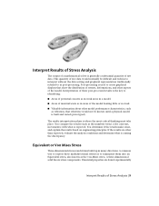
... vibration effects, geometry plays a critical role in the design phase can be the difference between failure and expected performance. Proper use : When designing bracketry or single piece weldments, the deformation of your simulation is divided into smaller elements. Understand How Stress Analysis Works Stress analysis is referred to your part may greatly affect the alignment of critical components...
... vibration effects, geometry plays a critical role in the design phase can be the difference between failure and expected performance. Proper use : When designing bracketry or single piece weldments, the deformation of your simulation is divided into smaller elements. Understand How Stress Analysis Works Stress analysis is referred to your part may greatly affect the alignment of critical components...
Getting Started Guide
Page 15
... as the numbers versus color contours, movements) with what is to create graphical displays that otherwise would normally be known until a physical model is built and tested (prototyped). The results interpretation phase is expected. If the results are found experimentally Interpret Results of raw data. A common way to express these post-processed results is used to summarize them...
... as the numbers versus color contours, movements) with what is to create graphical displays that otherwise would normally be known until a physical model is built and tested (prototyped). The results interpretation phase is expected. If the results are found experimentally Interpret Results of raw data. A common way to express these post-processed results is used to summarize them...
Getting Started Guide
Page 20
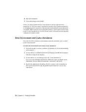
... make them current with respect to the browser node indicates areas that need an update. By default you want to use different materials, constraints, and loads. 4 Specify the simulation properties. Specify a name, type of simulation, and on the Model State tab, the model representation to analyze. To enter the environment and create a new simulation: 1 Open the model you are in the Manage panel ➤ Create Simulation. The Stress Analysis tab displays...
... make them current with respect to the browser node indicates areas that need an update. By default you want to use different materials, constraints, and loads. 4 Specify the simulation properties. Specify a name, type of simulation, and on the Model State tab, the model representation to analyze. To enter the environment and create a new simulation: 1 Open the model you are in the Manage panel ➤ Create Simulation. The Stress Analysis tab displays...
Getting Started Guide
Page 24
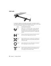
... linear acceleration for the model using planar faces, straight edges, two vertices, and axes. You can be encountered. Apply pressure only to the surface at all locations on the surface. Define the direction planar faces, straight edges, and axes. By default, the applied load is radial. Add Loads To simulate conditions your design can encounter, you add force loads to areas where...
... linear acceleration for the model using planar faces, straight edges, two vertices, and axes. You can be encountered. Apply pressure only to the surface at all locations on the surface. Define the direction planar faces, straight edges, and axes. By default, the applied load is radial. Add Loads To simulate conditions your design can encounter, you add force loads to areas where...

Getting Started Guide
Page 25
... specify the tolerance and type of gravitational load on the model. To add a load, you must: 1 Click the load command corresponding to the load type you want to add. 2 The selection command is necessary to the load you can select the geometry appropriate to manually add contacts. Automatic Contacts To automatically add contact conditions, click the Automatic Contacts command. Select a face to define the direction or use Vector Components to access the advanced settings.
... specify the tolerance and type of gravitational load on the model. To add a load, you must: 1 Click the load command corresponding to the load type you want to add. 2 The selection command is necessary to the load you can select the geometry appropriate to manually add contacts. Automatic Contacts To automatically add contact conditions, click the Automatic Contacts command. Select a face to define the direction or use Vector Components to access the advanced settings.

Getting Started Guide
Page 27
... appropriate materials. 4 Apply the necessary constraints (optional). 5 Apply any loads (optional). 6 Make adjustments to find the natural frequencies at which your part vibrates, and the mode shapes at those sections that the material used for the first eight frequency modes are essentially zero. 8 To change the number of frequencies displayed right click the Simulation node (near the top of the browser), and select Edit Simulation Properties. Run...
... appropriate materials. 4 Apply the necessary constraints (optional). 5 Apply any loads (optional). 6 Make adjustments to find the natural frequencies at which your part vibrates, and the mode shapes at those sections that the material used for the first eight frequency modes are essentially zero. 8 To change the number of frequencies displayed right click the Simulation node (near the top of the browser), and select Edit Simulation Properties. Run...

Getting Started Guide
Page 31
... 5 colors are used and these controls are disabled. 3 To increase or decrease the number of colors you want to 12. NOTE It does not work for values at specific points. By default, the maximum and minimum values shown on the grayscale, click Grayscale under Color Type. You can edit the color bar to set up the color contours so that the stress/displacement is displayed in...
... 5 colors are used and these controls are disabled. 3 To increase or decrease the number of colors you want to 12. NOTE It does not work for values at specific points. By default, the maximum and minimum values shown on the grayscale, click Grayscale under Color Type. You can edit the color bar to set up the color contours so that the stress/displacement is displayed in...
Getting Started Guide
Page 32
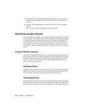
... the color bar at a different location. 6 For Size, select an appropriate option to the loading conditions. 26 | Chapter 3 View Results If your initial analysis is a natural frequency analysis, the results set gives you the stresses calculated during the solution for the first mode displays. Interpret Results Contours The contour colors display in the legend. Von Mises Stress Von Mises stress results use color contours...
... the color bar at a different location. 6 For Size, select an appropriate option to the loading conditions. 26 | Chapter 3 View Results If your initial analysis is a natural frequency analysis, the results set gives you the stresses calculated during the solution for the first mode displays. Interpret Results Contours The contour colors display in the legend. Von Mises Stress Von Mises stress results use color contours...

Getting Started Guide
Page 34
... Displays color changes using a strict banding between colors. Minimum Turns on the part. 28 | Chapter 3 View Results Color Bar Displays the Color Bar settings dialog box where you can use the following commands located on and off the Shaded Results display. Turns on the Result and Display panels to Same Scale Maintains the same scale while viewing different results. Set Results Display Options While viewing your model. Command Used to modify the features of minimum result in the mode...
... Displays color changes using a strict banding between colors. Minimum Turns on the part. 28 | Chapter 3 View Results Color Bar Displays the Color Bar settings dialog box where you can use the following commands located on and off the Shaded Results display. Turns on the Result and Display panels to Same Scale Maintains the same scale while viewing different results. Set Results Display Options While viewing your model. Command Used to modify the features of minimum result in the mode...

Getting Started Guide
Page 35
... to Activates the Probe command. Use the Displacement Scale pull-down list to scale. Mesh View Displays the element mesh used in the solution in areas of the deformation is more pronounced. Select Actualto see the deformation to adjust the deformed shape exaggeration. You place probes as needed in conjunction with the result contours. Set Results Display Options | 29 The values...
... to Activates the Probe command. Use the Displacement Scale pull-down list to scale. Mesh View Displays the element mesh used in the solution in areas of the deformation is more pronounced. Select Actualto see the deformation to adjust the deformed shape exaggeration. You place probes as needed in conjunction with the result contours. Set Results Display Options | 29 The values...
Getting Started Guide
Page 38
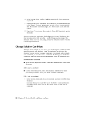
... Models and Stress Analyses Then click Simulate to have current analysis data. 6 At the bottom of date with the load changes orientation. Your component is necessary, right-click the Contacts node, and click Update. 8 Repeat step 7 for that requires it . Add a load or constraint ■ On the Stress Analysis tab, select the command and follow the same procedure you used to the change the...
... Models and Stress Analyses Then click Simulate to have current analysis data. 6 At the bottom of date with the load changes orientation. Your component is necessary, right-click the Contacts node, and click Update. 8 Repeat step 7 for that requires it . Add a load or constraint ■ On the Stress Analysis tab, select the command and follow the same procedure you used to the change the...

Getting Started Guide
Page 45
... the model file. The Save Copy As command copies all results are also saved in a dedicated folder of the same name as needed. You can turn off the links by changing the option. By default, OLE links are stored in separate files. In addition, the model file is no reason to each of the Mesh and Result data. Stress Analysis input and results information, including loads, constraints...
... the model file. The Save Copy As command copies all results are also saved in a dedicated folder of the same name as needed. You can turn off the links by changing the option. By default, OLE links are stored in separate files. In addition, the model file is no reason to each of the Mesh and Result data. Stress Analysis input and results information, including loads, constraints...
Getting Started Guide
Page 50
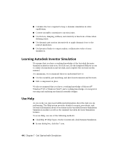
... a working knowledge of concepts for access to online documentation and tutorials, and complete the exercises in the Autodesk Inventor Simulation Simulation modules as well as functions of time when defining joints. ■ Use dynamic part motion interactively to apply dynamic force to the jointed simulation. ■ Use Inventor Studio to output realistic or illustrative video of the following methods: ■ Click Help ➤ Help Topics. On the Contents tab...
... a working knowledge of concepts for access to online documentation and tutorials, and complete the exercises in the Autodesk Inventor Simulation Simulation modules as well as functions of time when defining joints. ■ Use dynamic part motion interactively to apply dynamic force to the jointed simulation. ■ Use Inventor Studio to output realistic or illustrative video of the following methods: ■ Click Help ➤ Help Topics. On the Contents tab...
Getting Started Guide
Page 56
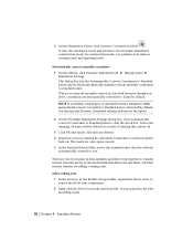
... will be deleted as creating joints and applying loads. Add that motion transfer by default. Add a rolling joint 1 In the browser, in Autodesk Inventor Simulation 2010, constraints are automatically converted to the mechanism that the software automatically created for you perform such tasks as a result of turning this assembly and they work together to transfer motion from the motor to joints by default. Automatically convert assembly constraints...
... will be deleted as creating joints and applying loads. Add that motion transfer by default. Add a rolling joint 1 In the browser, in Autodesk Inventor Simulation 2010, constraints are automatically converted to the mechanism that the software automatically created for you perform such tasks as a result of turning this assembly and they work together to transfer motion from the motor to joints by default. Automatically convert assembly constraints...
Getting Started Guide
Page 73
... 8 modal 21 post processing 9 reports 35 rerunning on edited designs 31 results, reading 23, 26 solving 7 types, setting 33 updating 34 vibration 11 analysis (.ipa) files repairing disassociated 40 ANSYS WorkBench 43 B Boundary Condition command 28 browser, Stress Analysis 13 C coherent masses and inertia 46 color bar 24 constraints assembly 49 browser display 17 converting assembly 50 deleting, adding, and editing 32 continuity of laws...
... 8 modal 21 post processing 9 reports 35 rerunning on edited designs 31 results, reading 23, 26 solving 7 types, setting 33 updating 34 vibration 11 analysis (.ipa) files repairing disassociated 40 ANSYS WorkBench 43 B Boundary Condition command 28 browser, Stress Analysis 13 C coherent masses and inertia 46 color bar 24 constraints assembly 49 browser display 17 converting assembly 50 deleting, adding, and editing 32 continuity of laws...
Getting Started Guide
Page 74
L load symbols 32 displaying 28, 33 loads browser display 17 deleting, adding, and editing 32 M meshes creating 8 displaying 29 Minimum command 28 modal analyses 11, 21 model geometry, editing 31 modes frequency 11 result options 21 N natural resonant frequencies 11 O Output Grapher 61 P panel bar, Stress Analysis 13 post processing analyses 9 preprocessing 8 prerequisites for exercises 4 R relative parameters 45 Report command 35 reports printing and distributing 38 saving 35 resonant...
L load symbols 32 displaying 28, 33 loads browser display 17 deleting, adding, and editing 32 M meshes creating 8 displaying 29 Minimum command 28 modal analyses 11, 21 model geometry, editing 31 modes frequency 11 result options 21 N natural resonant frequencies 11 O Output Grapher 61 P panel bar, Stress Analysis 13 post processing analyses 9 preprocessing 8 prerequisites for exercises 4 R relative parameters 45 Report command 35 reports printing and distributing 38 saving 35 resonant...
