

User Manual
Page 1
... the vendor reserves the right to revise this publication, in part or in whole, is no representations or warranties with respect to notify any purpose. K8T800-A7A FCC Information and Copyright This equipment has been tested and found in this user's manual is subject to radio communications. These limits are trademarks of...
... the vendor reserves the right to revise this publication, in part or in whole, is no representations or warranties with respect to notify any purpose. K8T800-A7A FCC Information and Copyright This equipment has been tested and found in this user's manual is subject to radio communications. These limits are trademarks of...
User Manual
Page 3
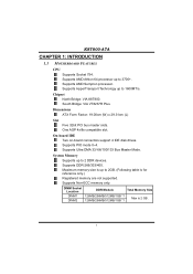
...Supports AMD Athlon 64 processor up to 3700+. On-board IDE Two on-board connectors support 4 IDE disk drives. Supports DDR-266/333/400. K8T800-A7A CHAPTER 1: INTRODUCTION 1.1 MOTHERBOARD FEATURES CPU Supports Socket 754. South Bridge: VIA VT8237R Plus. Supports PIO mode 0~4. Supports HyperTransport Technology up to 1600MT... *1 Max is up to 2GB. (Following table is for reference only.) Registered memory are not supported. Chipset North Bridge: VIA K8T800. Maximum memory size is 2 GB. 1 Supports AMD Sempron processor. Supports Ultra DMA 33/ 66/100/133 Bus Master Mode.
...Supports AMD Athlon 64 processor up to 3700+. On-board IDE Two on-board connectors support 4 IDE disk drives. Supports DDR-266/333/400. K8T800-A7A CHAPTER 1: INTRODUCTION 1.1 MOTHERBOARD FEATURES CPU Supports Socket 754. South Bridge: VIA VT8237R Plus. Supports PIO mode 0~4. Supports HyperTransport Technology up to 1600MT... *1 Max is up to 2GB. (Following table is for reference only.) Registered memory are not supported. Chipset North Bridge: VIA K8T800. Maximum memory size is 2 GB. 1 Supports AMD Sempron processor. Supports Ultra DMA 33/ 66/100/133 Bus Master Mode.

User Manual
Page 4
... rates up to 150 MB/s. - Support 6 channels. Provides the most commonly used legacy Super I /O Chip: ITE 8705AF. Half/Full duplex capability. Low Pin Count Interface. K8T800-A7A Super I /O functionality. Onboard AC'97 Sound CODEC Chip: REALTEK ALC655. Supports ACPI, PCI power management. 2
... rates up to 150 MB/s. - Support 6 channels. Provides the most commonly used legacy Super I /O Chip: ITE 8705AF. Half/Full duplex capability. Low Pin Count Interface. K8T800-A7A Super I /O functionality. Onboard AC'97 Sound CODEC Chip: REALTEK ALC655. Supports ACPI, PCI power management. 2
User Manual
Page 5
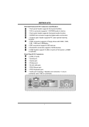
LAN PS/2 Mouse Printer port GAME Port PS/2 Keyboard USB x2 COM1 Speaker Out Line In Mic In 3 K8T800-A7A Internal On-board I/O Connectors and Headers 1 front panel header supports front panel facilities. 1 CD-in connector supports 1 CD-ROM audio-in device. 1 front audio header ...
LAN PS/2 Mouse Printer port GAME Port PS/2 Keyboard USB x2 COM1 Speaker Out Line In Mic In 3 K8T800-A7A Internal On-board I/O Connectors and Headers 1 front panel header supports front panel facilities. 1 CD-in connector supports 1 CD-ROM audio-in device. 1 front audio header ...

User Manual
Page 7
K8T800-A7A CHAPTER 2: HARDWARE INSTALLATION 2.1 INSTALLING CENTRAL PROCESSING UNIT (CPU) Step 1: Pull the lever toward direction A from the socket and then raise the lever up to the JCFAN1. Step 4: Put the CPU Fan on CPU should point forwards this cut edge. This completes the installation. 5 Connect the CPU FAN power cable to a 90-degree angle. 90 A Step 2: Look for the cut edge on socket, and the gold triangle on the CPU and buckle it. The CPU will fit only in the correct orientation. Step 3: Hold the CPU down firmly, and then close the lever to complete the installation.
K8T800-A7A CHAPTER 2: HARDWARE INSTALLATION 2.1 INSTALLING CENTRAL PROCESSING UNIT (CPU) Step 1: Pull the lever toward direction A from the socket and then raise the lever up to the JCFAN1. Step 4: Put the CPU Fan on CPU should point forwards this cut edge. This completes the installation. 5 Connect the CPU FAN power cable to a 90-degree angle. 90 A Step 2: Look for the cut edge on socket, and the gold triangle on the CPU and buckle it. The CPU will fit only in the correct orientation. Step 3: Hold the CPU down firmly, and then close the lever to complete the installation.

User Manual
Page 8
... wire is the positive and should be connected to pin#2, and the black wire is Ground and should be different according to the fan manufacturer. K8T800-A7A 2.2 FAN HEADERS These fan headers support cooling-fans built in the computer. The fan cable and connector may be connected to pin#1.
... wire is the positive and should be connected to pin#2, and the black wire is Ground and should be different according to the fan manufacturer. K8T800-A7A 2.2 FAN HEADERS These fan headers support cooling-fans built in the computer. The fan cable and connector may be connected to pin#1.
User Manual
Page 9
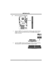
Unlock a DIMM slot by pressing the retaining clips outward. Align a DIMM on the slot such that the notch on the DIMM matches the break on the Slot. 2. DIMM1 DIMM2 K8T800-A7A 2.3 INSTALLING SYSTEM MEMORY 1. Insert the DIMM vertically and firmly into the slot until the retaining chip snap back in place and the DIMM is properly seated. 7
Unlock a DIMM slot by pressing the retaining clips outward. Align a DIMM on the slot such that the notch on the DIMM matches the break on the Slot. 2. DIMM1 DIMM2 K8T800-A7A 2.3 INSTALLING SYSTEM MEMORY 1. Insert the DIMM vertically and firmly into the slot until the retaining chip snap back in place and the DIMM is properly seated. 7

User Manual
Page 10
The first hard drive should always be connected to four hard disk drives. K8T800-A7A 2.4 CONNECTORS AND SLOTS FDD1: Floppy Disk Connector The motherboard provides a standard floppy disk connector that provides PIO Mode 0~4, Bus Master, and Ultra DMA 33/66/...
The first hard drive should always be connected to four hard disk drives. K8T800-A7A 2.4 CONNECTORS AND SLOTS FDD1: Floppy Disk Connector The motherboard provides a standard floppy disk connector that provides PIO Mode 0~4, Bus Master, and Ultra DMA 33/66/...

User Manual
Page 11
... take advantage of AGP technology for improved video efficiency and performance, especially with 3D graphics. An AGP card will attach directly to that video card. K8T800-A7A PCI1~PCI5: Peripheral Component Interconnect Slots This motherboard is equipped with an Accelerated Graphics Port (AGP). This motherboard supports video cards for PCI slots, but...
... take advantage of AGP technology for improved video efficiency and performance, especially with 3D graphics. An AGP card will attach directly to that video card. K8T800-A7A PCI1~PCI5: Peripheral Component Interconnect Slots This motherboard is equipped with an Accelerated Graphics Port (AGP). This motherboard supports video cards for PCI slots, but...

User Manual
Page 12
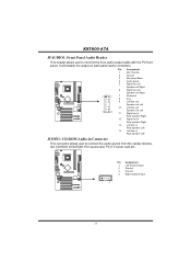
... 3.2 DETAIL SETTINGS JPANEL1: Front Panel Header This 22-pin connector includes Power-on, Reset, HDD LED, Power LED, Sleep button, speaker and IrDA Connection (optional). K8T800-A7A CHAPTER 3: HEADERS & JUMPERS SETUP 3.1 HOW TO SETUP JUMPERS The illustration shows how to connect the PC case's front panel switch functions.
... 3.2 DETAIL SETTINGS JPANEL1: Front Panel Header This 22-pin connector includes Power-on, Reset, HDD LED, Power LED, Sleep button, speaker and IrDA Connection (optional). K8T800-A7A CHAPTER 3: HEADERS & JUMPERS SETUP 3.1 HOW TO SETUP JUMPERS The illustration shows how to connect the PC case's front panel switch functions.

User Manual
Page 13
... powered by +5V standby voltage. JUSBV2: +5V for USB ports at JUSBLAN1. Pin 2-3 Close: JUSBV1: USB ports at JUSBLAN1 are powered by +5V standby voltage. K8T800-A7A JUSB1/JUSB2/JUSB3: Headers for USB 2.0 Ports at Front Panel (JUSB3 is optional) This header allows user to support this function "Power-On system via...
... powered by +5V standby voltage. JUSBV2: +5V for USB ports at JUSBLAN1. Pin 2-3 Close: JUSBV1: USB ports at JUSBLAN1 are powered by +5V standby voltage. K8T800-A7A JUSB1/JUSB2/JUSB3: Headers for USB 2.0 Ports at Front Panel (JUSB3 is optional) This header allows user to support this function "Power-On system via...
User Manual
Page 14
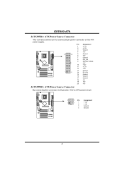
Pin Assignment 1 +3.3V 2 +3.3V 3 Ground 4 +5V 10 20 5 Ground 6 +5V 7 Ground 8 PW_OK 9 Standby Voltage +5V 10 +12V 11 +3.3V 12 -12V 13 Ground 1 11 14 PS_ON 15 Ground 16 Ground 17 Ground 18 -5V 19 +5V 20 +5V JATXPWR2: ATX Power Source Connector By connecting this connector, it will provide +12V to connect 20-pin power connector on the ATX power supply. K8T800-A7A JATXPWR1: ATX Power Source Connector This connector allows user to CPU power circuit. 4 3 Pin Assignment 2 1 1 +12V 2 +12V 3 Ground 4 Ground 12
Pin Assignment 1 +3.3V 2 +3.3V 3 Ground 4 +5V 10 20 5 Ground 6 +5V 7 Ground 8 PW_OK 9 Standby Voltage +5V 10 +12V 11 +3.3V 12 -12V 13 Ground 1 11 14 PS_ON 15 Ground 16 Ground 17 Ground 18 -5V 19 +5V 20 +5V JATXPWR2: ATX Power Source Connector By connecting this connector, it will provide +12V to connect 20-pin power connector on the ATX power supply. K8T800-A7A JATXPWR1: ATX Power Source Connector This connector allows user to CPU power circuit. 4 3 Pin Assignment 2 1 1 +12V 2 +12V 3 Ground 4 Ground 12
User Manual
Page 15
K8T800-A7A JFAUDIO1: Front Panel Audio Header This header allows user to connect the audio source from the variaty devices, like CD-ROM, DVD-ROM, PCI sound ...
K8T800-A7A JFAUDIO1: Front Panel Audio Header This header allows user to connect the audio source from the variaty devices, like CD-ROM, DVD-ROM, PCI sound ...

User Manual
Page 16
K8T800-A7A JCMOS1: Clear CMOS Header By placing the jumper on pin2-3, it will record to the CMOS and show the message on the AC. 6. Set the ...
K8T800-A7A JCMOS1: Clear CMOS Header By placing the jumper on pin2-3, it will record to the CMOS and show the message on the AC. 6. Set the ...
User Manual
Page 17
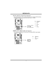
K8T800-A7A JSATA1~JSATA2: Serial ATA Connectors The motherboard has a PCI to SATA Controller with 2 channels SATA interface, it satisfies the SATA 1.0 spec and with transfer rate of 1.5GB/s. 741 JSATA1 Pin Assignment 1 Ground 2 TX+ 3 TX4 Ground 5 RX6 RX+ 7 Ground JSPDIF_OUT1: Digital Audio-out Connector This connector allows user to connect the PCI bracket SPDIF output header. 1 3 Pin Assignment 1 +5V 2 SPDIF_OUT 3 Ground 15
K8T800-A7A JSATA1~JSATA2: Serial ATA Connectors The motherboard has a PCI to SATA Controller with 2 channels SATA interface, it satisfies the SATA 1.0 spec and with transfer rate of 1.5GB/s. 741 JSATA1 Pin Assignment 1 Ground 2 TX+ 3 TX4 Ground 5 RX6 RX+ 7 Ground JSPDIF_OUT1: Digital Audio-out Connector This connector allows user to connect the PCI bracket SPDIF output header. 1 3 Pin Assignment 1 +5V 2 SPDIF_OUT 3 Ground 15

User Manual
Page 18
K8T800-A7A CHAPTER 4: USEFUL HELP 4.1 AWARD BIOS BEEP CODE Beep Sound One long beep ...been recovered and will update BIOS automatically and restart. 9. Confirm motherboard model and download the respectively BIOS from the Biostar website: www.biostar.com.tw 3. Type "Awdflash xxxx.bf/sn/py/r" in DOS prompt. (xxxx means BIOS name.) 8. BIOS...shown after boot-up the system, it means the BIOS contents are corrupted. Download the Flash Utility "AWDFLASH.exe" from Biostar website. 4. Copy "AWDFLASH.exe" and respectively BIOS into floppy drive and press Enter. 6. Insert the bootable disk ...
K8T800-A7A CHAPTER 4: USEFUL HELP 4.1 AWARD BIOS BEEP CODE Beep Sound One long beep ...been recovered and will update BIOS automatically and restart. 9. Confirm motherboard model and download the respectively BIOS from the Biostar website: www.biostar.com.tw 3. Type "Awdflash xxxx.bf/sn/py/r" in DOS prompt. (xxxx means BIOS name.) 8. BIOS...shown after boot-up the system, it means the BIOS contents are corrupted. Download the Flash Utility "AWDFLASH.exe" from Biostar website. 4. Copy "AWDFLASH.exe" and respectively BIOS into floppy drive and press Enter. 6. Insert the bootable disk ...
User Manual
Page 19
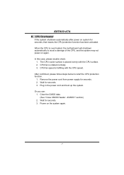
... cord and boot up the system. Power on again. CPU fan is over heated, the motherboard will shutdown automatically to relief the CPU protection function. 1. K8T800-A7A B. Clear the CMOS data. (See "Close CMOS Header: JCMOS1" section) 2. When the CPU is rotated normally. 3. In this case, please double check: 1. Wait for seconds...
... cord and boot up the system. Power on again. CPU fan is over heated, the motherboard will shutdown automatically to relief the CPU protection function. 1. K8T800-A7A B. Clear the CMOS data. (See "Close CMOS Header: JCMOS1" section) 2. When the CPU is rotated normally. 3. In this case, please double check: 1. Wait for seconds...
User Manual
Page 20
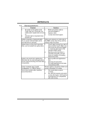
... optical drive. 1. Review system's equipment. Run SETUP program and select correct drive types. Backing up data and applications files. Make sure correct information is impossible. K8T800-A7A 4.3 TROUBLESHOOTING Problem Solution 1. inside power supply does not turn on both ends are capable of the DIMM, press down at all 1. No power to disk...
... optical drive. 1. Review system's equipment. Run SETUP program and select correct drive types. Backing up data and applications files. Make sure correct information is impossible. K8T800-A7A 4.3 TROUBLESHOOTING Problem Solution 1. inside power supply does not turn on both ends are capable of the DIMM, press down at all 1. No power to disk...

User Manual
Page 21
K8T800-A7A CHAPTER 5: WARPSPEEDER™ 5.1 INTRODUCTION [WarpSpeeder™], a new powerful control utility, features three user-friendly functions including Overclock Manager, Overvoltage Manager, and Hardware Monitor. Also, in ...
K8T800-A7A CHAPTER 5: WARPSPEEDER™ 5.1 INTRODUCTION [WarpSpeeder™], a new powerful control utility, features three user-friendly functions including Overclock Manager, Overvoltage Manager, and Hardware Monitor. Also, in ...

User Manual
Page 22
..., and then the following dialog will change according to install. 2. Please click "Next" button and follow the default procedure to your motherboard on hand. 20 K8T800-A7A 5.3 INSTALLATION 1.
..., and then the following dialog will change according to install. 2. Please click "Next" button and follow the default procedure to your motherboard on hand. 20 K8T800-A7A 5.3 INSTALLATION 1.