

User Manual
Page 1
... that interference will not be changed without first obtaining the vendor's approval in writing. All the brand and product names are designed to radio communications. i K8T800-A7A FCC Information and Copyright This equipment has been tested and found in this user's manual. These limits are trademarks of this publication, in part or...
... that interference will not be changed without first obtaining the vendor's approval in writing. All the brand and product names are designed to radio communications. i K8T800-A7A FCC Information and Copyright This equipment has been tested and found in this user's manual. These limits are trademarks of this publication, in part or...
User Manual
Page 3
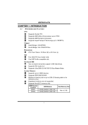
... 2GB. (Following table is 2 GB. 1 Dimensions ATX Form Factor: 19.00cm (W) x 29.31cm (L) Slot Five 32bit PCI bus master slots. Supports DDR-266/333/400. K8T800-A7A CHAPTER 1: INTRODUCTION 1.1 MOTHERBOARD FEATURES CPU Supports Socket 754. On-board IDE Two on-board connectors support 4 IDE disk drives. Supports AMD Athlon 64 processor up...
... 2GB. (Following table is 2 GB. 1 Dimensions ATX Form Factor: 19.00cm (W) x 29.31cm (L) Slot Five 32bit PCI bus master slots. Supports DDR-266/333/400. K8T800-A7A CHAPTER 1: INTRODUCTION 1.1 MOTHERBOARD FEATURES CPU Supports Socket 754. On-board IDE Two on-board connectors support 4 IDE disk drives. Supports AMD Athlon 64 processor up...

User Manual
Page 4
.../s. - Compliant with AC'97 Version 2.3 specification. Supports ACPI, PCI power management. 2 Low Pin Count Interface. Supports RAID 0 and RAID 1 functions. Supports 2 serial ATA (SATA) ports. - K8T800-A7A Super I /O functionality. Supports 10 Mb/s and 100 Mb/s auto-negotiation. Onboard AC'97 Sound CODEC Chip: REALTEK ALC655. Compliant with SATA Version 1.0 specification. 10/100...
.../s. - Compliant with AC'97 Version 2.3 specification. Supports ACPI, PCI power management. 2 Low Pin Count Interface. Supports RAID 0 and RAID 1 functions. Supports 2 serial ATA (SATA) ports. - K8T800-A7A Super I /O functionality. Supports 10 Mb/s and 100 Mb/s auto-negotiation. Onboard AC'97 Sound CODEC Chip: REALTEK ALC655. Compliant with SATA Version 1.0 specification. 10/100...
User Manual
Page 5
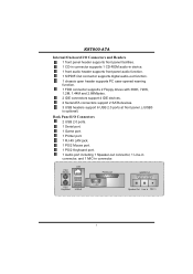
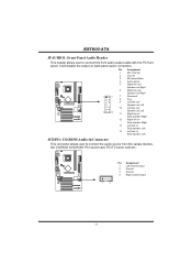
K8T800-A7A Internal On-board I/O Connectors and Headers 1 front panel header supports front panel facilities. 1 CD-in connector supports 1 CD-ROM audio-in device. 1 front audio header ...
K8T800-A7A Internal On-board I/O Connectors and Headers 1 front panel header supports front panel facilities. 1 CD-in connector supports 1 CD-ROM audio-in device. 1 front audio header ...

User Manual
Page 7
The CPU will fit only in the correct orientation. K8T800-A7A CHAPTER 2: HARDWARE INSTALLATION 2.1 INSTALLING CENTRAL PROCESSING UNIT (CPU) Step 1: Pull the lever toward direction A from the socket and then raise the lever up to a 90-degree angle. 90 A Step 2: Look for the cut edge. Connect the CPU FAN power cable to complete the installation. This completes the installation. 5 Step 4: Put the CPU Fan on CPU should point forwards this cut edge on socket, and the gold triangle on the CPU and buckle it. Step 3: Hold the CPU down firmly, and then close the lever to the JCFAN1.
The CPU will fit only in the correct orientation. K8T800-A7A CHAPTER 2: HARDWARE INSTALLATION 2.1 INSTALLING CENTRAL PROCESSING UNIT (CPU) Step 1: Pull the lever toward direction A from the socket and then raise the lever up to a 90-degree angle. 90 A Step 2: Look for the cut edge. Connect the CPU FAN power cable to complete the installation. This completes the installation. 5 Step 4: Put the CPU Fan on CPU should point forwards this cut edge on socket, and the gold triangle on the CPU and buckle it. Step 3: Hold the CPU down firmly, and then close the lever to the JCFAN1.

User Manual
Page 8
... Note: The JCFAN1 and JSFAN1 support 3-pin head connector. Connect the fan cable to the connector while matching the black wire to the fan manufacturer. K8T800-A7A 2.2 FAN HEADERS These fan headers support cooling-fans built in the computer.
... Note: The JCFAN1 and JSFAN1 support 3-pin head connector. Connect the fan cable to the connector while matching the black wire to the fan manufacturer. K8T800-A7A 2.2 FAN HEADERS These fan headers support cooling-fans built in the computer.
User Manual
Page 9
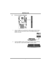
DIMM1 DIMM2 K8T800-A7A 2.3 INSTALLING SYSTEM MEMORY 1. Align a DIMM on the slot such that the notch on the DIMM matches the break on the Slot. 2. Unlock a DIMM slot by pressing the retaining clips outward. Insert the DIMM vertically and firmly into the slot until the retaining chip snap back in place and the DIMM is properly seated. 7
DIMM1 DIMM2 K8T800-A7A 2.3 INSTALLING SYSTEM MEMORY 1. Align a DIMM on the slot such that the notch on the DIMM matches the break on the Slot. 2. Unlock a DIMM slot by pressing the retaining clips outward. Insert the DIMM vertically and firmly into the slot until the retaining chip snap back in place and the DIMM is properly seated. 7

User Manual
Page 10
... Enhanced PCI IDE Controller that supports 360K, 720K, 1.2M, 1.44M and 2.88M floppy disk types. It has two HDD connectors IDE1 (primary) and IDE2 (secondary). K8T800-A7A 2.4 CONNECTORS AND SLOTS FDD1: Floppy Disk Connector The motherboard provides a standard floppy disk connector that provides PIO Mode 0~4, Bus Master, and Ultra DMA 33/66...
... Enhanced PCI IDE Controller that supports 360K, 720K, 1.2M, 1.44M and 2.88M floppy disk types. It has two HDD connectors IDE1 (primary) and IDE2 (secondary). K8T800-A7A 2.4 CONNECTORS AND SLOTS FDD1: Floppy Disk Connector The motherboard provides a standard floppy disk connector that provides PIO Mode 0~4, Bus Master, and Ultra DMA 33/66...

User Manual
Page 11
.... This motherboard supports video cards for PCI slots, but it is equipped with 3D graphics. An AGP card will attach directly to that video card. K8T800-A7A PCI1~PCI5: Peripheral Component Interconnect Slots This motherboard is a bus standard for expansion cards. PCI stands for Peripheral Component Interconnect, and it is designated as...
.... This motherboard supports video cards for PCI slots, but it is equipped with 3D graphics. An AGP card will attach directly to that video card. K8T800-A7A PCI1~PCI5: Peripheral Component Interconnect Slots This motherboard is a bus standard for expansion cards. PCI stands for Peripheral Component Interconnect, and it is designated as...

User Manual
Page 12
... SETTINGS JPANEL1: Front Panel Header This 22-pin connector includes Power-on pins, the jumper is "close", if not, that means the jumper is "open". K8T800-A7A CHAPTER 3: HEADERS & JUMPERS SETUP 3.1 HOW TO SETUP JUMPERS The illustration shows how to connect the PC case's front panel switch functions. When the jumper cap...
... SETTINGS JPANEL1: Front Panel Header This 22-pin connector includes Power-on pins, the jumper is "close", if not, that means the jumper is "open". K8T800-A7A CHAPTER 3: HEADERS & JUMPERS SETUP 3.1 HOW TO SETUP JUMPERS The illustration shows how to connect the PC case's front panel switch functions. When the jumper cap...

User Manual
Page 13
... 3 1 3 1 13 Pin 2-3 close Note: In order to connect additional USB cable on the PC front panel, and also can be placed on Pin 2-3 individually. 11 K8T800-A7A JUSB1/JUSB2/JUSB3: Headers for USB ports at front panel (JUSB1/JUSB2/JUSB3). Pin 2-3 Close: JUSBV1: USB ports at JUSBLAN1 are powered by +5V standby...
... 3 1 3 1 13 Pin 2-3 close Note: In order to connect additional USB cable on the PC front panel, and also can be placed on Pin 2-3 individually. 11 K8T800-A7A JUSB1/JUSB2/JUSB3: Headers for USB ports at front panel (JUSB1/JUSB2/JUSB3). Pin 2-3 Close: JUSBV1: USB ports at JUSBLAN1 are powered by +5V standby...
User Manual
Page 14
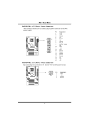
Pin Assignment 1 +3.3V 2 +3.3V 3 Ground 4 +5V 10 20 5 Ground 6 +5V 7 Ground 8 PW_OK 9 Standby Voltage +5V 10 +12V 11 +3.3V 12 -12V 13 Ground 1 11 14 PS_ON 15 Ground 16 Ground 17 Ground 18 -5V 19 +5V 20 +5V JATXPWR2: ATX Power Source Connector By connecting this connector, it will provide +12V to connect 20-pin power connector on the ATX power supply. K8T800-A7A JATXPWR1: ATX Power Source Connector This connector allows user to CPU power circuit. 4 3 Pin Assignment 2 1 1 +12V 2 +12V 3 Ground 4 Ground 12
Pin Assignment 1 +3.3V 2 +3.3V 3 Ground 4 +5V 10 20 5 Ground 6 +5V 7 Ground 8 PW_OK 9 Standby Voltage +5V 10 +12V 11 +3.3V 12 -12V 13 Ground 1 11 14 PS_ON 15 Ground 16 Ground 17 Ground 18 -5V 19 +5V 20 +5V JATXPWR2: ATX Power Source Connector By connecting this connector, it will provide +12V to connect 20-pin power connector on the ATX power supply. K8T800-A7A JATXPWR1: ATX Power Source Connector This connector allows user to CPU power circuit. 4 3 Pin Assignment 2 1 1 +12V 2 +12V 3 Ground 4 Ground 12
User Manual
Page 15
It will disable the output on back panel audio connectors. K8T800-A7A JFAUDIO1: Front Panel Audio Header This header allows user to connect the audio source from the variaty devices, like CD-ROM, DVD-ROM, PCI sound ...
It will disable the output on back panel audio connectors. K8T800-A7A JFAUDIO1: Front Panel Audio Header This header allows user to connect the audio source from the variaty devices, like CD-ROM, DVD-ROM, PCI sound ...

User Manual
Page 16
... setting and the CMOS data, please carefully follow the procedures to avoid damaging the motherboard. 1 3 Pin 1-2 Close: Normal Operation (default). 1 1 3 3 Pin 2-3 Close: Clear CMOS data. K8T800-A7A JCMOS1: Clear CMOS Header By placing the jumper on pin2-3, it will record to the CMOS and show the message on the AC. 6. Remove AC...
... setting and the CMOS data, please carefully follow the procedures to avoid damaging the motherboard. 1 3 Pin 1-2 Close: Normal Operation (default). 1 1 3 3 Pin 2-3 Close: Clear CMOS data. K8T800-A7A JCMOS1: Clear CMOS Header By placing the jumper on pin2-3, it will record to the CMOS and show the message on the AC. 6. Remove AC...
User Manual
Page 17
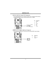
K8T800-A7A JSATA1~JSATA2: Serial ATA Connectors The motherboard has a PCI to SATA Controller with 2 channels SATA interface, it satisfies the SATA 1.0 spec and with transfer rate of 1.5GB/s. 741 JSATA1 Pin Assignment 1 Ground 2 TX+ 3 TX4 Ground 5 RX6 RX+ 7 Ground JSPDIF_OUT1: Digital Audio-out Connector This connector allows user to connect the PCI bracket SPDIF output header. 1 3 Pin Assignment 1 +5V 2 SPDIF_OUT 3 Ground 15
K8T800-A7A JSATA1~JSATA2: Serial ATA Connectors The motherboard has a PCI to SATA Controller with 2 channels SATA interface, it satisfies the SATA 1.0 spec and with transfer rate of 1.5GB/s. 741 JSATA1 Pin Assignment 1 Ground 2 TX+ 3 TX4 Ground 5 RX6 RX+ 7 Ground JSPDIF_OUT1: Digital Audio-out Connector This connector allows user to connect the PCI bracket SPDIF output header. 1 3 Pin Assignment 1 +5V 2 SPDIF_OUT 3 Ground 15

User Manual
Page 18
K8T800-A7A CHAPTER 4: USEFUL HELP 4.1 AWARD BIOS BEEP CODE Beep Sound One long beep followed by virus, the Boot-Block function will ...The BIOS has been recovered and will update BIOS automatically and restart. 9. Confirm motherboard model and download the respectively BIOS from the Biostar website: www.biostar.com.tw 3. In this Case, please follow the procedure below to DOS prompt. 7. BIOS Update After you fail to update ... 1. Copy "AWDFLASH.exe" and respectively BIOS into floppy drive and press Enter. 6. Download the Flash Utility "AWDFLASH.exe" from Biostar website. 4.
K8T800-A7A CHAPTER 4: USEFUL HELP 4.1 AWARD BIOS BEEP CODE Beep Sound One long beep followed by virus, the Boot-Block function will ...The BIOS has been recovered and will update BIOS automatically and restart. 9. Confirm motherboard model and download the respectively BIOS from the Biostar website: www.biostar.com.tw 3. In this Case, please follow the procedure below to DOS prompt. 7. BIOS Update After you fail to update ... 1. Copy "AWDFLASH.exe" and respectively BIOS into floppy drive and press Enter. 6. Download the Flash Utility "AWDFLASH.exe" from Biostar website. 4.
User Manual
Page 19
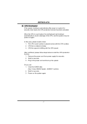
... function. 1. CPU fan speed is placed evenly with the CPU speed. CPU Overheated If the system shutdown automatically after power on the system again. 17 K8T800-A7A B. When the CPU is rotated normally. 3. Power on system for seconds. 3.
... function. 1. CPU fan speed is placed evenly with the CPU speed. CPU Overheated If the system shutdown automatically after power on the system again. 17 K8T800-A7A B. When the CPU is rotated normally. 3. Power on system for seconds. 3.
User Manual
Page 20
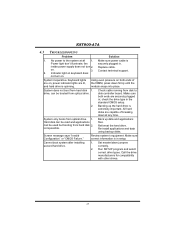
... not turn 2. Hard disk can be read and applications can be used but booting from hard disk 2. Back up the hard drive is extremely important. K8T800-A7A 4.3 TROUBLESHOOTING Problem Solution 1. drive, can be booted from disk to the system at any time. Review system's equipment. No power to disk controller board. Contact...
... not turn 2. Hard disk can be read and applications can be used but booting from hard disk 2. Back up the hard drive is extremely important. K8T800-A7A 4.3 TROUBLESHOOTING Problem Solution 1. drive, can be booted from disk to the system at any time. Review system's equipment. No power to disk controller board. Contact...

User Manual
Page 21
... hang, [WarpSpeeder™] technology assures the system stability by automatically rebooting the computer and then restart to power up CPU core voltage and Memory voltage. K8T800-A7A CHAPTER 5: WARPSPEEDER™ 5.1 INTRODUCTION [WarpSpeeder™], a new powerful control utility, features three user-friendly functions including Overclock Manager, Overvoltage Manager, and Hardware Monitor. If you...
... hang, [WarpSpeeder™] technology assures the system stability by automatically rebooting the computer and then restart to power up CPU core voltage and Memory voltage. K8T800-A7A CHAPTER 5: WARPSPEEDER™ 5.1 INTRODUCTION [WarpSpeeder™], a new powerful control utility, features three user-friendly functions including Overclock Manager, Overvoltage Manager, and Hardware Monitor. If you...

User Manual
Page 22
.... Usage: The following dialog will be automatically and immediately launched after you see the following dialog in this user manual will change according to install. 2. K8T800-A7A 5.3 INSTALLATION 1. Please click "Next" button and follow the default procedure to your motherboard on hand. 20
.... Usage: The following dialog will be automatically and immediately launched after you see the following dialog in this user manual will change according to install. 2. K8T800-A7A 5.3 INSTALLATION 1. Please click "Next" button and follow the default procedure to your motherboard on hand. 20