CR800 and CR850 Measurement and Control Systems
Page 201
... smart sensors that deliver measurement data through serial data protocols. Read More! See Telecommunications and Data Retrieval (p. 332) for display. #If LoggerType = CR3000 SelectedSpeed = "CR3000 running at " & Speed & " intervals." #ElseIf LoggerTypes = CR1000 SelectedSpeed = "CR1000 running at " & Speed & " intervals." #ElseIf LoggerType = CR800 SelectedSpeed = "CR800 running at " & Speed & " intervals." #Else SelectedSpeed = "Unknown Logger " & Speed & " intervals." #EndIf 'Open the...
... smart sensors that deliver measurement data through serial data protocols. Read More! See Telecommunications and Data Retrieval (p. 332) for display. #If LoggerType = CR3000 SelectedSpeed = "CR3000 running at " & Speed & " intervals." #ElseIf LoggerTypes = CR1000 SelectedSpeed = "CR1000 running at " & Speed & " intervals." #ElseIf LoggerType = CR800 SelectedSpeed = "CR800 running at " & Speed & " intervals." #Else SelectedSpeed = "Unknown Logger " & Speed & " intervals." #EndIf 'Open the...
CR1000 Measurement and Control System
Page 9
... 7.5.3.2 External Signal Conditioner 90 7.5.4 Ground Looping in Ionic Measurements 91 7.6 CR1000 Configuration 92 7.6.1 Device Configuration Utility 92 7.6.2 Sending the Operating System 93...Memory 96 7.6.3 Settings 96 7.6.3.1 Settings via DevConfig 96 7.6.3.1.1 Deployment Tab 98 7.6.3.1.2 Logger Control Tab 102 7.6.3.2 Settings via CRBasic 103 7.6.3.3 Durable Settings 103 7.6.3.3.1 "Include... 109 7.7.1.2.1 Inserting Comments into Program 110 7.7.2 Sending Programs 110 7.7.2.1 Preserving Data at Program Send 110 7.7.3 Syntax 112 7.7.3.1 Numerical Formats 112 7.7.3.2 Structure ...
... 7.5.3.2 External Signal Conditioner 90 7.5.4 Ground Looping in Ionic Measurements 91 7.6 CR1000 Configuration 92 7.6.1 Device Configuration Utility 92 7.6.2 Sending the Operating System 93...Memory 96 7.6.3 Settings 96 7.6.3.1 Settings via DevConfig 96 7.6.3.1.1 Deployment Tab 98 7.6.3.1.2 Logger Control Tab 102 7.6.3.2 Settings via CRBasic 103 7.6.3.3 Durable Settings 103 7.6.3.3.1 "Include... 109 7.7.1.2.1 Inserting Comments into Program 110 7.7.2 Sending Programs 110 7.7.2.1 Preserving Data at Program Send 110 7.7.3 Syntax 112 7.7.3.1 Numerical Formats 112 7.7.3.2 Structure ...

CR1000 Measurement and Control System
Page 19
...Data tab 53 Figure 23: PC200W View data utility 54 Figure 24: PC200W View data table 55 Figure 25: PC200W View line graph 55 Figure 26: Features of a data-acquisition system 58 Figure 27: CR1000KD... confirming OS download 95 Figure 37: DevConfig Settings Editor 97 Figure 38: Summary of CR1000 configuration 98 Figure 39: DevConfig Deployment tab 99 Figure 40: DevConfig Deployment | ComPorts ...Settings tab 101 Figure 41: DevConfig Deployment | Advanced tab 102 Figure 42: DevConfig Logger Control tab 103 Figure 43: "Include File" settings via DevConfig 104 Figure 44: "Include ...
...Data tab 53 Figure 23: PC200W View data utility 54 Figure 24: PC200W View data table 55 Figure 25: PC200W View line graph 55 Figure 26: Features of a data-acquisition system 58 Figure 27: CR1000KD... confirming OS download 95 Figure 37: DevConfig Settings Editor 97 Figure 38: Summary of CR1000 configuration 98 Figure 39: DevConfig Deployment tab 99 Figure 40: DevConfig Deployment | ComPorts ...Settings tab 101 Figure 41: DevConfig Deployment | Advanced tab 102 Figure 42: DevConfig Logger Control tab 103 Figure 43: "Include File" settings via DevConfig 104 Figure 44: "Include ...
CR1000 Measurement and Control System
Page 69
...Campbell Scientific support software, telecommunication peripherals, and other dataloggers via RS-232, CS I/O, or digital I /O port, over distances up to datalogger communications - See PakBus Overview (p. 351). The CR1000 communicates with a network. no extra hardware --a CR1000 can talk to another logger...) software. 5.1.9.2 Modbus Read More! Advantages of communications and networking options available to consolidate all data into one CR1000. • Routing - the CR1000 can be used as a router, passing on available communications devices. 5.1.9.1 PakBus Read More! ...
...Campbell Scientific support software, telecommunication peripherals, and other dataloggers via RS-232, CS I/O, or digital I /O port, over distances up to datalogger communications - See PakBus Overview (p. 351). The CR1000 communicates with a network. no extra hardware --a CR1000 can talk to another logger...) software. 5.1.9.2 Modbus Read More! Advantages of communications and networking options available to consolidate all data into one CR1000. • Routing - the CR1000 can be used as a router, passing on available communications devices. 5.1.9.1 PakBus Read More! ...
CR1000 Measurement and Control System
Page 103
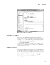
... via CRBasic Some variables in any data table. Entries can be changed remotely over a telecommunications link either directly or as by replacing it with the CR1000, the remedy for which may be a site visit. 7.6.3.3 Durable Settings Many CR1000 settings can be requested or set... during program execution using CRBasic commands SetStatus() and SetSecurity(). For example, to set a variable, x, equal to the Status table entry, as can be requested or set by a switched 12-Vdc (SW12) channel. Installation Figure 42: DevConfig Logger Control...
... via CRBasic Some variables in any data table. Entries can be changed remotely over a telecommunications link either directly or as by replacing it with the CR1000, the remedy for which may be a site visit. 7.6.3.3 Durable Settings Many CR1000 settings can be requested or set... during program execution using CRBasic commands SetStatus() and SetSecurity(). For example, to set a variable, x, equal to the Status table entry, as can be requested or set by a switched 12-Vdc (SW12) channel. Installation Figure 42: DevConfig Logger Control...
CR1000 Measurement and Control System
Page 176
...data. Response: 500201 (atttnn indicates address 5, data ready in 2 seconds, will report 10 values). The datalogger scan rate should be returned when one or more subsequent D! A measurement request is then sent again so data...time of measurement and time of data collection does not compromise data integrity. Response: 500410 (atttnn, indicates address 5, data ready in seconds, until measurement data are issued. v = 7 ... up the requested data on the next scan. Example: Command: 5M7! Start Concurrent Measurement Command (aC!) Concurrent measurement allows the CR1000 to be set...
...data. Response: 500201 (atttnn indicates address 5, data ready in 2 seconds, will report 10 values). The datalogger scan rate should be returned when one or more subsequent D! A measurement request is then sent again so data...time of measurement and time of data collection does not compromise data integrity. Response: 500410 (atttnn, indicates address 5, data ready in seconds, until measurement data are issued. v = 7 ... up the requested data on the next scan. Example: Command: 5M7! Start Concurrent Measurement Command (aC!) Concurrent measurement allows the CR1000 to be set...
CR1000 Measurement and Control System
Page 177
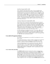
...example, when the SDI12Recorder() instruction 177 Responses to R commands are formatted like responses to obtain data. need not be preceded by the CRC. 7.8.3.2 SDI-12 Programmed Modes The CR1000 can be read directly with subsequent aDv! through aR4!. Enter terminal mode as described in transparent... expected number of the response is that R commands do not require a Start Measurement (M) command. command, the data logger issues aD1!, aD2!, etc., until CR1000> prompt appears. In transparent mode, a user does likewise. They can be programmed to initiate a measurement and get...
...example, when the SDI12Recorder() instruction 177 Responses to R commands are formatted like responses to obtain data. need not be preceded by the CRC. 7.8.3.2 SDI-12 Programmed Modes The CR1000 can be read directly with subsequent aDv! through aR4!. Enter terminal mode as described in transparent... expected number of the response is that R commands do not require a Start Measurement (M) command. command, the data logger issues aD1!, aD2!, etc., until CR1000> prompt appears. In transparent mode, a user does likewise. They can be programmed to initiate a measurement and get...
CR1000 Measurement and Control System
Page 198
...- 1 'Count down by 1 If CountDown Installation 'Measure Two Thermocouples TCDiff(TCTemp(),2,mV2500C,1,TypeT,RefTemp,True,0,250,1.0,0) CallTable TempC 'Call data table 'Menu Item "Make Notes" Support Code If CycleNotes = "Accept" Then CallTable Notes CycleNotes = "Accepted" Delay(1,500,mSec) SelectNote =... "" EnterNote = "" CycleNotes = "??????" EndIf 'Write data to Notes data table 'Write "Accepted" after written 'Pause so user can read "Accepted" 'Clear pick list note 'Clear free entry note 'Write ...
...- 1 'Count down by 1 If CountDown Installation 'Measure Two Thermocouples TCDiff(TCTemp(),2,mV2500C,1,TypeT,RefTemp,True,0,250,1.0,0) CallTable TempC 'Call data table 'Menu Item "Make Notes" Support Code If CycleNotes = "Accept" Then CallTable Notes CycleNotes = "Accepted" Delay(1,500,mSec) SelectNote =... "" EnterNote = "" CycleNotes = "??????" EndIf 'Write data to Notes data table 'Write "Accepted" after written 'Pause so user can read "Accepted" 'Clear pick list note 'Clear free entry note 'Write ...
CR1000 Measurement and Control System
Page 200
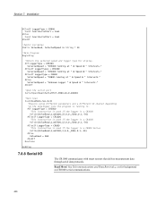
...,1,mV2500,12,0,0,_50Hz,0.1,-30) #ElseIf LoggerType = CR800 'This instruction is used if the logger is a CR800 Series VoltSe(ValueRead,1,mV2500,3,0,0,_50Hz,0.1,-30) #Else ValueRead = NaN #EndIf NextScan EndProg 7.8.8 Serial I/O The CR1000 communicates with smart sensors that deliver measurement data through serial data protocols. Installation #ElseIf LoggerType = CR800 Const SourcSerialPort = Com1 #Else Const SourcSerialPort = Com1...
...,1,mV2500,12,0,0,_50Hz,0.1,-30) #ElseIf LoggerType = CR800 'This instruction is used if the logger is a CR800 Series VoltSe(ValueRead,1,mV2500,3,0,0,_50Hz,0.1,-30) #Else ValueRead = NaN #EndIf NextScan EndProg 7.8.8 Serial I/O The CR1000 communicates with smart sensors that deliver measurement data through serial data protocols. Installation #ElseIf LoggerType = CR800 Const SourcSerialPort = Com1 #Else Const SourcSerialPort = Com1...
CR1000 Measurement and Control System
Page 220
...CHR(01) + "CWGT0" + CHR(03),8) SerialOutBlock(COMRS232, CHR(0),1) SerialOutBlock(COMRS232, CHR(13) + CHR(10),2) Q: Please explain and summarize when the CR1000 powers the RS-232 port. Does the SerialOpen() instruction cause other power cycles? A: The RS-232 port is left on " setting. Under normal operation the... instruction, which lets you send null characters, as sending a beacon, it can I get the logger to send this reason SerialOpen() leaves the interface powered up the interface, send the data, and return to a received packet, such as shown below. After receiving input, there is a ...
...CHR(01) + "CWGT0" + CHR(03),8) SerialOutBlock(COMRS232, CHR(0),1) SerialOutBlock(COMRS232, CHR(13) + CHR(10),2) Q: Please explain and summarize when the CR1000 powers the RS-232 port. Does the SerialOpen() instruction cause other power cycles? A: The RS-232 port is left on " setting. Under normal operation the... instruction, which lets you send null characters, as sending a beacon, it can I get the logger to send this reason SerialOpen() leaves the interface powered up the interface, send the data, and return to a received packet, such as shown below. After receiving input, there is a ...

CR1000 Measurement and Control System
Page 326
... ClockReport() can catch the rising edge of a digital pulse from and send data to within 10 ms. The NTP server could be synchronized to the CR1000 326 CR1000s built since October of 2008 (serial numbers ≥ 20409) can be another logger or any NTP server (such as to keep clocks within ≈200 µ...
... ClockReport() can catch the rising edge of a digital pulse from and send data to within 10 ms. The NTP server could be synchronized to the CR1000 326 CR1000s built since October of 2008 (serial numbers ≥ 20409) can be another logger or any NTP server (such as to keep clocks within ≈200 µ...
CR1000 Measurement and Control System
Page 425
... on power-up, the CR1000 should be repaired by a qualified technician. Removing the offending signal and powering up , the problem is Indicates a problem with Scan 1 SlowSequence scan rate is corrected. If no invalid external signals are present and / or self-calibration fails again on power-up the logger will skip scans if...
... on power-up, the CR1000 should be repaired by a qualified technician. Removing the offending signal and powering up , the problem is Indicates a problem with Scan 1 SlowSequence scan rate is corrected. If no invalid external signals are present and / or self-calibration fails again on power-up the logger will skip scans if...
CR1000 Measurement and Control System
Page 428
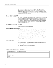
... = NAN Then WDFlag = False Else WDFlag = True EndIf 428 Floating measurements tend to Filter Data (p. 431). 10.3.4.1 Measurements and NAN A NAN indicates an invalid measurement. 10.3.4.1.1 Voltage Measurements The CR1000 has the following user-selectable voltage ranges: ±5000 mV, ±2500 mV, ±... the resulting measured voltage often remains near the voltage of the logger, but it can be a useful tool for all scans, then try experimenting with the disable variable (DisableVar) in output processing (data storage) instructions as shown in CRBasic example Using NAN in Expressions...
... = NAN Then WDFlag = False Else WDFlag = True EndIf 428 Floating measurements tend to Filter Data (p. 431). 10.3.4.1 Measurements and NAN A NAN indicates an invalid measurement. 10.3.4.1.1 Voltage Measurements The CR1000 has the following user-selectable voltage ranges: ±5000 mV, ±2500 mV, ±... the resulting measured voltage often remains near the voltage of the logger, but it can be a useful tool for all scans, then try experimenting with the disable variable (DisableVar) in output processing (data storage) instructions as shown in CRBasic example Using NAN in Expressions...
CR1000 Measurement and Control System
Page 443
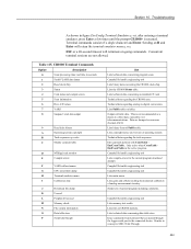
...Terminal emulator menu I Calibration data J Download file dump K Unused L Peripheral bus read M Memory check N File system information O Data table sizes P Serial talk through the logger serial port to SDI12 ...Campbell Scientific engineering tool Lists compile errors for the current program download attempt. Campbell Scientific engineering tool Lists memory-test results Lists files in CR1000 memory. Campbell Scientific engineering tool Campbell Scientific engineering tool Lists main menu. Section 10. Campbell Scientific engineering tool Lists binary data concerning the CR1000...
...Terminal emulator menu I Calibration data J Download file dump K Unused L Peripheral bus read M Memory check N File system information O Data table sizes P Serial talk through the logger serial port to SDI12 ...Campbell Scientific engineering tool Lists compile errors for the current program download attempt. Campbell Scientific engineering tool Lists memory-test results Lists files in CR1000 memory. Campbell Scientific engineering tool Campbell Scientific engineering tool Lists main menu. Section 10. Campbell Scientific engineering tool Lists binary data concerning the CR1000...
CR1000 Measurement and Control System
Page 538
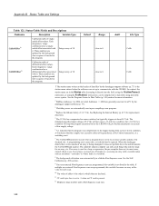
Integer array of data files by the datalogger support software (p. 77) is the station name entered when the software was set... typing it . In contrast, the station name set up to communicate with the CR1000. Integer array of 18 CalDiffOffset19 Calibration table of singleended offset values. See the Program Access to Data Tables (p. 148) section for a PC by the background slow sequence if needed in...with it directly into the field, using the StationName() instruction, or using the SetStatus() instruction), can be sampled into a data table using data table access syntax.
Integer array of data files by the datalogger support software (p. 77) is the station name entered when the software was set... typing it . In contrast, the station name set up to communicate with the CR1000. Integer array of 18 CalDiffOffset19 Calibration table of singleended offset values. See the Program Access to Data Tables (p. 148) section for a PC by the background slow sequence if needed in...with it directly into the field, using the StationName() instruction, or using the SetStatus() instruction), can be sampled into a data table using data table access syntax.
CR1000 Measurement and Control System
Page 545
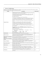
...data collection packet. 1000 RS232 Always On Controls whether the RS-232 port will remain active even when communication is not affected by the datalogger when it starts are as zero, the address, net mask, and gateway are accessed through the Campbell Scientific... this setting follows: include-setting := device-name ":" file-name "." CR1000 Settings Settings are configured automatically using DHCP. Setting Description Default Entry Include ...Mask Specifies the subnet mask for the Ethernet interface. If the logger is starting from power-up to Yes RS232 Hardware Handshaking If ...
...data collection packet. 1000 RS232 Always On Controls whether the RS-232 port will remain active even when communication is not affected by the datalogger when it starts are as zero, the address, net mask, and gateway are accessed through the Campbell Scientific... this setting follows: include-setting := device-name ":" file-name "." CR1000 Settings Settings are configured automatically using DHCP. Setting Description Default Entry Include ...Mask Specifies the subnet mask for the Ethernet interface. If the logger is starting from power-up to Yes RS232 Hardware Handshaking If ...
CR1000 Measurement and Control System
Page 550
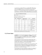
...powered down . Table 124. PIN DCE Function Logger Function I/O Description 1 DCD DTR (tied to pin 6) O* Data terminal ready 2 TXD TXD O Asynchronous data transmit 3 RXD RXD I Asynchronous data receive 4 DTR N/A X* Not connected 5 GND GND GND Ground 6 DSR DTR O* Data terminal ready 7 CTS CTS I Clear to send...DCE-naming notation. Upon receiving input there is used after SerialOpen(), the port is to accommodate a connection to the CR1000 DCE device. C.2.2 Power States The RS-232 port is powered under the following table describes RS-232 pin function with...
...powered down . Table 124. PIN DCE Function Logger Function I/O Description 1 DCD DTR (tied to pin 6) O* Data terminal ready 2 TXD TXD O Asynchronous data transmit 3 RXD RXD I Asynchronous data receive 4 DTR N/A X* Not connected 5 GND GND GND Ground 6 DSR DTR O* Data terminal ready 7 CTS CTS I Clear to send...DCE-naming notation. Upon receiving input there is used after SerialOpen(), the port is to accommodate a connection to the CR1000 DCE device. C.2.2 Power States The RS-232 port is powered under the following table describes RS-232 pin function with...