Illustrated Parts & Service Map Pro 6305 Business PC Microtower
Page 2
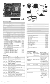
...Messages Screen Message Probable Cause Recommended Action 101-Option ROM Error 1. System unable to fail. Remove suspected card, reboot 3. Clear CMOS memory, reboot 4. Remove expansion boards. 3. Run Setup (F10). 2. Remove DIMMs singularly and reboot to boot Bad option card Current ... not optimized each channel has the same amount of memory. 301-, 304-Keyboard error Keyboard failure. Detects Imminent Failure 1. Determine if hard drive is unable to isolate faulty DIMM. 4. Apply hard drive firmware patch if applicable. 3. HP Compaq Pro 6305, MT 706895-003 page 2
...Messages Screen Message Probable Cause Recommended Action 101-Option ROM Error 1. System unable to fail. Remove suspected card, reboot 3. Clear CMOS memory, reboot 4. Remove expansion boards. 3. Run Setup (F10). 2. Remove DIMMs singularly and reboot to boot Bad option card Current ... not optimized each channel has the same amount of memory. 301-, 304-Keyboard error Keyboard failure. Detects Imminent Failure 1. Determine if hard drive is unable to isolate faulty DIMM. 4. Apply hard drive firmware patch if applicable. 3. HP Compaq Pro 6305, MT 706895-003 page 2
Illustrated Parts & Service Map Pro 6305 Business PC Microtower
Page 3
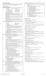
... Server Mode Smart Cover - To establish new passwords, repeat steps 1 through 4, replace the password jumper on or restart the computer. HP Compaq Pro 6305, MT 706895-003 page 3 System Setup and Boot Access the Setup Utility during computer boot by the OS. Allows you to enable/disable...8226; Product name • SKU number (some models) • Processor type/speed/stepping • Cache size (L1/L2/L3) • Installed memory size/speed/ch • Integrated MAC Address • System BIOS • Chassis serial number • Asset tracking number • ME firmware version &#...
... Server Mode Smart Cover - To establish new passwords, repeat steps 1 through 4, replace the password jumper on or restart the computer. HP Compaq Pro 6305, MT 706895-003 page 3 System Setup and Boot Access the Setup Utility during computer boot by the OS. Allows you to enable/disable...8226; Product name • SKU number (some models) • Processor type/speed/stepping • Cache size (L1/L2/L3) • Installed memory size/speed/ch • Integrated MAC Address • System BIOS • Chassis serial number • Asset tracking number • ME firmware version &#...
Illustrated Parts & Service Map Pro 6305 Business PC Microtower
Page 4
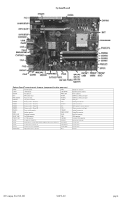
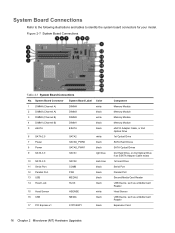
... header SATA SPWR1 CHFAN Fan connector PWR CMD BAT RTC battery socket MEDIA PROCESSOR Processor socket MEDIA2 PWRCPU CPU power connector COMB DIMM4 Memory socket - Channel A IN/OUT DIMM2 Memory socket - Channel B VGA PB/LED Power switch connector CHFAN2 SPKR Speaker connector DISPLAYPORT FRNT AUD Front panel connector HLCK FRONT USB2... connector Hood lock connector USB connectors Network+USB connectors Hood sensor connector PCIe X1 slot PCIe X16 slot PCIe X16 slot PCI slot HP Compaq Pro 6305, MT 706895-003 page 4 Channel B PS2 DIMM1 Memory socket -
... header SATA SPWR1 CHFAN Fan connector PWR CMD BAT RTC battery socket MEDIA PROCESSOR Processor socket MEDIA2 PWRCPU CPU power connector COMB DIMM4 Memory socket - Channel A IN/OUT DIMM2 Memory socket - Channel B VGA PB/LED Power switch connector CHFAN2 SPKR Speaker connector DISPLAYPORT FRNT AUD Front panel connector HLCK FRONT USB2... connector Hood lock connector USB connectors Network+USB connectors Hood sensor connector PCIe X1 slot PCIe X16 slot PCIe X16 slot PCI slot HP Compaq Pro 6305, MT 706895-003 page 4 Channel B PS2 DIMM1 Memory socket -
Hardware Reference Guide
Page 5
... the Computer Access Panel 13 Removing the Front Bezel ...14 Removing Bezel Blanks ...15 Replacing the Front Bezel ...15 System Board Connections ...16 Installing Additional Memory ...17 DIMMs ...17 DDR3-SDRAM DIMMs ...17 Populating DIMM Sockets 18 Installing DIMMs ...18 Removing or Installing an Expansion Card 20 Drive Positions ...24 Installing...
... the Computer Access Panel 13 Removing the Front Bezel ...14 Removing Bezel Blanks ...15 Replacing the Front Bezel ...15 System Board Connections ...16 Installing Additional Memory ...17 DIMMs ...17 DDR3-SDRAM DIMMs ...17 Populating DIMM Sockets 18 Installing DIMMs ...18 Removing or Installing an Expansion Card 20 Drive Positions ...24 Installing...

Hardware Reference Guide
Page 6
... Front Bezel ...47 Removing Bezel Blanks ...48 Replacing the Front Bezel ...48 Changing from Desktop to Tower Configuration 49 System Board Connections ...50 Installing Additional Memory ...51 DIMMs ...51 DDR3-SDRAM DIMMs ...51 Populating DIMM Sockets 51 Installing DIMMs ...52 Removing or Installing an Expansion Card 55 Drive Positions ...59 Installing...
... Front Bezel ...47 Removing Bezel Blanks ...48 Replacing the Front Bezel ...48 Changing from Desktop to Tower Configuration 49 System Board Connections ...50 Installing Additional Memory ...51 DIMMs ...51 DDR3-SDRAM DIMMs ...51 Populating DIMM Sockets 51 Installing DIMMs ...52 Removing or Installing an Expansion Card 55 Drive Positions ...59 Installing...
Hardware Reference Guide
Page 14
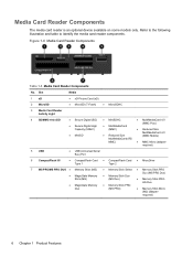
... Type 1 ● CompactFlash Card Type 2 ● MicroDrive 7 MS PRO/MS PRO DUO ● Memory Stick (MS) ● Memory Stick Select ● Memory Stick PRO ● MagicGate Memory ● Memory Stick Duo Duo (MS PRO Duo) Stick (MG) (MS Duo) ● Memory Stick PRO- ● MagicGate Memory ● Memory Stick PRO HG Duo Duo (MS PRO) ● Memory Stick Micro (M2) (adapter required) 6 Chapter 1 Product Features Refer...
... Type 1 ● CompactFlash Card Type 2 ● MicroDrive 7 MS PRO/MS PRO DUO ● Memory Stick (MS) ● Memory Stick Select ● Memory Stick PRO ● MagicGate Memory ● Memory Stick Duo Duo (MS PRO Duo) Stick (MG) (MS Duo) ● Memory Stick PRO- ● MagicGate Memory ● Memory Stick PRO HG Duo Duo (MS PRO) ● Memory Stick Micro (M2) (adapter required) 6 Chapter 1 Product Features Refer...
Hardware Reference Guide
Page 24
... MEDIA2 HLCK dark blue black black black black 15 Hood Sensor 16 USB HSENSE MEDIA white black 17 PCI Express x1 X1PCIEXP1 black Component Memory Module Memory Module Memory Module Memory Module eSATA Adapter Cable, or 2nd Optical Drive 1st Optical Drive SATA Hard Drives SATA Optical Drives 2nd Hard Drive, or 2nd Optical...
... MEDIA2 HLCK dark blue black black black black 15 Hood Sensor 16 USB HSENSE MEDIA white black 17 PCI Express x1 X1PCIEXP1 black Component Memory Module Memory Module Memory Module Memory Module eSATA Adapter Cable, or 2nd Optical Drive 1st Optical Drive SATA Hard Drives SATA Optical Drives 2nd Hard Drive, or 2nd Optical...
Hardware Reference Guide
Page 25
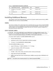
... a x4 19 PCI Express x16 X16PCIEXP 20 PCI PCI1 Color white black white Component Expansion Card Expansion Card Expansion Card Installing Additional Memory The computer comes with up to the DIMM or invoke system malfunction. Table 2-1 System Board Connections (continued) No. System Board...the mandatory JEDEC SPD information In addition, the computer supports: ● 512-Mbit, 1-Gbit, 2-Gbit, 4-Gbit, and 8-Gbit non-ECC memory technologies ● single-sided and double-sided DIMMs ● DIMMs constructed with at least one preinstalled DIMM. DIMMs constructed with x4 SDRAM are ...
... a x4 19 PCI Express x16 X16PCIEXP 20 PCI PCI1 Color white black white Component Expansion Card Expansion Card Expansion Card Installing Additional Memory The computer comes with up to the DIMM or invoke system malfunction. Table 2-1 System Board Connections (continued) No. System Board...the mandatory JEDEC SPD information In addition, the computer supports: ● 512-Mbit, 1-Gbit, 2-Gbit, 4-Gbit, and 8-Gbit non-ECC memory technologies ● single-sided and double-sided DIMMs ● DIMMs constructed with at least one preinstalled DIMM. DIMMs constructed with x4 SDRAM are ...
Hardware Reference Guide
Page 26
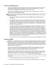
...any security devices that the largest amount of static electricity by the slowest DIMM in the system. NOTE: Single channel and unbalanced dual channel memory configurations will result in inferior graphics performance. ● The system will operate in single channel mode if the DIMM sockets are populated in .... Remove all removable media, such as single channel. ● In any of the power-on state, voltage is always supplied to the memory modules as long as the computer is plugged into an active AC outlet. Populating DIMM Sockets There are four DIMM sockets on the system board...
...any security devices that the largest amount of static electricity by the slowest DIMM in the system. NOTE: Single channel and unbalanced dual channel memory configurations will result in inferior graphics performance. ● The system will operate in single channel mode if the DIMM sockets are populated in .... Remove all removable media, such as single channel. ● In any of the power-on state, voltage is always supplied to the memory modules as long as the computer is plugged into an active AC outlet. Populating DIMM Sockets There are four DIMM sockets on the system board...
Hardware Reference Guide
Page 27
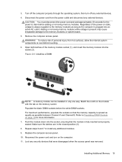
...Reconnect the power cord and turn off any external devices. Disconnect the power cord from hot surfaces, allow the internal system components to the memory modules as long as possible between Channel A and Channel B. Open both latches of the power-on the computer. 11. For maximum ...Replace the computer access panel. 10. Lock any additional modules. 9. Push the module down into the socket (2). Repeat steps 6 and 7 to the memory modules or system board. 5. 3. Refer to drain before the white DIMM sockets. CAUTION: You must disconnect the power cord and wait approximately 30 ...
...Reconnect the power cord and turn off any external devices. Disconnect the power cord from hot surfaces, allow the internal system components to the memory modules as long as possible between Channel A and Channel B. Open both latches of the power-on the computer. 11. For maximum ...Replace the computer access panel. 10. Lock any additional modules. 9. Push the module down into the socket (2). Repeat steps 6 and 7 to the memory modules or system board. 5. 3. Refer to drain before the white DIMM sockets. CAUTION: You must disconnect the power cord and wait approximately 30 ...
Hardware Reference Guide
Page 28
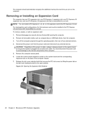
... and disconnect any external devices. Remove all removable media, such as the system is downshifted to a x4 slot. The computer should automatically recognize the additional memory the next time you turn off the computer properly through the operating system, then turn on the computer. Removing or Installing an Expansion Card The...
... and disconnect any external devices. Remove all removable media, such as the system is downshifted to a x4 slot. The computer should automatically recognize the additional memory the next time you turn off the computer properly through the operating system, then turn on the computer. Removing or Installing an Expansion Card The...

Hardware Reference Guide
Page 58
... identify the system board connectors for your model. System Board Connections Refer to the following illustration and table to a x4 black white Component Memory Module Memory Module Memory Module Memory Module eSATA Adapter Cable 1st Optical Drive (unused) SATA Optical and Hard Drives 2nd Hard Drive 1st Hard Drive Serial Port Parallel Port Second...
... identify the system board connectors for your model. System Board Connections Refer to the following illustration and table to a x4 black white Component Memory Module Memory Module Memory Module Memory Module eSATA Adapter Cable 1st Optical Drive (unused) SATA Optical and Hard Drives 2nd Hard Drive 1st Hard Drive Serial Port Parallel Port Second...

Hardware Reference Guide
Page 59
System Board Connector System Board Label 19 PCI Express x16 X16PCIEXP 20 PCI PCI1 Color black white Component Expansion Card Expansion Card Installing Additional Memory The computer comes with x8 and x16 DDR devices; Table 3-1 System Board Connections (continued) No. DDR3-SDRAM DIMMs CAUTION: This...DIMM2, DIMM3, and DIMM4. For proper system operation, the DDR3-SDRAM DIMMs must be populated with up to four industry-standard DIMMs. These memory sockets are four DIMM sockets on the system board can be : ● industry-standard 240-pin ● unbuffered non-ECC PC3-12800 ...
System Board Connector System Board Label 19 PCI Express x16 X16PCIEXP 20 PCI PCI1 Color black white Component Expansion Card Expansion Card Installing Additional Memory The computer comes with x8 and x16 DDR devices; Table 3-1 System Board Connections (continued) No. DDR3-SDRAM DIMMs CAUTION: This...DIMM2, DIMM3, and DIMM4. For proper system operation, the DDR3-SDRAM DIMMs must be populated with up to four industry-standard DIMMs. These memory sockets are four DIMM sockets on the system board can be : ● industry-standard 240-pin ● unbuffered non-ECC PC3-12800 ...
Hardware Reference Guide
Page 60
...Channel B. Remove all removable media, such as single channel. ● In any security devices that the largest amount of memory is populated with the least amount of memory describes the total amount of the contacts. For example, if Channel A is populated with two 1-GB DIMMs and Channel ...the maximum operational speed is assigned to single channel. Turn off the computer properly through the operating system, then turn off any of memory assigned to dual channel and the remainder is determined by briefly touching a grounded metal object. For optimal speed, the channels should be ...
...Channel B. Remove all removable media, such as single channel. ● In any security devices that the largest amount of memory is populated with the least amount of memory describes the total amount of the contacts. For example, if Channel A is populated with two 1-GB DIMMs and Channel ...the maximum operational speed is assigned to single channel. Turn off the computer properly through the operating system, then turn off any of memory assigned to dual channel and the remainder is determined by briefly touching a grounded metal object. For optimal speed, the channels should be ...
Hardware Reference Guide
Page 61
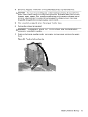
...the power-on state, voltage is present may cause irreparable damage to cool before adding or removing memory modules. Rotate up the internal drive bay housing to access the memory module sockets on a stand, remove the computer from the stand. 6. Regardless of personal injury... any external devices. Remove the computer access panel. Adding or removing memory modules while voltage is always supplied to drain before touching. 7. Figure 3-8 Rotating the Drive Cage Up Installing Additional Memory 53 Disconnect the power cord from hot surfaces, allow the internal system...
...the power-on state, voltage is present may cause irreparable damage to cool before adding or removing memory modules. Rotate up the internal drive bay housing to access the memory module sockets on a stand, remove the computer from the stand. 6. Regardless of personal injury... any external devices. Remove the computer access panel. Adding or removing memory modules while voltage is always supplied to drain before touching. 7. Figure 3-8 Rotating the Drive Cage Up Installing Additional Memory 53 Disconnect the power cord from hot surfaces, allow the internal system...
Hardware Reference Guide
Page 62
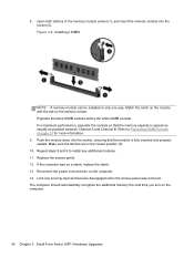
... any security devices that were disengaged when the access panel was on a stand, replace the stand. 13. Figure 3-9 Installing a DIMM NOTE: A memory module can be installed in the closed position (3). 10. Push the module down into the socket (2). Make sure the latches are in only one way...sockets so that the module is spread as equally as possible between Channel A and Channel B. The computer should automatically recognize the additional memory the next time you turn on page 51 for more information. 9. If the computer was removed. Reconnect the power cord and turn on ...
... any security devices that were disengaged when the access panel was on a stand, replace the stand. 13. Figure 3-9 Installing a DIMM NOTE: A memory module can be installed in the closed position (3). 10. Push the module down into the socket (2). Make sure the latches are in only one way...sockets so that the module is spread as equally as possible between Channel A and Channel B. The computer should automatically recognize the additional memory the next time you turn on page 51 for more information. 9. If the computer was removed. Reconnect the power cord and turn on ...
Hardware Reference Guide
Page 104
...48 SFF removal 47 SFF replacement 48 SFF security 80 front panel components MT 2 SFF 3 C computer operating guidelines 94 D DIMMs. See memory drives MT cable connections 25 MT installation 25 MT locations 24 SFF cable connections 60 SFF installation 60 SFF locations 59 E electrostatic discharge, preventing...padlock 75 Smart Cover Lock 90 M media card reader features 6 MT installation 29 MT removal 27 SFF installation 69 SFF removal 67 memory MT installation 17 MT socket population 18 MT specifications 17 SFF installation 51 SFF socket population 51 SFF specifications 51 O optical drive cleaning...
...48 SFF removal 47 SFF replacement 48 SFF security 80 front panel components MT 2 SFF 3 C computer operating guidelines 94 D DIMMs. See memory drives MT cable connections 25 MT installation 25 MT locations 24 SFF cable connections 60 SFF installation 60 SFF locations 59 E electrostatic discharge, preventing...padlock 75 Smart Cover Lock 90 M media card reader features 6 MT installation 29 MT removal 27 SFF installation 69 SFF removal 67 memory MT installation 17 MT socket population 18 MT specifications 17 SFF installation 51 SFF socket population 51 SFF specifications 51 O optical drive cleaning...
Hardware Reference Guide
Page 105
... Business PC Security Lock 76 SFF padlock 75 Smart Cover Lock 90 serial number locations 10 shipping preparation 95 Smart Cover Lock 90 specifications MT memory 17 SFF memory 51 Index 97
... Business PC Security Lock 76 SFF padlock 75 Smart Cover Lock 90 serial number locations 10 shipping preparation 95 Smart Cover Lock 90 specifications MT memory 17 SFF memory 51 Index 97

Maintenance and Service Guide Pro 6305 Microtower Business PC Pro 6305 Small Form Factor Business PC
Page 7
Front Bezel Security ...57 Bezel Blanks ...59 Memory ...60 DIMMs ...60 DDR3-SDRAM DIMMs 60 Populating DIMM Sockets 61 Installing DIMMs ...62 Expansion Cards ...64 WLAN module ...67 System Board Connections ...69 Drives ...... Replacement Procedures Small Form Factor (SFF) Chassis 99 Preparation for Disassembly ...99 Access Panel ...100 Front Bezel ...101 Front Bezel Security ...102 Bezel Blanks ...104 Memory ...105 DIMMs ...105 DDR3-SDRAM DIMMs 105 Populating DIMM Sockets 106 Installing DIMMs 107 Expansion Card ...109 WLAN module ...113 System Board Connections ...115 vii
Front Bezel Security ...57 Bezel Blanks ...59 Memory ...60 DIMMs ...60 DDR3-SDRAM DIMMs 60 Populating DIMM Sockets 61 Installing DIMMs ...62 Expansion Cards ...64 WLAN module ...67 System Board Connections ...69 Drives ...... Replacement Procedures Small Form Factor (SFF) Chassis 99 Preparation for Disassembly ...99 Access Panel ...100 Front Bezel ...101 Front Bezel Security ...102 Bezel Blanks ...104 Memory ...105 DIMMs ...105 DDR3-SDRAM DIMMs 105 Populating DIMM Sockets 106 Installing DIMMs 107 Expansion Card ...109 WLAN module ...113 System Board Connections ...115 vii
Maintenance and Service Guide Pro 6305 Microtower Business PC Pro 6305 Small Form Factor Business PC
Page 8
... ...158 Solving Audio Problems ...163 Solving Printer Problems ...165 Solving Keyboard and Mouse Problems 166 Solving Hardware Installation Problems 169 Solving Network Problems ...171 Solving Memory Problems ...175 Solving Processor Problems 176 Solving CD-ROM and DVD Problems 177 Solving USB Flash Drive Problems 179 Solving Front Panel Component Problems 180...
... ...158 Solving Audio Problems ...163 Solving Printer Problems ...165 Solving Keyboard and Mouse Problems 166 Solving Hardware Installation Problems 169 Solving Network Problems ...171 Solving Memory Problems ...175 Solving Processor Problems 176 Solving CD-ROM and DVD Problems 177 Solving USB Flash Drive Problems 179 Solving Front Panel Component Problems 180...


