
Aurora R5 Service Manual
Page 5
Removing the power-supply unit 46 Prerequisites...46 Procedure...46 Replacing the power-supply unit 53 Procedure...53 Post-requisites 53 Removing the processor-cooling assembly...........54 Prerequisites...54 Procedure...55 Replacing the processor-cooling assembly............57 Procedure...57 Post-requisites 57 Removing the coin-cell battery 58 Prerequisites...58 Procedure...58 Replacing the coin-cell battery 60 Procedure...60 Post-requisites 60 Removing the memory modules 61 Prerequisites...61 Procedure...61 Replacing the memory modules 63 Procedure...63 Post-requisites 65 5
Removing the power-supply unit 46 Prerequisites...46 Procedure...46 Replacing the power-supply unit 53 Procedure...53 Post-requisites 53 Removing the processor-cooling assembly...........54 Prerequisites...54 Procedure...55 Replacing the processor-cooling assembly............57 Procedure...57 Post-requisites 57 Removing the coin-cell battery 58 Prerequisites...58 Procedure...58 Replacing the coin-cell battery 60 Procedure...60 Post-requisites 60 Removing the memory modules 61 Prerequisites...61 Procedure...61 Replacing the memory modules 63 Procedure...63 Post-requisites 65 5
Aurora R5 Service Manual
Page 14
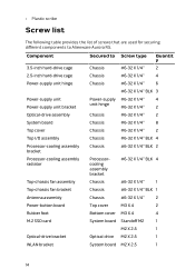
...Alienware Aurora R5. • Plastic scribe Screw list The following table provides the list of screws that are used for securing different components to Screw type Chassis #6-32 X 1/4'' Quantit y 2 2.5-inch hard-drive cage Chassis #6-32 X 1/4'' 4 Power-supply unit hinge Chassis #6-32 X 1/4'' 6 #6-32 X 1/4'' BLK 3 Power-supply unit Power-supply unit bracket Power-supply... 1/4'' 1 Top-chassis fan bracket Chassis #6-32 X 1/4'' BLK 1 Antenna assembly Chassis #6-32 X 1/4'' 2 Power-button board Top cover M3 X 4 2 Rubber foot Bottom cover M3 X 4 4 M.2 SSD card System ...
...Alienware Aurora R5. • Plastic scribe Screw list The following table provides the list of screws that are used for securing different components to Screw type Chassis #6-32 X 1/4'' Quantit y 2 2.5-inch hard-drive cage Chassis #6-32 X 1/4'' 4 Power-supply unit hinge Chassis #6-32 X 1/4'' 6 #6-32 X 1/4'' BLK 3 Power-supply unit Power-supply unit bracket Power-supply... 1/4'' 1 Top-chassis fan bracket Chassis #6-32 X 1/4'' BLK 1 Antenna assembly Chassis #6-32 X 1/4'' 2 Power-button board Top cover M3 X 4 2 Rubber foot Bottom cover M3 X 4 4 M.2 SSD card System ...

Aurora R5 Service Manual
Page 16
Technical overview WARNING: Before working inside your computer, read the safety information that shipped with your computer and follow the instructions in Before working inside your computer 1 power-supply unit 16 2 optical-drive assembly After working inside your computer, follow the steps in After working inside your computer. Inside view of your computer. For more safety best practices, see the Regulatory Compliance home page at www.dell.com/regulatory_compliance.
Technical overview WARNING: Before working inside your computer, read the safety information that shipped with your computer and follow the instructions in Before working inside your computer 1 power-supply unit 16 2 optical-drive assembly After working inside your computer, follow the steps in After working inside your computer. Inside view of your computer. For more safety best practices, see the Regulatory Compliance home page at www.dell.com/regulatory_compliance.

Aurora R5 Service Manual
Page 46
Removing the power-supply unit WARNING: Before working inside your computer, read the safety information that you can reroute them correctly after you remove them so that shipped with ... Remove the left-side cover. For more safety best practices, see the Regulatory Compliance home page at www.dell.com/regulatory_compliance. Procedure NOTE: Note the routing of all cables as you replace the power supply. 1 Lay the computer on the right side. 46 After working inside your computer, follow the steps in After...
Removing the power-supply unit WARNING: Before working inside your computer, read the safety information that you can reroute them correctly after you remove them so that shipped with ... Remove the left-side cover. For more safety best practices, see the Regulatory Compliance home page at www.dell.com/regulatory_compliance. Procedure NOTE: Note the routing of all cables as you replace the power supply. 1 Lay the computer on the right side. 46 After working inside your computer, follow the steps in After...

Aurora R5 Service Manual
Page 47
2 Slide the power supply unit release latches towards the top of the computer. 1 power-supply unit 3 power supply unit release latches (2) 2 chassis 47
2 Slide the power supply unit release latches towards the top of the computer. 1 power-supply unit 3 power supply unit release latches (2) 2 chassis 47

Aurora R5 Service Manual
Page 48
3 Lift the power-supply unit while pressing and holding the graphics-card bracket. 1 power-supply unit 3 chassis 2 graphics-card bracket 48
3 Lift the power-supply unit while pressing and holding the graphics-card bracket. 1 power-supply unit 3 chassis 2 graphics-card bracket 48

Aurora R5 Service Manual
Page 49
4 Rotate the power-supply unit away from the chassis. 1 power-supply unit 5 Press the releasing clip on the power-cable connectors and disconnect the power cables from the graphics card. 6 Disconnect the power cables from the optical drive and hard drives. 49
4 Rotate the power-supply unit away from the chassis. 1 power-supply unit 5 Press the releasing clip on the power-cable connectors and disconnect the power cables from the graphics card. 6 Disconnect the power cables from the optical drive and hard drives. 49

Aurora R5 Service Manual
Page 50
7 Disconnect the processor-power cable and system-board power cable from the system board. 1 power-supply unit 3 graphics-card power cables (2) 5 hard-drive power cable 7 optical-drive power cable 2 hard-drive power cable 4 releasing clips (2) 6 processor-power cable 8 system-board power cable 8 Rotate the power-supply unit towards the chassis until the unit snaps into place. 9 Remove the screws that secure the power-supply unit bracket to the power-supply unit. 50
7 Disconnect the processor-power cable and system-board power cable from the system board. 1 power-supply unit 3 graphics-card power cables (2) 5 hard-drive power cable 7 optical-drive power cable 2 hard-drive power cable 4 releasing clips (2) 6 processor-power cable 8 system-board power cable 8 Rotate the power-supply unit towards the chassis until the unit snaps into place. 9 Remove the screws that secure the power-supply unit bracket to the power-supply unit. 50

Aurora R5 Service Manual
Page 51
10 Lift the power-supply unit bracket off the power-supply unit. 1 chassis 3 power-supply unit bracket 2 screws (2) 4 power-supply unit 11 Remove the screws that secure the power-supply unit to the chassis. 51
10 Lift the power-supply unit bracket off the power-supply unit. 1 chassis 3 power-supply unit bracket 2 screws (2) 4 power-supply unit 11 Remove the screws that secure the power-supply unit to the chassis. 51

Aurora R5 Service Manual
Page 52
12 Lift the power-supply unit, along with the cables, off the chassis. 1 chassis 3 screws (4) 2 power-supply unit 52
12 Lift the power-supply unit, along with the cables, off the chassis. 1 chassis 3 screws (4) 2 power-supply unit 52
Aurora R5 Service Manual
Page 53
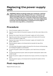
... bottom of the computer. Procedure 1 Place the power supply on the chassis. 2 Align the screw holes on the power-supply unit with your computer and follow the instructions in Before working inside your computer. For more safety best practices, see the Regulatory Compliance home page at www.dell.com/regulatory_compliance. After working inside your computer...
... bottom of the computer. Procedure 1 Place the power supply on the chassis. 2 Align the screw holes on the power-supply unit with your computer and follow the instructions in Before working inside your computer. For more safety best practices, see the Regulatory Compliance home page at www.dell.com/regulatory_compliance. After working inside your computer...

Aurora R5 Service Manual
Page 55
Procedure 1 Remove the screws that secure the radiator and fan assembly to the radiator and fan cage. 1 screws (4) 2 radiator and fan cage 2 Follow the procedure from step 1 to step 4 in "Removing the power-supply unit". 3 Disconnect the processor-cooling assembly cables from the system board. 4 In sequential order (as indicated on the processor cooler), loosen the captive screws that secure the processor cooler to the system board. 55
Procedure 1 Remove the screws that secure the radiator and fan assembly to the radiator and fan cage. 1 screws (4) 2 radiator and fan cage 2 Follow the procedure from step 1 to step 4 in "Removing the power-supply unit". 3 Disconnect the processor-cooling assembly cables from the system board. 4 In sequential order (as indicated on the processor cooler), loosen the captive screws that secure the processor cooler to the system board. 55

Aurora R5 Service Manual
Page 57
... safety best practices, see the Regulatory Compliance home page at www.dell.com/regulatory_compliance. Replacing the processorcooling assembly WARNING: Before working inside your computer, read the safety information that secure the radiator and fan assembly to step 11 in "Replacing the power-supply unit". 8 Replace the screws that shipped with your computer and...
... safety best practices, see the Regulatory Compliance home page at www.dell.com/regulatory_compliance. Replacing the processorcooling assembly WARNING: Before working inside your computer, read the safety information that secure the radiator and fan assembly to step 11 in "Replacing the power-supply unit". 8 Replace the screws that shipped with your computer and...
Aurora R5 Service Manual
Page 58
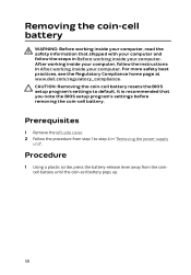
... inside your computer. For more safety best practices, see the Regulatory Compliance home page at www.dell.com/regulatory_compliance. CAUTION: Removing the coin-cell battery resets the BIOS setup program's settings to step 4 in "Removing the power-supply unit". Removing the coin-cell battery WARNING: Before working inside your computer, read the safety...
... inside your computer. For more safety best practices, see the Regulatory Compliance home page at www.dell.com/regulatory_compliance. CAUTION: Removing the coin-cell battery resets the BIOS setup program's settings to step 4 in "Removing the power-supply unit". Removing the coin-cell battery WARNING: Before working inside your computer, read the safety...

Aurora R5 Service Manual
Page 60
... battery into the battery socket with your computer and follow the instructions in "Replacing the power-supply unit". 2 Replace the left-side cover. 60 For more safety best practices, see the Regulatory Compliance home page at www.dell.com/regulatory_compliance. Procedure Insert a new coin-cell battery (CR2032) into place. Post-requisites 1 Follow the...
... battery into the battery socket with your computer and follow the instructions in "Replacing the power-supply unit". 2 Replace the left-side cover. 60 For more safety best practices, see the Regulatory Compliance home page at www.dell.com/regulatory_compliance. Procedure Insert a new coin-cell battery (CR2032) into place. Post-requisites 1 Follow the...

Aurora R5 Service Manual
Page 61
... at www.dell.com/regulatory_compliance. After working inside your computer, follow the steps in Before working inside your computer. Procedure 1 Locate the memory-module slots on the system board. For more safety best practices, see "System-board components". 2 Push the securing clips away from step 1 to step 4 in "Removing the power-supply unit...
... at www.dell.com/regulatory_compliance. After working inside your computer, follow the steps in Before working inside your computer. Procedure 1 Locate the memory-module slots on the system board. For more safety best practices, see "System-board components". 2 Push the securing clips away from step 1 to step 4 in "Removing the power-supply unit...

Aurora R5 Service Manual
Page 65
Post-requisites 1 Follow the procedure from step 10 to step 11 in "Replacing the power-supply unit". 2 Replace the left-side cover. 65
Post-requisites 1 Follow the procedure from step 10 to step 11 in "Replacing the power-supply unit". 2 Replace the left-side cover. 65

Aurora R5 Service Manual
Page 66
After working inside your computer, follow the steps in "Removing the power-supply unit". CAUTION: To avoid data loss, do not remove the solid-state drive while the computer is in After working inside your computer. Exercise care ... handling the solid-state drive. Procedure 1 Locate the solid-state drive slot on state. For more information, see the Regulatory Compliance home page at www.dell.com/regulatory_compliance. For more safety best practices, see "System-board components". 2 Remove the screw that shipped with your computer and follow the instructions in sleep...
After working inside your computer, follow the steps in "Removing the power-supply unit". CAUTION: To avoid data loss, do not remove the solid-state drive while the computer is in After working inside your computer. Exercise care ... handling the solid-state drive. Procedure 1 Locate the solid-state drive slot on state. For more information, see the Regulatory Compliance home page at www.dell.com/regulatory_compliance. For more safety best practices, see "System-board components". 2 Remove the screw that shipped with your computer and follow the instructions in sleep...

Aurora R5 Service Manual
Page 69
3 Press the other end of the solid-state drive down and replace the screw that secure the solid-state drive to the system board. 1 solid-state drive 3 tab 5 solid-state drive slot 2 notch 4 screw 6 system board Post-requisites 1 Follow the procedure from step 10 to step 11 in "Replacing the power-supply unit". 2 Replace the left-side cover. 69
3 Press the other end of the solid-state drive down and replace the screw that secure the solid-state drive to the system board. 1 solid-state drive 3 tab 5 solid-state drive slot 2 notch 4 screw 6 system board Post-requisites 1 Follow the procedure from step 10 to step 11 in "Replacing the power-supply unit". 2 Replace the left-side cover. 69
Aurora R5 Service Manual
Page 70
Prerequisites 1 Remove the left-side cover. 2 Follow the procedure from step 1 to step 4 in "Removing the power-supply unit". 70 After working inside your computer, follow the steps in Before working inside your computer. For more safety best practices, see the Regulatory Compliance home page at www.dell.com/regulatory_compliance. Removing the graphics card WARNING: Before working inside your computer, read the safety information that shipped with your computer and follow the instructions in After working inside your computer.
Prerequisites 1 Remove the left-side cover. 2 Follow the procedure from step 1 to step 4 in "Removing the power-supply unit". 70 After working inside your computer, follow the steps in Before working inside your computer. For more safety best practices, see the Regulatory Compliance home page at www.dell.com/regulatory_compliance. Removing the graphics card WARNING: Before working inside your computer, read the safety information that shipped with your computer and follow the instructions in After working inside your computer.


