View
Page 2
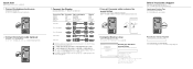
... the keyboard and mouse 2 Connect the network cable (optional) 3 Connect the Display Connection Type Computer Cable and Adapter VGA VGA Display DVI DVI (optional) DVI VGA (optional) HDMI HDMI HDMI DVI NOTE: If you ordered your computer with an optional discrete graphics card, connect the display to the port on your discrete graphics card 4 Connect the power cable and press the power button 5 Complete Windows setup 完成 Windows Windows 設定 Windows Windows Record your Windows password...
... the keyboard and mouse 2 Connect the network cable (optional) 3 Connect the Display Connection Type Computer Cable and Adapter VGA VGA Display DVI DVI (optional) DVI VGA (optional) HDMI HDMI HDMI DVI NOTE: If you ordered your computer with an optional discrete graphics card, connect the display to the port on your discrete graphics card 4 Connect the power cable and press the power button 5 Complete Windows setup 完成 Windows Windows 設定 Windows Windows Record your Windows password...
Owners Manual
Page 1
Dell Inspiron 660 Owner's Manual Computer model: Inspiron 660 Regulatory model: D11M Regulatory type: D11M002
Dell Inspiron 660 Owner's Manual Computer model: Inspiron 660 Regulatory model: D11M Regulatory type: D11M002

Owners Manual
Page 3
Contents 1 Before You Begin 9 Turn Off Your Computer and Connected Devices . . . . . 9 Safety Instructions 9 Recommended Tools 10 2 After Working Inside Your Computer . . . 11 3 Technical Overview 13 Inside View of Your Computer 13 System Board Components 14 4 Computer Cover 17 Removing the Computer Cover 18 Replacing the Computer Cover 19 5 Memory Module(s 21 Removing the Memory Module(s 21 Replacing the Memory Module(s 22 Contents 3
Contents 1 Before You Begin 9 Turn Off Your Computer and Connected Devices . . . . . 9 Safety Instructions 9 Recommended Tools 10 2 After Working Inside Your Computer . . . 11 3 Technical Overview 13 Inside View of Your Computer 13 System Board Components 14 4 Computer Cover 17 Removing the Computer Cover 18 Replacing the Computer Cover 19 5 Memory Module(s 21 Removing the Memory Module(s 21 Replacing the Memory Module(s 22 Contents 3

Owners Manual
Page 4
6 Front Bezel 25 Removing the Front Bezel 25 Replacing the Front Bezel 27 7 Card Retention Bracket 29 Removing the Card Retention Bracket 29 Replacing the Card Retention Bracket 31 8 PCI Express Cards 33 Removing PCI Express Cards 33 Replacing PCI Express Cards 35 Configuring Your Computer After Removing or Installing the PCI Express Card 37 9 Mini-Card 39 Removing the Mini-Card 40 Replacing the Mini-Card 41 10 Hard Drive(s 43 Removing the Hard Drive(s 43 Replacing the Hard Drive(s 48 4 Contents
6 Front Bezel 25 Removing the Front Bezel 25 Replacing the Front Bezel 27 7 Card Retention Bracket 29 Removing the Card Retention Bracket 29 Replacing the Card Retention Bracket 31 8 PCI Express Cards 33 Removing PCI Express Cards 33 Replacing PCI Express Cards 35 Configuring Your Computer After Removing or Installing the PCI Express Card 37 9 Mini-Card 39 Removing the Mini-Card 40 Replacing the Mini-Card 41 10 Hard Drive(s 43 Removing the Hard Drive(s 43 Replacing the Hard Drive(s 48 4 Contents
Owners Manual
Page 6
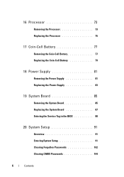
16 Processor 73 Removing the Processor 73 Replacing the Processor 75 17 Coin-Cell Battery 77 Removing the Coin-Cell Battery 77 Replacing the Coin-Cell Battery 79 18 Power Supply 81 Removing the Power Supply 81 Replacing the Power Supply 83 19 System Board 85 Removing the System Board 85 Replacing the System Board 87 Entering the Service Tag in the BIOS 88 20 System Setup 91 Overview 91 Entering System Setup 91 Clearing Forgotten Passwords 102 Clearing CMOS Passwords 104 6 Contents
16 Processor 73 Removing the Processor 73 Replacing the Processor 75 17 Coin-Cell Battery 77 Removing the Coin-Cell Battery 77 Replacing the Coin-Cell Battery 79 18 Power Supply 81 Removing the Power Supply 81 Replacing the Power Supply 83 19 System Board 85 Removing the System Board 85 Replacing the System Board 87 Entering the Service Tag in the BIOS 88 20 System Setup 91 Overview 91 Entering System Setup 91 Clearing Forgotten Passwords 102 Clearing CMOS Passwords 104 6 Contents

Owners Manual
Page 9
... open programs before opening the computer cover or panels. NOTE: If you turn off . WARNING: Disconnect all power sources before you are using a different operating system, see the Regulatory Compliance Homepage at dell.com/regulatory_compliance. CAUTION: To avoid damaging the components and cards, handle them by their electrical outlets. 4 Disconnect all telephone cables, network cables, and attached devices from their edges and avoid touching pins...
... open programs before opening the computer cover or panels. NOTE: If you turn off . WARNING: Disconnect all power sources before you are using a different operating system, see the Regulatory Compliance Homepage at dell.com/regulatory_compliance. CAUTION: To avoid damaging the components and cards, handle them by their electrical outlets. 4 Disconnect all telephone cables, network cables, and attached devices from their edges and avoid touching pins...
Owners Manual
Page 10
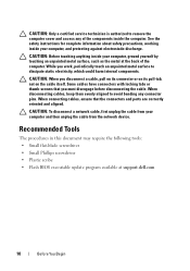
... metal at support.dell.com 10 Before You Begin CAUTION: When you work, periodically touch an unpainted metal surface to avoid bending any of the computer. CAUTION: Only a certified service technician is authorized to remove the computer cover and access any connector pins. CAUTION: Before touching anything inside your computer and then unplug the cable from the network device. Some cables have connectors with locking...
... metal at support.dell.com 10 Before You Begin CAUTION: When you work, periodically touch an unpainted metal surface to avoid bending any of the computer. CAUTION: Only a certified service technician is authorized to remove the computer cover and access any connector pins. CAUTION: Before touching anything inside your computer and then unplug the cable from the network device. Some cables have connectors with locking...

Owners Manual
Page 11
After Working Inside Your Computer 11 Failure to their electrical outlets CAUTION: Before turning on your computer, replace all screws and ensure that no stray screws remain inside your computer • Connect any external devices, cables, cards, and any other part you removed before working on your computer • Connect your computer and all attached devices to do so may damage your computer. • Turn on your computer...
After Working Inside Your Computer 11 Failure to their electrical outlets CAUTION: Before turning on your computer, replace all screws and ensure that no stray screws remain inside your computer • Connect any external devices, cables, cards, and any other part you removed before working on your computer • Connect your computer and all attached devices to do so may damage your computer. • Turn on your computer...

Owners Manual
Page 23
... the memory module correctly, the securing clips snap into position and the securing clip locks in place. If a message appears stating that the memory is installed correctly, click Start→ Control Panel→ System. Check the amount of the memory module. 2 1 1 cutouts (2) 2 securing clips (2) (snapped in "After Working Inside Your Computer" on page 11. 3 Connect your computer. See "Replacing the Computer Cover...
... the memory module correctly, the securing clips snap into position and the securing clip locks in place. If a message appears stating that the memory is installed correctly, click Start→ Control Panel→ System. Check the amount of the memory module. 2 1 1 cutouts (2) 2 securing clips (2) (snapped in "After Working Inside Your Computer" on page 11. 3 Connect your computer. See "Replacing the Computer Cover...

Owners Manual
Page 37
... sound card's connectors. 1 Enter system setup. See "System Setup" on page 91. 2 Go to Onboard Audio Controller and then change the setting to Enabled. 3 Connect the network cable to the computer's back panel connectors. 1 Enter system setup. See "System Setup" on installing drivers and software for your card, see the Quick Start Guide. Sound card Network card Installed 1 Enter system setup. Removed 1 Enter system setup. PCI Express Cards 37 For information on page 91. 2 Go to Onboard LAN Controller and then change the setting to Disabled. 3 Connect the external audio devices...
... sound card's connectors. 1 Enter system setup. See "System Setup" on page 91. 2 Go to Onboard Audio Controller and then change the setting to Enabled. 3 Connect the network cable to the computer's back panel connectors. 1 Enter system setup. See "System Setup" on installing drivers and software for your card, see the Quick Start Guide. Sound card Network card Installed 1 Enter system setup. Removed 1 Enter system setup. PCI Express Cards 37 For information on page 91. 2 Go to Onboard LAN Controller and then change the setting to Disabled. 3 Connect the external audio devices...

Owners Manual
Page 47
See "System Setup" on each side) that secure the hard-drive brackets to the hard-drive. 6 Remove the hard-drive brackets off the hard drive. 1 3 2 1 hard drive 3 hard-drive bracket 2 screws (2) 7 If removing the hard drive changes the drive configuration, ensure that you reflect these changes in system setup. Hard Drive(s) 47 5 Remove the screws (one on page 91.
See "System Setup" on each side) that secure the hard-drive brackets to the hard-drive. 6 Remove the hard-drive brackets off the hard drive. 1 3 2 1 hard drive 3 hard-drive bracket 2 screws (2) 7 If removing the hard drive changes the drive configuration, ensure that you reflect these changes in system setup. Hard Drive(s) 47 5 Remove the screws (one on page 91.

Owners Manual
Page 87
... you removed with the replacement system board to the chassis. 3 Route and connect the cables that they are identical. Postrequisites 1 Replace the processor. See "Replacing the Memory Module(s)" on the replacement system board is preset at the factory. NOTE: Jumper settings on page 22. 4 Replace any PCI-Express cards, if applicable. System Board 87 NOTE: For information on system board connectors, see "System Board Components" on page 41. 6 Replace the computer cover. See "Replacing...
... you removed with the replacement system board to the chassis. 3 Route and connect the cables that they are identical. Postrequisites 1 Replace the processor. See "Replacing the Memory Module(s)" on the replacement system board is preset at the factory. NOTE: Jumper settings on page 22. 4 Replace any PCI-Express cards, if applicable. System Board 87 NOTE: For information on system board connectors, see "System Board Components" on page 41. 6 Replace the computer cover. See "Replacing...

Owners Manual
Page 91
.... Entering System Setup 1 Turn on page 9. If you note the system-setup screen information for this keystroke is displayed, watch for the F2 prompt to : • Get information about the hardware installed on your computer, such as the amount of RAM, the size of the hard drive, and so on • Change the system configuration information • Set or change a user-selectable option, such as the user password, type of hard drive installed, enabling...
.... Entering System Setup 1 Turn on page 9. If you note the system-setup screen information for this keystroke is displayed, watch for the F2 prompt to : • Get information about the hardware installed on your computer, such as the amount of RAM, the size of the hard drive, and so on • Change the system configuration information • Set or change a user-selectable option, such as the user password, type of hard drive installed, enabling...

Owners Manual
Page 93
... Displays the processor L3 cache size Main - System Setup Options NOTE: Depending on your computer and installed devices, the items listed in mm/dd/yyyy format Service Tag Displays the Service Tag of the computer when the Service Tag is present Displays a field to input the Service Tag manually when the Service Tag is absent Asset Tag Displays the asset tag of installed memory System Setup 93 Main - Memory Information Memory Installed Memory Running Speed Memory...
... Displays the processor L3 cache size Main - System Setup Options NOTE: Depending on your computer and installed devices, the items listed in mm/dd/yyyy format Service Tag Displays the Service Tag of the computer when the Service Tag is present Displays a field to input the Service Tag manually when the Service Tag is absent Asset Tag Displays the asset tag of installed memory System Setup 93 Main - Memory Information Memory Installed Memory Running Speed Memory...
Owners Manual
Page 96
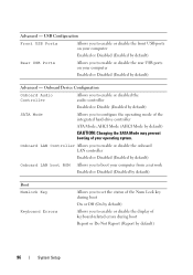
... enable or disable the rear USB ports on your computer Enabled or Disabled (Enabled by default) SATA Mode Allows you to configure the operating mode of your computer from a network Enabled or Disabled (Disabled by default) Boot Numlock Key Keyboard Errors Allows you to set the status of the Num Lock key during boot On or Off (On by default) Allows you to enable or disable the display of keyboard-related errors during boot Report or Do Not Report (Report by default) CAUTION: Changing the SATA Mode...
... enable or disable the rear USB ports on your computer Enabled or Disabled (Enabled by default) SATA Mode Allows you to configure the operating mode of your computer from a network Enabled or Disabled (Disabled by default) Boot Numlock Key Keyboard Errors Allows you to set the status of the Num Lock key during boot On or Off (On by default) Allows you to enable or disable the display of keyboard-related errors during boot Report or Do Not Report (Report by default) CAUTION: Changing the SATA Mode...

Owners Manual
Page 97
... option can be powered on by LAN/WLAN special LAN or wireless LAN signals Enabled or Disabled (Disabled by default) AC Recovery Allows you to configure the behavior of your computer after it recovers from a power failure Power Off, Power On, or Last Power State (Power Off by default) Auto Power On Allows you to set to enable or disable booting from the available devices Displays the first boot device Displays the second boot device Displays the third boot device Displays the fourth boot device Displays the fifth boot device Power Wake...
... option can be powered on by LAN/WLAN special LAN or wireless LAN signals Enabled or Disabled (Disabled by default) AC Recovery Allows you to configure the behavior of your computer after it recovers from a power failure Power Off, Power On, or Last Power State (Power Off by default) Auto Power On Allows you to set to enable or disable booting from the available devices Displays the first boot device Displays the second boot device Displays the third boot device Displays the fourth boot device Displays the fifth boot device Power Wake...

Owners Manual
Page 100
...; Network - The computer attempts to change the boot sequence for devices. Insert the memory device into a USB port and restart the computer. If no operating system is on the floppy disk, the computer generates an error message. • Hard Drive - The BIOS detects the device and adds the USB flash option to boot from the CD/DVD/CD-RW drive. To ensure that the Onboard LAN Boot ROM option is found on page 91. 100 System Setup...
...; Network - The computer attempts to change the boot sequence for devices. Insert the memory device into a USB port and restart the computer. If no operating system is on the floppy disk, the computer generates an error message. • Hard Drive - The BIOS detects the device and adds the USB flash option to boot from the CD/DVD/CD-RW drive. To ensure that the Onboard LAN Boot ROM option is found on page 91. 100 System Setup...
Owners Manual
Page 101
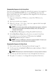
... screen, press . For example, if you see the Microsoft Windows desktop. NOTE: If you wait too long and the operating system logo appears, continue to wait until you are booting from a USB device, connect the USB device to a USB port. 2 Turn on page 91. 2 Use the arrow keys to highlight the Boot menu option and press to access the menu. Changing Boot Sequence for example, to boot from the CD/DVD/CD-RW drive to run Dell Diagnostics...
... screen, press . For example, if you see the Microsoft Windows desktop. NOTE: If you wait too long and the operating system logo appears, continue to wait until you are booting from a USB device, connect the USB device to a USB port. 2 Turn on page 91. 2 Use the arrow keys to highlight the Boot menu option and press to access the menu. Changing Boot Sequence for example, to boot from the CD/DVD/CD-RW drive to run Dell Diagnostics...
Owners Manual
Page 102
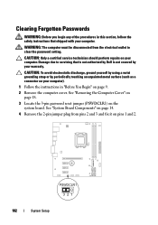
... Board Components" on page 14. 4 Remove the 2-pin jumper plug from the electrical outlet to servicing that shipped with your warranty. CAUTION: To avoid electrostatic discharge, ground yourself by using a wrist grounding strap or by your computer. See "Removing the Computer Cover" on page 18. 3 Locate the 3-pin password reset jumper (PSWDCLR1) on pins 1 and 2. PSWDCLR1 102 System Setup CAUTION: Only a certified service technician should perform repairs on...
... Board Components" on page 14. 4 Remove the 2-pin jumper plug from the electrical outlet to servicing that shipped with your warranty. CAUTION: To avoid electrostatic discharge, ground yourself by using a wrist grounding strap or by your computer. See "Removing the Computer Cover" on page 18. 3 Locate the 3-pin password reset jumper (PSWDCLR1) on pins 1 and 2. PSWDCLR1 102 System Setup CAUTION: Only a certified service technician should perform repairs on...
Owners Manual
Page 104
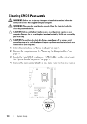
... discharge, ground yourself by using a wrist grounding strap or by your computer. See "System Board Components" on page 14. 4 Remove the 2-pin jumper plug from the electrical outlet to servicing that shipped with your computer. CAUTION: Only a certified service technician should perform repairs on pins 1 and 2. 104 System Setup CMOSCLR1 See "Removing the Computer Cover" on page 18. 3 Locate the 3-pin CMOS reset jumper (CMOSCLR1) on the system...
... discharge, ground yourself by using a wrist grounding strap or by your computer. See "System Board Components" on page 14. 4 Remove the 2-pin jumper plug from the electrical outlet to servicing that shipped with your computer. CAUTION: Only a certified service technician should perform repairs on pins 1 and 2. 104 System Setup CMOSCLR1 See "Removing the Computer Cover" on page 18. 3 Locate the 3-pin CMOS reset jumper (CMOSCLR1) on the system...


