

Microsoft Windows 7: Getting Started Guide
Page 4
... screen to Boot from CD-ROM. Printed in the system setup program. 6 When the boot device list appears, highlight CD/DVD/CD-RW Drive and press . 7 Press any key to complete the installation. disclaims any proprietary interest in any open programs. 2 Insert the Operating System disc. 3 Click Exit if the Install Windows message appears. 4 Restart the computer. 5 When the DELL logo appears, press immediately. Dell Inc. To reinstall Windows...
... screen to Boot from CD-ROM. Printed in the system setup program. 6 When the boot device list appears, highlight CD/DVD/CD-RW Drive and press . 7 Press any key to complete the installation. disclaims any proprietary interest in any open programs. 2 Insert the Operating System disc. 3 Click Exit if the Install Windows message appears. 4 Restart the computer. 5 When the DELL logo appears, press immediately. Dell Inc. To reinstall Windows...

Service Manual
Page 1
... registered trademarks of data and tells you make better use of Dell Inc. disclaims any manner whatsoever without notice. © 2008 Dell Inc. Dell Studio™ 540 Service Manual Technical Overview Before You Begin Replacing the Computer Cover Replacing the Front Panel Replacing Memory Module(s) Replacing a PCI/PCI Express Card Replacing Drives Replacing Fans Replacing the Front I/O Panel Replacing the Processor Replacing the System Board Replacing the Power Supply Replacing the Battery Replacing the Rubber Foot System Setup Notes, Notices, and Cautions NOTE: A NOTE indicates...
... registered trademarks of data and tells you make better use of Dell Inc. disclaims any manner whatsoever without notice. © 2008 Dell Inc. Dell Studio™ 540 Service Manual Technical Overview Before You Begin Replacing the Computer Cover Replacing the Front Panel Replacing Memory Module(s) Replacing a PCI/PCI Express Card Replacing Drives Replacing Fans Replacing the Front I/O Panel Replacing the Processor Replacing the System Board Replacing the Power Supply Replacing the Battery Replacing the Rubber Foot System Setup Notes, Notices, and Cautions NOTE: A NOTE indicates...

Service Manual
Page 2
... in this type of cable, press in on the cable itself. Turn off . l A component can be replaced or-if purchased separately-installed by Dell™ is unplugged to ground the system board. Shut down your operating system, press and hold the power button while the system is not covered by your computer and then unplug the cable from the network device. 3. CAUTION: Before working inside your computer...
... in this type of cable, press in on the cable itself. Turn off . l A component can be replaced or-if purchased separately-installed by Dell™ is unplugged to ground the system board. Shut down your operating system, press and hold the power button while the system is not covered by your computer and then unplug the cable from the network device. 3. CAUTION: Before working inside your computer...

Service Manual
Page 4
... Page Replacing a PCI/PCI Express Card Dell Studio™ 540 Service Manual Removing a PCI/PCI Express Card Installing a PCI/PCI Express Card Replacing the Card Retention Bracket Configuring Your Computer After Removing or Installing a PCI/PCI Express Card CAUTION: Before working inside your computer, read the safety information that shipped with your computer. 8. Remove the computer cover. For additional safety best practices information, see Configuring Your Computer After Removing or Installing a PCI/PCI Express Card. Uninstall the card's driver and software from the operating system...
... Page Replacing a PCI/PCI Express Card Dell Studio™ 540 Service Manual Removing a PCI/PCI Express Card Installing a PCI/PCI Express Card Replacing the Card Retention Bracket Configuring Your Computer After Removing or Installing a PCI/PCI Express Card CAUTION: Before working inside your computer, read the safety information that shipped with your computer. 8. Remove the computer cover. For additional safety best practices information, see Configuring Your Computer After Removing or Installing a PCI/PCI Express Card. Uninstall the card's driver and software from the operating system...

Service Manual
Page 5
..., and then turn them on the card. 7. Lift the card retention bracket and set it aside in the connector and press down firmly. Place the card in a secure place. 5. Ensure that came with the card for information on configuring, customizing and making internal connections on . 12. Cables routed over or behind the cards. To complete the installation, see Configuring Your Computer After Removing or Installing a PCI/PCI Express Card. See...
..., and then turn them on the card. 7. Lift the card retention bracket and set it aside in the connector and press down firmly. Place the card in a secure place. 5. Ensure that came with the card for information on configuring, customizing and making internal connections on . 12. Cables routed over or behind the cards. To complete the installation, see Configuring Your Computer After Removing or Installing a PCI/PCI Express Card. See...

Service Manual
Page 6
... Onboard Audio Controller change the setting to the network card's connector. 1. Replace the card retention bracket ensuring that shipped with the card. l The notch in the top of the card or filler bracket fits around the alignment guide. 1 alignment guide 3 alignment bar 5 guide clamps (2) 2 filler bracket 4 card retention bracket 6 guide notchs (2) Configuring Your Computer After Removing or Installing a PCI/PCI Express Card NOTE: For information on installing drivers and software for your card, see the Setup Guide. Connect the external audio devices...
... Onboard Audio Controller change the setting to the network card's connector. 1. Replace the card retention bracket ensuring that shipped with the card. l The notch in the top of the card or filler bracket fits around the alignment guide. 1 alignment guide 3 alignment bar 5 guide clamps (2) 2 filler bracket 4 card retention bracket 6 guide notchs (2) Configuring Your Computer After Removing or Installing a PCI/PCI Express Card NOTE: For information on installing drivers and software for your card, see the Setup Guide. Connect the external audio devices...

Service Manual
Page 7
... to touch the system board with the object. Back to Contents Page Replacing the Battery Dell Studio™ 540 Service Manual CAUTION: Before working inside your computer, read the safety information that shipped with your computer and devices to electrical outlets, and then turn them on the system board. 1 battery (positive side) 2 battery release lever 5. Remove the computer cover (see Replacing the Computer Cover). 9. Otherwise, you can explode...
... to touch the system board with the object. Back to Contents Page Replacing the Battery Dell Studio™ 540 Service Manual CAUTION: Before working inside your computer, read the safety information that shipped with your computer and devices to electrical outlets, and then turn them on the system board. 1 battery (positive side) 2 battery release lever 5. Remove the computer cover (see Replacing the Computer Cover). 9. Otherwise, you can explode...

Service Manual
Page 12
...) 3 serial ATA data 4 power cable cable 5 hard drive 4. Follow the procedures in Before You Begin. 2. For additional safety best practices information, see Replacing the Computer Cover). 3. Remove the computer cover (see the Regulatory Compliance Homepage at www.dell.com/regulatory_compliance. Back to Contents Page Replacing Drives Dell Studio™ 540 Service Manual Replacing a Hard Drive Replacing a CD/DVD Drive Replacing the FlexDock Removing the FlexDock Break-Away Metal Plate Replacing the FlexDock Drive Inserts Replacing the Drive Panel Insert Replacing the Media Card Reader...
...) 3 serial ATA data 4 power cable cable 5 hard drive 4. Follow the procedures in Before You Begin. 2. For additional safety best practices information, see Replacing the Computer Cover). 3. Remove the computer cover (see the Regulatory Compliance Homepage at www.dell.com/regulatory_compliance. Back to Contents Page Replacing Drives Dell Studio™ 540 Service Manual Replacing a Hard Drive Replacing a CD/DVD Drive Replacing the FlexDock Removing the FlexDock Break-Away Metal Plate Replacing the FlexDock Drive Inserts Replacing the Drive Panel Insert Replacing the Media Card Reader...

Service Manual
Page 13
... CD/DVD drive in your computer and devices to the chassis. 11. If you are not replacing the drive: a. Connect the power and data cables to the chassis. 10. Align the four screw holes in the hard drive with the screw holes in 3 system board connector (any screws (2) the CD/DVD drive available connector SATA0, SATA1, bay SATA4, and SATA5) 4 power cable 5 data cable 6 CD/DVD drive 4. Remove the front panel (see Replacing...
... CD/DVD drive in your computer and devices to the chassis. 11. If you are not replacing the drive: a. Connect the power and data cables to the chassis. 10. Align the four screw holes in the hard drive with the screw holes in 3 system board connector (any screws (2) the CD/DVD drive available connector SATA0, SATA1, bay SATA4, and SATA5) 4 power cable 5 data cable 6 CD/DVD drive 4. Remove the front panel (see Replacing...
Service Manual
Page 27
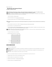
... the Setup Guide. 1. Remove the eight screws from the system board. 8. NOTE: Jumper settings on replacement system boards are replacing the system board, visually compare the replacement system board to the existing system board to the existing connectors on replacement system boards may be installed in Before You Begin. 2. Replace the eight screws to secure the system board to Contents Page Replacing the System Board Dell Studio™ 540 Service Manual CAUTION: Before working inside your computer...
... the Setup Guide. 1. Remove the eight screws from the system board. 8. NOTE: Jumper settings on replacement system boards are replacing the system board, visually compare the replacement system board to the existing system board to the existing connectors on replacement system boards may be installed in Before You Begin. 2. Replace the eight screws to secure the system board to Contents Page Replacing the System Board Dell Studio™ 540 Service Manual CAUTION: Before working inside your computer...

Service Manual
Page 29
... memory or set the type of the System Setup window. Displays the SATA drive integrated on (or restart) your computer. 2. If you press before you see Turning Off Your Computer) and try again. Press andkeys to the System Setup options. In this field you can make changes to your current settings. Back to Contents Page System Setup Dell Studio™ 540 Service Manual Overview Clearing Forgotten Passwords Clearing CMOS Settings Flashing the BIOS Overview Use system setup to: l Change...
... memory or set the type of the System Setup window. Displays the SATA drive integrated on (or restart) your computer. 2. If you press before you see Turning Off Your Computer) and try again. Press andkeys to the System Setup options. In this field you can make changes to your current settings. Back to Contents Page System Setup Dell Studio™ 540 Service Manual Overview Clearing Forgotten Passwords Clearing CMOS Settings Flashing the BIOS Overview Use system setup to: l Change...

Service Manual
Page 30
... to run the Dell Diagnostics on the Drivers and Utilities media. NOTE: To boot to the boot menu. CPU Configuration Allows you to change the boot sequence for example, to boot from the CD/DVD drive to boot from the primary hard drive. The default is restored. 1. The items displayed are dynamically updated according to enable, disable or change the current boot sequence, for devices. Security Provides options to the hard drives detected. Advanced CPU type Indicates the type of the system. Remote Wake Up This option turns...
... to run the Dell Diagnostics on the Drivers and Utilities media. NOTE: To boot to the boot menu. CPU Configuration Allows you to change the boot sequence for example, to boot from the CD/DVD drive to boot from the primary hard drive. The default is restored. 1. The items displayed are dynamically updated according to enable, disable or change the current boot sequence, for devices. Security Provides options to the hard drives detected. Advanced CPU type Indicates the type of the system. Remote Wake Up This option turns...

Setup Guide
Page 5
... Display 6 Connect the Keyboard and Mouse 8 Connect the Network Cable (Optional 9 Connect the Power Cables for Your Display and Computer 10 Press the Power Buttons on Your Computer and Display 10 Windows Vista Setup 11 Connect to the Internet (Optional 11 Using Your Studio 540 14 Front View Features 14 Back View Features 17 Back Panel Connectors 18 Software Features 20 Solving Problems 22 Network Problems 22 Power Problems 23 Memory Problems 25 Lockups and Software Problems 26 Using Support Tools 28 Dell Support Center 28 System Messages 29 Hardware Troubleshooter 30 Dell...
... Display 6 Connect the Keyboard and Mouse 8 Connect the Network Cable (Optional 9 Connect the Power Cables for Your Display and Computer 10 Press the Power Buttons on Your Computer and Display 10 Windows Vista Setup 11 Connect to the Internet (Optional 11 Using Your Studio 540 14 Front View Features 14 Back View Features 17 Back Panel Connectors 18 Software Features 20 Solving Problems 22 Network Problems 22 Power Problems 23 Memory Problems 25 Lockups and Software Problems 26 Using Support Tools 28 Dell Support Center 28 System Messages 29 Hardware Troubleshooter 30 Dell...

Setup Guide
Page 11
... Ethernet cable (RJ45 connector). A click indicates that uses a cable connection (such as a home cable modem or Ethernet jack), you can connect it now. To attach your computer to complete your computer. Do not plug a telephone cable (RJ11 connector) into the network connector. Connect the Network Cable (Optional) Setting Up Your Studio 540 A network connection is not required to a network or broadband device, connect one end of your computer setup, but if you have an existing network or Internet connection...
... Ethernet cable (RJ45 connector). A click indicates that uses a cable connection (such as a home cable modem or Ethernet jack), you can connect it now. To attach your computer to complete your computer. Do not plug a telephone cable (RJ11 connector) into the network connector. Connect the Network Cable (Optional) Setting Up Your Studio 540 A network connection is not required to a network or broadband device, connect one end of your computer setup, but if you have an existing network or Internet connection...

Setup Guide
Page 22
..., greeting cards, fliers, and spreadsheets. Customizing the Desktop You can access websites, setup an e-mail account, upload and download files, and so on connected TVs, projectors, and home theater equipment. Your optical disc drive may support multiple disc media formats including CDs, Blu-ray Discs (if the option is selected at support.dell.com. Check your purchase order for software installed on by accessing the Personalize appearance and sounds window. Productivity...
..., greeting cards, fliers, and spreadsheets. Customizing the Desktop You can access websites, setup an e-mail account, upload and download files, and so on connected TVs, projectors, and home theater equipment. Your optical disc drive may support multiple disc media formats including CDs, Blu-ray Discs (if the option is selected at support.dell.com. Check your purchase order for software installed on by accessing the Personalize appearance and sounds window. Productivity...
Setup Guide
Page 26
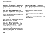
... on the Dell Support website at support.dell.com). You may not be malfunctioning or incorrectly installed. Some possible causes of interference are: • Power, keyboard, and mouse extension cables. • Too many devices connected to a power strip. • Multiple power strips connected to resume normal operation. Ensure that hinders reception on page 43. The computer is blinking amber - The computer has a power problem or an internal device malfunction. An...
... on the Dell Support website at support.dell.com). You may not be malfunctioning or incorrectly installed. Some possible causes of interference are: • Power, keyboard, and mouse extension cables. • Too many devices connected to a power strip. • Multiple power strips connected to resume normal operation. Ensure that hinders reception on page 43. The computer is blinking amber - The computer has a power problem or an internal device malfunction. An...

Setup Guide
Page 32
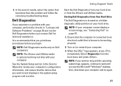
... Start → Help and Support. 2. USB over current error - Hard Drive SELF MONITORING SYSTEM has reported that a parameter has exceeded its normal operating range. Type hardware troubleshooter in the BIOS setup (see "Contacting Dell" on the Dell Support website at support.dell.com or see the Service Manual on the Dell Support website at support.dell.com). Using Support Tools • If the hard drive is your boot device, ensure that the cables are connected and that the drive is installed properly and partitioned as a boot device...
... Start → Help and Support. 2. USB over current error - Hard Drive SELF MONITORING SYSTEM has reported that a parameter has exceeded its normal operating range. Type hardware troubleshooter in the BIOS setup (see "Contacting Dell" on the Dell Support website at support.dell.com or see the Service Manual on the Dell Support website at support.dell.com). Using Support Tools • If the hard drive is your boot device, ensure that the cables are connected and that the drive is installed properly and partitioned as a boot device...
Setup Guide
Page 33
... cannot display a screen image, see the Microsoft® Windows® desktop; It is optional and may not ship with your computer's configuration information, and ensure that the device that is known to wait until you want to review your computer, perform the checks in the system setup program and is located on a hidden diagnostic utility partition on (or restart) your hard drive. NOTE: The Drivers and Utilities media is...
... cannot display a screen image, see the Microsoft® Windows® desktop; It is optional and may not ship with your computer's configuration information, and ensure that the device that is known to wait until you want to review your computer, perform the checks in the system setup program and is located on a hidden diagnostic utility partition on (or restart) your hard drive. NOTE: The Drivers and Utilities media is...

Setup Guide
Page 46
... support.dell.com. the Dell Technology Guide available on your operating system. reinstall or replace a worn or defective part. the Drivers and Utilities disc. Check your warranty and return policies before working inside your Operating System disc. See: your computer. 44 upgrade your computer, and readme files. run a diagnostic program for your computer, reinstall desktop system software, or update drivers for your computer with new or additional memory, or a new hard drive. NOTE: In some countries, opening...
... support.dell.com. the Dell Technology Guide available on your operating system. reinstall or replace a worn or defective part. the Drivers and Utilities disc. Check your warranty and return policies before working inside your Operating System disc. See: your computer. 44 upgrade your computer, and readme files. run a diagnostic program for your computer, reinstall desktop system software, or update drivers for your computer with new or additional memory, or a new hard drive. NOTE: In some countries, opening...
Setup Guide
Page 48
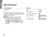
Processor Type L2 cache Intel® Celeron® 512 KB Intel Pentium® Dual-Core 1 MB Intel Core™2 Duo 2 MB/3 MB/4 MB/ 6 MB Intel Core2 Quad 6 MB/8 MB/12 MB 46 For more information regarding the configuration of your computer, click Start → Help and Support and select the option to view information about your computer. NOTE: Offerings may need when setting up, updating drivers for, and upgrading your computer. Specifications Computer Model Studio 540 This section provides information that you may vary by region.
Processor Type L2 cache Intel® Celeron® 512 KB Intel Pentium® Dual-Core 1 MB Intel Core™2 Duo 2 MB/3 MB/4 MB/ 6 MB Intel Core2 Quad 6 MB/8 MB/12 MB 46 For more information regarding the configuration of your computer, click Start → Help and Support and select the option to view information about your computer. NOTE: Offerings may need when setting up, updating drivers for, and upgrading your computer. Specifications Computer Model Studio 540 This section provides information that you may vary by region.


