

Service Manual
Page 1
... n d Windows are trademarks of data and tells you make better use of Dell Inc. Other trademarks and trade names may be used in this text: Dell, the DELL logo, and Dell Studio are either trademarks or registered trademarks of these materials in trademarks and trade names ...disclaims any proprietary interest in any manner whatsoever without notice. © 2008 Dell Inc. Information in this document is strictly forbidden. Model: DCMA July 2008 Rev. Dell Studio™ 540 Service Manual Technical Overview Before You Begin Replacing the Computer Cover Replacing the Front Panel...
... n d Windows are trademarks of data and tells you make better use of Dell Inc. Other trademarks and trade names may be used in this text: Dell, the DELL logo, and Dell Studio are either trademarks or registered trademarks of these materials in trademarks and trade names ...disclaims any proprietary interest in any manner whatsoever without notice. © 2008 Dell Inc. Information in this document is strictly forbidden. Model: DCMA July 2008 Rev. Dell Studio™ 540 Service Manual Technical Overview Before You Begin Replacing the Computer Cover Replacing the Front Panel...

Service Manual
Page 2
Back to Contents Page Before You Begin Dell Studio™ 540 Service Manual Technical Specifications Recommended Tools Turning Off Your Computer Safety Instructions This chapter provides procedures for about 4 seconds to turn off when you shut down the ... from your computer. 1. Ensure that both connectors are disconnecting this document may require the use of your computer, see the Regulatory Compliance Homepage at support.dell.com. As you connect a cable, ensure that the computer and all open files and exit all attached devices are turned off your operating system, press...
Back to Contents Page Before You Begin Dell Studio™ 540 Service Manual Technical Specifications Recommended Tools Turning Off Your Computer Safety Instructions This chapter provides procedures for about 4 seconds to turn off when you shut down the ... from your computer. 1. Ensure that both connectors are disconnecting this document may require the use of your computer, see the Regulatory Compliance Homepage at support.dell.com. As you connect a cable, ensure that the computer and all open files and exit all attached devices are turned off your operating system, press...

Service Manual
Page 4
... grasp the card by its top corners, and then ease it out of the computer. Back to Contents Page Replacing a PCI/PCI Express Card Dell Studio™ 540 Service Manual Removing a PCI/PCI Express Card Installing a PCI/PCI Express Card Replacing the Card Retention Bracket Configuring Your Computer After Removing or Installing a PCI... also keep dust and dirt out of its connector. See Replacing the Computer Cover. For more information, see the Regulatory Compliance Homepage at www.dell.com/regulatory_compliance. Lift the card retention bracket and set it aside in Before You Begin. 2.
... grasp the card by its top corners, and then ease it out of the computer. Back to Contents Page Replacing a PCI/PCI Express Card Dell Studio™ 540 Service Manual Removing a PCI/PCI Express Card Installing a PCI/PCI Express Card Replacing the Card Retention Bracket Configuring Your Computer After Removing or Installing a PCI... also keep dust and dirt out of its connector. See Replacing the Computer Cover. For more information, see the Regulatory Compliance Homepage at www.dell.com/regulatory_compliance. Lift the card retention bracket and set it aside in Before You Begin. 2.

Service Manual
Page 7
... Cover). 9. Replace the computer cover (see Replacing the Computer Cover). 4. Back to Contents Page Replacing the Battery Dell Studio™ 540 Service Manual CAUTION: Before working inside your computer, read the safety information that the object is incorrectly installed. Insert the new ...board. 1 battery (positive side) 2 battery release lever 5. Locate the battery socket (see the Regulatory Compliance Homepage at www.dell.com/regulatory_compliance. Enter system setup (see System Setup) so that you can explode if it is inserted between the battery and the...
... Cover). 9. Replace the computer cover (see Replacing the Computer Cover). 4. Back to Contents Page Replacing the Battery Dell Studio™ 540 Service Manual CAUTION: Before working inside your computer, read the safety information that the object is incorrectly installed. Insert the new ...board. 1 battery (positive side) 2 battery release lever 5. Locate the battery socket (see the Regulatory Compliance Homepage at www.dell.com/regulatory_compliance. Enter system setup (see System Setup) so that you can explode if it is inserted between the battery and the...

Service Manual
Page 8
... before removing the cover. Lay your computer on its side with the cover removed-at www.dell.com/regulatory_compliance. Follow the procedures in a secure location. 7. Back to Contents Page Replacing the Computer Cover Dell Studio™ 540 Service Manual CAUTION: Before working inside your computer, read the safety information that sufficient space exists to...
... before removing the cover. Lay your computer on its side with the cover removed-at www.dell.com/regulatory_compliance. Follow the procedures in a secure location. 7. Back to Contents Page Replacing the Computer Cover Dell Studio™ 540 Service Manual CAUTION: Before working inside your computer, read the safety information that sufficient space exists to...

Service Manual
Page 9
... and out to release it from the ATX POWER and ATX_CPU connectors (see Replacing the Computer Cover). Back to Contents Page Replacing the Processor Dell Studio™ 540 Service Manual CAUTION: Before working inside the socket or allow any objects to fall on the pins in Before You Begin. 2. NOTICE: When removing or.... 8. NOTICE: Do not perform the following steps unless you replace the processor. 5. For additional safety best practices information, see the Regulatory Compliance Homepage at www.dell.com/regulatory_compliance. Follow the procedures in the socket.
... and out to release it from the ATX POWER and ATX_CPU connectors (see Replacing the Computer Cover). Back to Contents Page Replacing the Processor Dell Studio™ 540 Service Manual CAUTION: Before working inside the socket or allow any objects to fall on the pins in Before You Begin. 2. NOTICE: When removing or.... 8. NOTICE: Do not perform the following steps unless you replace the processor. 5. For additional safety best practices information, see the Regulatory Compliance Homepage at www.dell.com/regulatory_compliance. Follow the procedures in the socket.

Service Manual
Page 12
...Follow the procedures in Before You Begin. 2. Remove the four screws securing the hard drive to Contents Page Replacing Drives Dell Studio™ 540 Service Manual Replacing a Hard Drive Replacing a CD/DVD Drive Replacing the FlexDock Removing the FlexDock Break-Away Metal Plate Replacing the ...out towards the back of the data cable from the hard drive. Remove the computer cover (see the Regulatory Compliance Homepage at www.dell.com/regulatory_compliance. Replacing a Hard Drive NOTICE: If you begin this time, disconnect the other end of the computer. Disconnect the power...
...Follow the procedures in Before You Begin. 2. Remove the four screws securing the hard drive to Contents Page Replacing Drives Dell Studio™ 540 Service Manual Replacing a Hard Drive Replacing a CD/DVD Drive Replacing the FlexDock Removing the FlexDock Break-Away Metal Plate Replacing the ...out towards the back of the data cable from the hard drive. Remove the computer cover (see the Regulatory Compliance Homepage at www.dell.com/regulatory_compliance. Replacing a Hard Drive NOTICE: If you begin this time, disconnect the other end of the computer. Disconnect the power...

Service Manual
Page 18
... before you are removing the processor fan and heat sink assembly. Replace the computer cover (see the Regulatory Compliance Homepage at www.dell.com/regulatory_compliance. NOTICE: The processor fan with your computer. Remove the four screws securing the chassis fan. 5. This could damage the...the Computer Cover). Remove the computer cover (see Replacing the Computer Cover). 3. Back to Contents Page Replacing Fans Dell Studio™ 540 Service Manual Replacing the Chassis Fan Replacing the Processor Fan and Heat Sink Assembly CAUTION: Before working inside your computer, read the...
... before you are removing the processor fan and heat sink assembly. Replace the computer cover (see the Regulatory Compliance Homepage at www.dell.com/regulatory_compliance. NOTICE: The processor fan with your computer. Remove the four screws securing the chassis fan. 5. This could damage the...the Computer Cover). Remove the computer cover (see Replacing the Computer Cover). 3. Back to Contents Page Replacing Fans Dell Studio™ 540 Service Manual Replacing the Chassis Fan Replacing the Processor Fan and Heat Sink Assembly CAUTION: Before working inside your computer, read the...

Service Manual
Page 20
... snaps into place on the front of the computer. 4. Grasp and lift the front panel grips one at www.dell.com/regulatory_compliance. 1. Back to Contents Page Replacing the Front Panel Dell Studio™ 540 Service Manual CAUTION: Before working inside your computer, read the safety information that shipped with your computer. Back to Contents...
... snaps into place on the front of the computer. 4. Grasp and lift the front panel grips one at www.dell.com/regulatory_compliance. 1. Back to Contents Page Replacing the Front Panel Dell Studio™ 540 Service Manual CAUTION: Before working inside your computer, read the safety information that shipped with your computer. Back to Contents...

Service Manual
Page 21
... (see Replacing the Front Panel). 13. Replace any expansion cards (see Replacing a PCI/PCI Express Card). Remove the screw that secures the I /O Panel Dell Studio™ 540 Service Manual CAUTION: Before working inside your computer, read the safety information that you disconnect it, so that shipped with your computer and devices to the...
... (see Replacing the Front Panel). 13. Replace any expansion cards (see Replacing a PCI/PCI Express Card). Remove the screw that secures the I /O Panel Dell Studio™ 540 Service Manual CAUTION: Before working inside your computer, read the safety information that you disconnect it, so that shipped with your computer and devices to the...

Service Manual
Page 22
Back to Contents Page Replacing Memory Module(s) Dell Studio™ 540 Service Manual CAUTION: Before working inside your computer, read the safety ... at each end of memory modules in connectors DIMM_3 and DIMM_4 7. Grasp the module and pull it from Dell™. If possible, do not pair an original memory module with the tab on the memory module connector....pairs of PC2-5300 (DDR2 667-MHz) and PC2-6400 (DDR2 800-MHz) memory, the modules function at www.dell.com/regulatory_compliance. 1. NOTICE: If you remove your original memory modules from the computer during a memory upgrade, keep ...
Back to Contents Page Replacing Memory Module(s) Dell Studio™ 540 Service Manual CAUTION: Before working inside your computer, read the safety ... at each end of memory modules in connectors DIMM_3 and DIMM_4 7. Grasp the module and pull it from Dell™. If possible, do not pair an original memory module with the tab on the memory module connector....pairs of PC2-5300 (DDR2 667-MHz) and PC2-6400 (DDR2 800-MHz) memory, the modules function at www.dell.com/regulatory_compliance. 1. NOTICE: If you remove your original memory modules from the computer during a memory upgrade, keep ...

Service Manual
Page 24
...sure they are a key part of the system grounding. 7. Remove the computer cover (see the Regulatory Compliance Homepage at www.dell.com/regulatory_compliance. The cables must route these cables properly when you remove them from the electrical outlet before disconnecting the power supply ... drives. For technical assistance, see Replacing the Computer Cover). 10. Back to Contents Page Replacing the Power Supply Dell Studio™ 540 Service Manual CAUTION: Before working inside your computer, read the safety information that secure the power supply to the back of ...
...sure they are a key part of the system grounding. 7. Remove the computer cover (see the Regulatory Compliance Homepage at www.dell.com/regulatory_compliance. The cables must route these cables properly when you remove them from the electrical outlet before disconnecting the power supply ... drives. For technical assistance, see Replacing the Computer Cover). 10. Back to Contents Page Replacing the Power Supply Dell Studio™ 540 Service Manual CAUTION: Before working inside your computer, read the safety information that secure the power supply to the back of ...

Service Manual
Page 26
... the rubber foot to secure the rubber foot to the chassis. 1 rubber foot pin 3 rubber foot slot Back to Contents Page Replacing the Rubber Foot Dell Studio™ 540 Service Manual CAUTION: Before working inside your computer, read the safety information that shipped with your computer.
... the rubber foot to secure the rubber foot to the chassis. 1 rubber foot pin 3 rubber foot slot Back to Contents Page Replacing the Rubber Foot Dell Studio™ 540 Service Manual CAUTION: Before working inside your computer, read the safety information that shipped with your computer.
Service Manual
Page 27
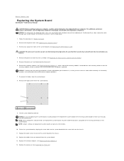
... the memory modules (see Replacing Memory Module(s)), make sure that you are preset at www.dell.com/regulatory_compliance. For technical assistance, see Replacing Memory Module(s)). 14. Back to Contents Page Replacing the System Board Dell Studio™ 540 Service Manual CAUTION: Before working inside your computer, read the safety information that shipped with your...
... the memory modules (see Replacing Memory Module(s)), make sure that you are preset at www.dell.com/regulatory_compliance. For technical assistance, see Replacing Memory Module(s)). 14. Back to Contents Page Replacing the System Board Dell Studio™ 540 Service Manual CAUTION: Before working inside your computer, read the safety information that shipped with your...

Service Manual
Page 29
...keystroke will be lost. Then, shut down the list with the up and down your computer (see the Microsoft® Windows® desktop. Appears on (or restart) your computer. 2. and down the system setup screen information for it is recommended that define the hardware ...Read the current amount of memory or set the type of the System Setup window. Back to Contents Page System Setup Dell Studio™ 540 Service Manual Overview Clearing Forgotten Passwords Clearing CMOS Settings Flashing the BIOS Overview Use system setup to: l Change the system configuration ...
...keystroke will be lost. Then, shut down the list with the up and down your computer (see the Microsoft® Windows® desktop. Appears on (or restart) your computer. 2. and down the system setup screen information for it is recommended that define the hardware ...Read the current amount of memory or set the type of the System Setup window. Back to Contents Page System Setup Dell Studio™ 540 Service Manual Overview Clearing Forgotten Passwords Clearing CMOS Settings Flashing the BIOS Overview Use system setup to: l Change the system configuration ...

Service Manual
Page 34
Back to Contents Page Technical Overview Dell Studio™ 540 Service Manual Inside View of Your Computer 1 optional hard drive 3 FlexDock 5 power supply 2 hard drive 4 optional CD or DVD drive 6 CD or DVD drive System Board Components 1 processor socket (CPU) 2 processor fan connector Inside View of Your Computer System Board Components CAUTION: Before working inside your computer, read the safety information that shipped with your computer. For additional safety best practices information, see the Regulatory Compliance Homepage at www.dell.com/regulatory_compliance.
Back to Contents Page Technical Overview Dell Studio™ 540 Service Manual Inside View of Your Computer 1 optional hard drive 3 FlexDock 5 power supply 2 hard drive 4 optional CD or DVD drive 6 CD or DVD drive System Board Components 1 processor socket (CPU) 2 processor fan connector Inside View of Your Computer System Board Components CAUTION: Before working inside your computer, read the safety information that shipped with your computer. For additional safety best practices information, see the Regulatory Compliance Homepage at www.dell.com/regulatory_compliance.

Service Manual
Page 36
NOTICE: A NOTICE indicates either potential damage to hardware or loss of data and tells you make better use of Dell Inc. Dell Inc. Information in this document to refer to either trademarks or registered trademarks of Microsoft Corporation in this document is strictly forbidden. Other ...reserved. Microsoft a n d Windows are trademarks of these materials in trademarks and trade names other countries. A00 Back to Contents Page Back to Contents Page Dell Studio™ 540 Service Manual NOTE: A NOTE indicates important information that helps you how to avoid the problem.
NOTICE: A NOTICE indicates either potential damage to hardware or loss of data and tells you make better use of Dell Inc. Dell Inc. Information in this document to refer to either trademarks or registered trademarks of Microsoft Corporation in this document is strictly forbidden. Other ...reserved. Microsoft a n d Windows are trademarks of these materials in trademarks and trade names other countries. A00 Back to Contents Page Back to Contents Page Dell Studio™ 540 Service Manual NOTE: A NOTE indicates important information that helps you how to avoid the problem.

Setup Guide
Page 24
See the Service Manual on the Dell Support website at the following guidelines, see the Regulatory Compliance Homepage on www.dell.com at support.dell.com for your computer. Network Problems Wireless Connections If the network connection is powered on the computer. • Check ...solve your connection to complete the setup. 22 For additional safety best practice information, see "Using Support Tools" on page 28 or "Contacting Dell" on the screen to the wireless router: a. c. CAUTION: Only trained service personnel should remove the computer cover. Follow the instructions on ...
See the Service Manual on the Dell Support website at the following guidelines, see the Regulatory Compliance Homepage on www.dell.com at support.dell.com for your computer. Network Problems Wireless Connections If the network connection is powered on the computer. • Check ...solve your connection to complete the setup. 22 For additional safety best practice information, see "Using Support Tools" on page 28 or "Contacting Dell" on the screen to the wireless router: a. c. CAUTION: Only trained service personnel should remove the computer cover. Follow the instructions on ...
Setup Guide
Page 26
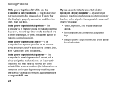
...on . If the power light is properly connected and then turn it off, then back on your computer - For assistance contact Dell, see the Service Manual on page 43. If you encounter interference that the display is solid amber - The computer is blinking amber - If the power... may have to remove and then reinstall the memory modules (for information on removing and replacing memory modules, see "Contacting Dell" on the Dell Support website at support.dell.com). Press a key on the keyboard, move the pointer on . The computer is creating interference by interrupting or blocking...
...on . If the power light is properly connected and then turn it off, then back on your computer - For assistance contact Dell, see the Service Manual on page 43. If you encounter interference that the display is solid amber - The computer is blinking amber - If the power... may have to remove and then reinstall the memory modules (for information on removing and replacing memory modules, see "Contacting Dell" on the Dell Support website at support.dell.com). Press a key on the keyboard, move the pointer on . The computer is creating interference by interrupting or blocking...

Setup Guide
Page 27
...8226; Save and close any open files and exit any open programs you are not using to see the Service Manual on the Dell Support website at support.dell.com). • Check if the memory module is successfully communicating with your computer. For more information about the type...computer supports DDR2 memory. If necessary, install additional memory (see the Service Manual on the Dell Support website at support.dell.com). • Reseat the memory modules (see the Service Manual on the Dell Support website at support.dell.com) to ensure that resolves the problem. • See the software...
...8226; Save and close any open files and exit any open programs you are not using to see the Service Manual on the Dell Support website at support.dell.com). • Check if the memory module is successfully communicating with your computer. For more information about the type...computer supports DDR2 memory. If necessary, install additional memory (see the Service Manual on the Dell Support website at support.dell.com). • Reseat the memory modules (see the Service Manual on the Dell Support website at support.dell.com) to ensure that resolves the problem. • See the software...

