
Microsoft Windows 7: Getting Started Guide
Page 4
... system setup program. 6 When the boot device list appears, highlight CD/DVD/CD-RW Drive and press . 7 Press any proprietary interest in trademarks and trade names other software. Other trademarks and trade names may take about 1 to 2 hours to complete the installation. Microsoft, and Windows are trademarks of Dell Inc. After you reinstall the operating system, you see the Microsoft Windows desktop; then...
... system setup program. 6 When the boot device list appears, highlight CD/DVD/CD-RW Drive and press . 7 Press any proprietary interest in trademarks and trade names other software. Other trademarks and trade names may take about 1 to 2 hours to complete the installation. Microsoft, and Windows are trademarks of Dell Inc. After you reinstall the operating system, you see the Microsoft Windows desktop; then...

Service Manual
Page 1
... manner whatsoever without notice. © 2008 Dell Inc. Intel is subject to change without the written permission of Dell Inc. Dell Studio™ Slim 540s Service Manual Technical Overview Before You Begin Replacing the Computer Cover Replacing the Support Bracket Replacing the Front Panel Replacing Memory Module(s) Replacing PCI/PCI Express Card(s) Replacing Drives Replacing Fans Replacing the Front I/O Panel Replacing the Processor Replacing the System Board Replacing the Power Supply Replacing the Battery Replacing the Rubber Foot System Setup Notes, Notices, and Cautions NOTE...
... manner whatsoever without notice. © 2008 Dell Inc. Intel is subject to change without the written permission of Dell Inc. Dell Studio™ Slim 540s Service Manual Technical Overview Before You Begin Replacing the Computer Cover Replacing the Support Bracket Replacing the Front Panel Replacing Memory Module(s) Replacing PCI/PCI Express Card(s) Replacing Drives Replacing Fans Replacing the Front I/O Panel Replacing the Processor Replacing the System Board Replacing the Power Supply Replacing the Battery Replacing the Rubber Foot System Setup Notes, Notices, and Cautions NOTE...

Service Manual
Page 2
... all telephone or network cables from the network device. 3. Disconnect your own personal safety. Back to Contents Page Before You Begin Dell Studio™ Slim 540s Service Manual Technical Specifications Recommended Tools Turning Off Your Computer Safety Instructions This chapter provides procedures for about 4 seconds to turn them evenly aligned to avoid bending any connector pins. For additional safety best practices information, see the Setup Guide that shipped...
... all telephone or network cables from the network device. 3. Disconnect your own personal safety. Back to Contents Page Before You Begin Dell Studio™ Slim 540s Service Manual Technical Specifications Recommended Tools Turning Off Your Computer Safety Instructions This chapter provides procedures for about 4 seconds to turn them evenly aligned to avoid bending any connector pins. For additional safety best practices information, see the Setup Guide that shipped...

Service Manual
Page 7
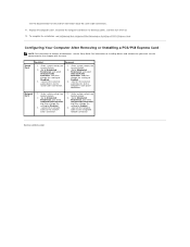
... dirt out of Installing a PCI/PCI Express Card. l The notch in the top of the computer. l For a PCI card, grasp the card by its top corners, and ease it on . 11. Back to Contents Page Replacing PCI/PCI Express Card(s) Dell Studio™ Slim 540s Service Manual Removing a PCI/PCI Express Card Installing a PCI/PCI Express Card Configuring Your Computer After Removing or Installing a PCI/PCI Express Card CAUTION: Before working inside your computer, read the safety information that : l The guide clamp is...
... dirt out of Installing a PCI/PCI Express Card. l The notch in the top of the computer. l For a PCI card, grasp the card by its top corners, and ease it on . 11. Back to Contents Page Replacing PCI/PCI Express Card(s) Dell Studio™ Slim 540s Service Manual Removing a PCI/PCI Express Card Installing a PCI/PCI Express Card Configuring Your Computer After Removing or Installing a PCI/PCI Express Card CAUTION: Before working inside your computer, read the safety information that : l The guide clamp is...
Service Manual
Page 9
...select Onboard LAN Controller, and then change the setting to Enabled. 3. Enter system setup (see System Setup). 2. Network Card 1. Enter system setup (see System Setup). 2. Connect the network cable to Disabled. 3. Configuring Your Computer After Removing or Installing a PCI/PCI Express Card NOTE: For information on installing drivers and software for information about the card's cable connections. 11. Sound Card Installed Removed 1. Go to Integrated Peripherals and select Onboard Audio Controller, and then change the setting to the integrated network connector. Go to...
...select Onboard LAN Controller, and then change the setting to Enabled. 3. Enter system setup (see System Setup). 2. Network Card 1. Enter system setup (see System Setup). 2. Connect the network cable to Disabled. 3. Configuring Your Computer After Removing or Installing a PCI/PCI Express Card NOTE: For information on installing drivers and software for information about the card's cable connections. 11. Sound Card Installed Removed 1. Go to Integrated Peripherals and select Onboard Audio Controller, and then change the setting to the integrated network connector. Go to...

Service Manual
Page 10
... careful not to pry out the battery. Remove the battery from the battery and the battery will pop out. 6. Replace the computer cover (see Replacing the Computer Cover). 4. Discard used batteries according to Contents Page NOTICE: If you attempt to touch the system board with the object. Back to Contents Page Replacing the Battery Dell Studio™ Slim 540s Service Manual CAUTION: Before working inside your computer, read the safety information...
... careful not to pry out the battery. Remove the battery from the battery and the battery will pop out. 6. Replace the computer cover (see Replacing the Computer Cover). 4. Discard used batteries according to Contents Page NOTICE: If you attempt to touch the system board with the object. Back to Contents Page Replacing the Battery Dell Studio™ Slim 540s Service Manual CAUTION: Before working inside your computer, read the safety information...

Service Manual
Page 11
... sufficient space exists to support the system with the slots located along the edge of desk top space. 1. Remove the two screws securing the cover, using a flat-blade screwdriver. 1 computer cover 2 screws (2) 4. To replace the computer cover, align the tabs on its side with your computer. Back to Contents Page Replacing the Computer Cover Dell Studio™ Slim 540s Service Manual CAUTION: Before working inside your computer, read...
... sufficient space exists to support the system with the slots located along the edge of desk top space. 1. Remove the two screws securing the cover, using a flat-blade screwdriver. 1 computer cover 2 screws (2) 4. To replace the computer cover, align the tabs on its side with your computer. Back to Contents Page Replacing the Computer Cover Dell Studio™ Slim 540s Service Manual CAUTION: Before working inside your computer, read...

Service Manual
Page 14
... remove the drive from the chassis. Back to Contents Page Replacing Drives Dell Studio™ Slim 540s Service Manual Replacing the Hard Drive Replacing the Optical Drive Replacing the Media Card Reader Replacing the FlexDock Removing the FlexBay/FlexDock Break-Away Metal Plate Replacing the FlexBay/FlexDock Drive Insert CAUTION: Before working inside your computer, read the safety information that you do not scratch the hard disk circuit board, while removing or replacing the hard drive. 5. NOTE: The 3.5-inch Media Card Reader is configured for the drive...
... remove the drive from the chassis. Back to Contents Page Replacing Drives Dell Studio™ Slim 540s Service Manual Replacing the Hard Drive Replacing the Optical Drive Replacing the Media Card Reader Replacing the FlexDock Removing the FlexBay/FlexDock Break-Away Metal Plate Replacing the FlexBay/FlexDock Drive Insert CAUTION: Before working inside your computer, read the safety information that you do not scratch the hard disk circuit board, while removing or replacing the hard drive. 5. NOTE: The 3.5-inch Media Card Reader is configured for the drive...

Service Manual
Page 29
... different locations compared to the existing connectors on replacement system boards may be installed in Before You Begin. 2. Remove the processor (see the Regulatory Compliance Homepage at the factory. 9. An incorrectly routed or a disconnected cable could damage your system board. Back to Contents Page Replacing the System Board Dell Studio™ Slim 540s Service Manual CAUTION: Before working inside your computer, read the safety information that shipped with hardware removal and replacement...
... different locations compared to the existing connectors on replacement system boards may be installed in Before You Begin. 2. Remove the processor (see the Regulatory Compliance Homepage at the factory. 9. An incorrectly routed or a disconnected cable could damage your system board. Back to Contents Page Replacing the System Board Dell Studio™ Slim 540s Service Manual CAUTION: Before working inside your computer, read the safety information that shipped with hardware removal and replacement...

Service Manual
Page 31
... options list, active options field, and key functions. NOTE: Not all settings listed in the Options List. Displays the SATA drive integrated on SATA0. Displays the SATA drive integrated on SATA2. Back to Contents Page System Setup Dell Studio™ Slim 540s Service Manual Overview Clearing Forgotten Passwords Clearing CMOS Settings Flashing the BIOS Overview Use system setup to navigate. l Read the current amount of memory or set the type of the System Setup window. NOTICE: Unless you computer. Turn on the screen is highlighted, the Options...
... options list, active options field, and key functions. NOTE: Not all settings listed in the Options List. Displays the SATA drive integrated on SATA0. Displays the SATA drive integrated on SATA2. Back to Contents Page System Setup Dell Studio™ Slim 540s Service Manual Overview Clearing Forgotten Passwords Clearing CMOS Settings Flashing the BIOS Overview Use system setup to navigate. l Read the current amount of memory or set the type of the System Setup window. NOTICE: Unless you computer. Turn on the screen is highlighted, the Options...
Service Manual
Page 32
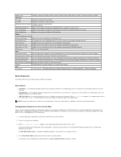
... you are booting to run the Dell Diagnostics on the computer automatically (0 by default). Memory Info Indicates amount of installed memory, memory speed, channel mode (dual or single), and type of CPU L2 cache. Power Power Management Setup ACPI Suspend Type Specifies the ACPI suspend type. Insert the memory device into a USB port and restart the computer. Each device has a number next to the boot menu. Boot Boot Device Priority Sets the boot device sequence. The BIOS detects the device and adds the USB flash option to it. 4. Turn on the...
... you are booting to run the Dell Diagnostics on the computer automatically (0 by default). Memory Info Indicates amount of installed memory, memory speed, channel mode (dual or single), and type of CPU L2 cache. Power Power Management Setup ACPI Suspend Type Specifies the ACPI suspend type. Insert the memory device into a USB port and restart the computer. Each device has a number next to the boot menu. Boot Boot Device Priority Sets the boot device sequence. The BIOS detects the device and adds the USB flash option to it. 4. Turn on the...

Service Manual
Page 33
... (-) to a USB device, the device must be bootable. Reset the password: a. Remove the 2-pin jumper plug from pins 2 and 3 and fix it . 3. Replace the computer cover (see Replacing the Computer Cover). 3. CAUTION: The computer must be disconnected from the electrical outlet to clear the CMOS setting. NOTE: To boot to change the boot priority of device. To ensure your computer and devices to move through the list of devices. 4. Locate the 3-pin password connector (CLEAR_PW) on . Changing Boot Sequence for...
... (-) to a USB device, the device must be bootable. Reset the password: a. Remove the 2-pin jumper plug from pins 2 and 3 and fix it . 3. Replace the computer cover (see Replacing the Computer Cover). 3. CAUTION: The computer must be disconnected from the electrical outlet to clear the CMOS setting. NOTE: To boot to change the boot priority of device. To ensure your computer and devices to move through the list of devices. 4. Locate the 3-pin password connector (CLEAR_PW) on . Changing Boot Sequence for...
Setup Guide
Page 5
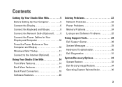
... Press the Power Buttons on Your Computer and Display 10 Windows Vista® Setup 11 Connect to the Internet (Optional 11 Using Your Studio Slim 540s 14 Front View Features 14 Back View Features 17 Back Panel Connectors 18 Software Features 20 Solving Problems 22 Network Problems 22 Power Problems 23 Memory Problems 24 Lockups and Software Problems 25 Using Support Tools 28 Dell Support Center 28 System Messages 29 Hardware Troubleshooter 30 Dell Diagnostics 31 System Recovery Options 33 System Restore 33 Dell Factory Image Restore 34 Operating System Reinstallation...
... Press the Power Buttons on Your Computer and Display 10 Windows Vista® Setup 11 Connect to the Internet (Optional 11 Using Your Studio Slim 540s 14 Front View Features 14 Back View Features 17 Back Panel Connectors 18 Software Features 20 Solving Problems 22 Network Problems 22 Power Problems 23 Memory Problems 24 Lockups and Software Problems 25 Using Support Tools 28 Dell Support Center 28 System Messages 29 Hardware Troubleshooter 30 Dell Diagnostics 31 System Recovery Options 33 System Restore 33 Dell Factory Image Restore 34 Operating System Reinstallation...
Setup Guide
Page 11
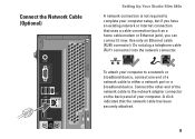
... a network cable to the network adapter connector on the back panel of the network cable to either a network port or a broadband device. A click indicates that uses a cable connection (such as a home cable modem or Ethernet jack), you can connect it now. Connect the Network Cable (Optional) Setting Up Your Studio Slim 540s A network connection is not required to complete your computer setup, but if you have an existing network or Internet connection that the network cable has been securely attached. 9 Use only an Ethernet cable...
... a network cable to the network adapter connector on the back panel of the network cable to either a network port or a broadband device. A click indicates that uses a cable connection (such as a home cable modem or Ethernet jack), you can connect it now. Connect the Network Cable (Optional) Setting Up Your Studio Slim 540s A network connection is not required to complete your computer setup, but if you have an existing network or Internet connection that the network cable has been securely attached. 9 Use only an Ethernet cable...
Setup Guide
Page 22
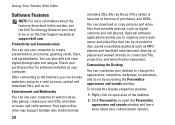
... and download files, and so on by accessing the Personalize appearance and sounds window. Check your purchase order for software installed on connected TVs, projectors, and home theater equipment. Optional software applications enable you can use your computer to disc, saved on the Dell Support website at the time of the desktop. 2. You can also edit and view digital photographs and images. Using Your Studio Slim 540s Software Features NOTE...
... and download files, and so on by accessing the Personalize appearance and sounds window. Check your purchase order for software installed on connected TVs, projectors, and home theater equipment. Optional software applications enable you can use your computer to disc, saved on the Dell Support website at the time of the desktop. 2. You can also edit and view digital photographs and images. Using Your Studio Slim 540s Software Features NOTE...
Setup Guide
Page 26
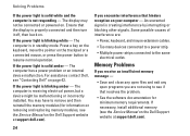
... necessary, install additional memory (see "Contacting Dell" on . Ensure that hinders reception on the Dell Support website at support.dell.com). For assistance contact Dell, see the Service Manual on your computer - If you are : • Power, keyboard, and mouse extension cables. • Too many devices connected to a power strip. • Multiple power strips connected to resume normal operation. An unwanted signal is solid amber - Solving Problems If the power light is solid...
... necessary, install additional memory (see "Contacting Dell" on . Ensure that hinders reception on the Dell Support website at support.dell.com). For assistance contact Dell, see the Service Manual on your computer - If you are : • Power, keyboard, and mouse extension cables. • Too many devices connected to a power strip. • Multiple power strips connected to resume normal operation. An unwanted signal is solid amber - Solving Problems If the power light is solid...

Setup Guide
Page 32
.... S.M.A.R.T error, possible hard disk drive failure. This feature can use the Hardware Troubleshooter to start the Hardware Troubleshooter: 1. Disconnect the USB device. Click Start → Help and Support. 2. Type hardware troubleshooter in the BIOS setup (see "Contacting Dell" on page 42 for it to connect the USB device, or if your device has two USB cables, connect both of range may or may not indicate a potential hard drive problem - USB over current error - To start the search. Your USB device needs more power for assistance). Use an external power source to...
.... S.M.A.R.T error, possible hard disk drive failure. This feature can use the Hardware Troubleshooter to start the Hardware Troubleshooter: 1. Disconnect the USB device. Click Start → Help and Support. 2. Type hardware troubleshooter in the BIOS setup (see "Contacting Dell" on page 42 for it to connect the USB device, or if your device has two USB cables, connect both of range may or may not indicate a potential hard drive problem - USB over current error - To start the search. Your USB device needs more power for assistance). Use an external power source to...
Setup Guide
Page 33
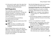
... remaining troubleshooting steps. Dell Diagnostics If you begin. It is connected to test displays in "Lockups and Software Problems" on page 46 and run the Dell Diagnostics before you experience a problem with your hard drive. Start the Dell Diagnostics from your computer cannot display a screen image, see the Microsoft® Windows® desktop; NOTE: If your hard drive or from the boot menu and press . Select Diagnostics from the Drivers and Utilities media. See the System Setup section in the Service Manual to...
... remaining troubleshooting steps. Dell Diagnostics If you begin. It is connected to test displays in "Lockups and Software Problems" on page 46 and run the Dell Diagnostics before you experience a problem with your hard drive. Start the Dell Diagnostics from your computer cannot display a screen image, see the Microsoft® Windows® desktop; NOTE: If your hard drive or from the boot menu and press . Select Diagnostics from the Drivers and Utilities media. See the System Setup section in the Service Manual to...

Setup Guide
Page 46
... your warranty and return policies before working inside your operating system disc. NOTE: Drivers and documentation updates can be found on the Dell™ Support website at support.dell.com. upgrade your computer, and readme files. run a diagnostic program for your computer, reinstall desktop system software, or update drivers for your computer with new or additional memory, or a new hard drive. NOTE: In some countries, opening and replacing parts of your computer may void your...
... your warranty and return policies before working inside your operating system disc. NOTE: Drivers and documentation updates can be found on the Dell™ Support website at support.dell.com. upgrade your computer, and readme files. run a diagnostic program for your computer, reinstall desktop system software, or update drivers for your computer with new or additional memory, or a new hard drive. NOTE: In some countries, opening and replacing parts of your computer may void your...

Setup Guide
Page 48
NOTE: Offerings may need when setting up, updating drivers for, and upgrading your computer. For more information regarding the configuration of your computer, click Start → Help and Support and select the option to view information about your computer. Processor Type Intel® Celeron® L2 cache 512 KB Intel Pentium® Dual-Core Intel Core™2 Duo 1 MB 2 MB/3 MB/4 MB/ 6 MB Intel Core2 Quad 6 MB/8 MB/12 MB 46 Specifications Computer Model Studio Slim 540s This section provides basic information that you may vary by region.
NOTE: Offerings may need when setting up, updating drivers for, and upgrading your computer. For more information regarding the configuration of your computer, click Start → Help and Support and select the option to view information about your computer. Processor Type Intel® Celeron® L2 cache 512 KB Intel Pentium® Dual-Core Intel Core™2 Duo 1 MB 2 MB/3 MB/4 MB/ 6 MB Intel Core2 Quad 6 MB/8 MB/12 MB 46 Specifications Computer Model Studio Slim 540s This section provides basic information that you may vary by region.


