Service Manual
Page 3
... the PCIe expansion card...40 Installing the PCIe expansion card...42 Optional card...44 Removing the optional card...44 Installing the optional card...46 Power supply unit...48 Removing power supply unit...48 Contents 3 Contents 1 Working on your computer...5 Safety instructions...5 Turning off your computer...6 2 Technology and components...7 HDMI 1.4...7 USB features...7 3 Removing and installing...
... the PCIe expansion card...40 Installing the PCIe expansion card...42 Optional card...44 Removing the optional card...44 Installing the optional card...46 Power supply unit...48 Removing power supply unit...48 Contents 3 Contents 1 Working on your computer...5 Safety instructions...5 Turning off your computer...6 2 Technology and components...7 HDMI 1.4...7 USB features...7 3 Removing and installing...
Service Manual
Page 4
ePSA diagnostics 79 Running the ePSA Diagnostics...79 Diagnostics...79 Diagnostic error messages...80 System error messages...82 5 Getting help...84 Contacting Dell...84 4 Contents Installing power supply unit...52 Cooling shroud...56 Removing the cooling shroud...56 Installing the cooling shroud...58 Heat sink assembly...60 Removing the heat sink assembly...60 ...
ePSA diagnostics 79 Running the ePSA Diagnostics...79 Diagnostics...79 Diagnostic error messages...80 System error messages...82 5 Getting help...84 Contacting Dell...84 4 Contents Installing power supply unit...52 Cooling shroud...56 Removing the cooling shroud...56 Installing the cooling shroud...58 Heat sink assembly...60 Removing the heat sink assembly...60 ...

Service Manual
Page 48
4. Remove the: a) Cover b) Cooling shroud 3. Install the: a) Cover 5. Follow the procedure in After working inside your computer. 2. Power supply unit Removing power supply unit 1. Follow the procedure in Before working inside your computer. Removing the Power supply unit (PSU): a) Disconnect the PSU cables from the connectors on the system board. 48 Removing and installing components
4. Remove the: a) Cover b) Cooling shroud 3. Install the: a) Cover 5. Follow the procedure in After working inside your computer. 2. Power supply unit Removing power supply unit 1. Follow the procedure in Before working inside your computer. Removing the Power supply unit (PSU): a) Disconnect the PSU cables from the connectors on the system board. 48 Removing and installing components

Service Manual
Page 52
Insert the power supply unit (PSU) into the PSU slot and slide it toward the back of the computer until it clicks into place. 52 Removing and installing components Installing power supply unit 1.
Insert the power supply unit (PSU) into the PSU slot and slide it toward the back of the computer until it clicks into place. 52 Removing and installing components Installing power supply unit 1.

Service Manual
Page 69
Unroute and disconnect the hard drive power cable, hard drive data cable, optical drive power cable, power supply unit cable [1, 2, 3, 4, 5]. h) Heat sink assembly i) Processor 3. Removing and installing components 69 To remove I/O panel cover: a) Disconnect the cable from the system board [1] b) Remove the one (6-32x6.35) screw that secures the I /O panel cover [3]. 4. c) Slide the I /O panel cover to the computer [2].
Unroute and disconnect the hard drive power cable, hard drive data cable, optical drive power cable, power supply unit cable [1, 2, 3, 4, 5]. h) Heat sink assembly i) Processor 3. Removing and installing components 69 To remove I/O panel cover: a) Disconnect the cable from the system board [1] b) Remove the one (6-32x6.35) screw that secures the I /O panel cover [3]. 4. c) Slide the I /O panel cover to the computer [2].

Service Manual
Page 76
3. Connect the hard drive, optical drive, power supply unit cable and speaker cables to the system board. 76 Removing and installing components
3. Connect the hard drive, optical drive, power supply unit cable and speaker cables to the system board. 76 Removing and installing components

Setup and specifications guide
Page 3
...specifications...12 Communications...12 Video...12 Audio...14 Storage...14 Processor specifications...14 Storage combinations...15 System board connectors...15 Power supply...15 Security hardware...16 Regulatory and Environmental Compliance...16 4 System setup...17 BIOS overview...17 General screen options......screen options...19 Secure Boot screen options...21 Intel Software Guard Extensions screen options...21 Performance screen options...21 Power Management screen options...22 POST Behavior screen options...23 Virtualization support screen options...23 Wireless screen options...23 Maintenance...
...specifications...12 Communications...12 Video...12 Audio...14 Storage...14 Processor specifications...14 Storage combinations...15 System board connectors...15 Power supply...15 Security hardware...16 Regulatory and Environmental Compliance...16 4 System setup...17 BIOS overview...17 General screen options......screen options...19 Secure Boot screen options...21 Intel Software Guard Extensions screen options...21 Performance screen options...21 Power Management screen options...22 POST Behavior screen options...23 Virtualization support screen options...23 Wireless screen options...23 Maintenance...
Setup and specifications guide
Page 9
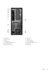
Microphone port 5. Power connector port 13. Expansion card slots 10. Padlock ring 14. Network port Chassis 9 USB 2.0 ports (4) 9. Power supply diagnostics button 11. Line-out port 4. HDMI port 6. Service tag label 8. Power supply diagnostics light 12. 1. Line-in port 3. VGA port 7. Kensington security slot 2.
Microphone port 5. Power connector port 13. Expansion card slots 10. Padlock ring 14. Network port Chassis 9 USB 2.0 ports (4) 9. Power supply diagnostics button 11. Line-out port 4. HDMI port 6. Service tag label 8. Power supply diagnostics light 12. 1. Line-in port 3. VGA port 7. Kensington security slot 2.

Setup and specifications guide
Page 10
...; Memory • Port and connector specifications • Communications • Video • Audio • Storage • Processor specifications • Storage combinations • System board connectors • Power supply • Security hardware • Regulatory and Environmental Compliance Dimensions and weight Table 2. Dimensions and weight Height Width Depth Weight 14.7 inch (373.7 mm) 6.3 inch (160...
...; Memory • Port and connector specifications • Communications • Video • Audio • Storage • Processor specifications • Storage combinations • System board connectors • Power supply • Security hardware • Regulatory and Environmental Compliance Dimensions and weight Table 2. Dimensions and weight Height Width Depth Weight 14.7 inch (373.7 mm) 6.3 inch (160...

Setup and specifications guide
Page 15
... only. Storage combinations Type M.2 Drive + SATA Form factor M.2 128GB Solid State Drive+ 1TB 7200 rpm Hard Drive System board connectors Table 13. System specifications 15 Power supply Input Voltage Input current (maximum) 100-240 VAC, 50-60 Hz • 290 W PSU (APFC Full range) • 290 W PSU (EPA Bronze) • 365 W PSU... Core I5-9400 9th Generation I5-9400 processor (9 MB Cache, up to 6Gb/s) PCIe X16 (1) PCIe X1 (2) PCI (1) NOTE: PCI slot support on TPM sku Power supply Table 14.
... only. Storage combinations Type M.2 Drive + SATA Form factor M.2 128GB Solid State Drive+ 1TB 7200 rpm Hard Drive System board connectors Table 13. System specifications 15 Power supply Input Voltage Input current (maximum) 100-240 VAC, 50-60 Hz • 290 W PSU (APFC Full range) • 290 W PSU (EPA Bronze) • 365 W PSU... Core I5-9400 9th Generation I5-9400 processor (9 MB Cache, up to 6Gb/s) PCIe X16 (1) PCIe X1 (2) PCI (1) NOTE: PCI slot support on TPM sku Power supply Table 14.


