Product Manual
Page 4
...Regional Voltage 2-1 Connect to Mains Power 2-3 Set the Handle Position 2-4 Power On and Standby 2-5 Warm-Up the Product 2-6 Configure the Product 2-6 Input Module and Relay Card Installation 2-7 Set Up Security 2-10 3 Input and Channel Configuration 3-1 Introduction ...3-1 Input Wiring...3-1 The Universal Input Module 3-1 Wiring Safety and Considerations 3-2 3-Wire and 4-Wire Sense Input Configuration 3-3 Input Types and Wiring Diagrams 3-5 Input Wiring Instructions 3-6 Channel Configuration 3-7 About Channel Numbers 3-7 Basic Channel Operations 3-10 Open the Channel Setup...
...Regional Voltage 2-1 Connect to Mains Power 2-3 Set the Handle Position 2-4 Power On and Standby 2-5 Warm-Up the Product 2-6 Configure the Product 2-6 Input Module and Relay Card Installation 2-7 Set Up Security 2-10 3 Input and Channel Configuration 3-1 Introduction ...3-1 Input Wiring...3-1 The Universal Input Module 3-1 Wiring Safety and Considerations 3-2 3-Wire and 4-Wire Sense Input Configuration 3-3 Input Types and Wiring Diagrams 3-5 Input Wiring Instructions 3-6 Channel Configuration 3-7 About Channel Numbers 3-7 Basic Channel Operations 3-10 Open the Channel Setup...

Product Manual
Page 5
... the Setup CSV File 4-17 How to Read the Data CSV File 4-19 5 DMM Operation 5-1 Introduction ...5-1 About the DMM Function 5-1 Input Type Selection and Range Adjustment 5-2 More Functions (PT385 or PT392 5-2 Relative Measurements 5-2 Graph the Measurements 5-3 Measurement Statistics 5-4 6 Maintenance and Care 6-1 Introduction ...6-1 Clean the Product 6-1 Replace the Fuse 6-1 Memory Reset and Factory Reset 6-2 Firmware Update 6-3 iii MyFlukeStore Shop for Fluke...
... the Setup CSV File 4-17 How to Read the Data CSV File 4-19 5 DMM Operation 5-1 Introduction ...5-1 About the DMM Function 5-1 Input Type Selection and Range Adjustment 5-2 More Functions (PT385 or PT392 5-2 Relative Measurements 5-2 Graph the Measurements 5-3 Measurement Statistics 5-4 6 Maintenance and Care 6-1 Introduction ...6-1 Clean the Product 6-1 Replace the Fuse 6-1 Memory Reset and Factory Reset 6-2 Firmware Update 6-3 iii MyFlukeStore Shop for Fluke...
Product Manual
Page 7
... Chart 7-17 v MyFlukeStore Shop for Fluke products online at: www. .com 1.877.766.5412 Sy mbols...1-7 2-1. Thermistor Channel Setup 3-21 3-9. Fuses ...2-1 2-2. Resistance Channel Configuration 3-18 3-6. Fuses ...6-1 6-2. User-Replaceable Parts and Accessories 6-5 7-1. Rear-Panel Features 1-5 1-3. The Scan Menu ...4-2 4-2. Comparison of the Memory Clear Functions 6-2 6-3. Scan Sample Rates 4-8 4-4. Instrument Setup Menu 2-6 3-1. Scan Data Memory Usage 4-15 5-1. Front-Panel Features 1-3 1-2. Totalizer Channel Configuration 3-25 3-11.
... Chart 7-17 v MyFlukeStore Shop for Fluke products online at: www. .com 1.877.766.5412 Sy mbols...1-7 2-1. Thermistor Channel Setup 3-21 3-9. Fuses ...2-1 2-2. Resistance Channel Configuration 3-18 3-6. Fuses ...6-1 6-2. User-Replaceable Parts and Accessories 6-5 7-1. Rear-Panel Features 1-5 1-3. The Scan Menu ...4-2 4-2. Comparison of the Memory Clear Functions 6-2 6-3. Scan Sample Rates 4-8 4-4. Instrument Setup Menu 2-6 3-1. Scan Data Memory Usage 4-15 5-1. Front-Panel Features 1-3 1-2. Totalizer Channel Configuration 3-25 3-11.
Product Manual
Page 9
... data. • Monitor - Users can be viewed on the display in progress or inactive. fChapter 1 Product Overview and Specifications Introduction This chapter supplies information about the Product, the manual set, safety information, contact information, and specifications. Product Overview The Fluke 2638A HYDRA Series III Data Acquisition Unit (the Product or Instrument) is in a spreadsheet format along with a softkey to -peak, and rate...
... data. • Monitor - Users can be viewed on the display in progress or inactive. fChapter 1 Product Overview and Specifications Introduction This chapter supplies information about the Product, the manual set, safety information, contact information, and specifications. Product Overview The Fluke 2638A HYDRA Series III Data Acquisition Unit (the Product or Instrument) is in a spreadsheet format along with a softkey to -peak, and rate...
Product Manual
Page 12
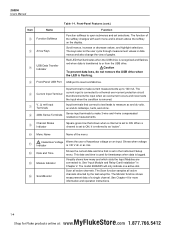
2638A Users Manual Item Name Function Softkeys Arrow Keys USB Data Transfer Indicator Table 1-1. The keys also let the user cycle through measurement values in data menus and also change the view of hazardous voltage on the display. WCaution To prevent data loss, do not remove the USB drive when the LED is flashing. Front-Panel USB Port USB port to . Input terminal to make 3-wire and...
2638A Users Manual Item Name Function Softkeys Arrow Keys USB Data Transfer Indicator Table 1-1. The keys also let the user cycle through measurement values in data menus and also change the view of hazardous voltage on the display. WCaution To prevent data loss, do not remove the USB drive when the LED is flashing. Front-Panel USB Port USB port to . Input terminal to make 3-wire and...

Product Manual
Page 13
... a screenshot of the display. Configure and verify channels. Channel Setup is the default menu that lets the user quickly configure and make measurements with the front-panel DMM can be recorded. Menu contains many user-configurable settings to input numerical values when prompted. See Chapter 3 for Fluke products online at: www. .com 1.877.766.5412 See "Set the Regional Voltage" in Chapter 2. When...
... a screenshot of the display. Configure and verify channels. Channel Setup is the default menu that lets the user quickly configure and make measurements with the front-panel DMM can be recorded. Menu contains many user-configurable settings to input numerical values when prompted. See Chapter 3 for Fluke products online at: www. .com 1.877.766.5412 See "Set the Regional Voltage" in Chapter 2. When...
Product Manual
Page 14
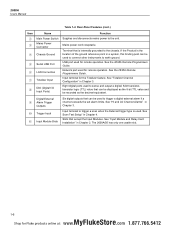
... equivalent. Network port used to connect other instruments to the unit. See "Totalizer Channel Configuration" in Chapter 4. Rear-Panel Features (cont.) Item Name Main Power Switch Mains Power Connector Chassis Ground Serial USB Port LAN Connection Totalizer Input DIO (Digital I/O Input Ports) Function Supplies and disconnects mains power to earth ground. See the 2638A Remote Programmers Guide. Input terminal for Fluke products online...
... equivalent. Network port used to connect other instruments to the unit. See "Totalizer Channel Configuration" in Chapter 4. Rear-Panel Features (cont.) Item Name Main Power Switch Mains Power Connector Chassis Ground Serial USB Port LAN Connection Totalizer Input DIO (Digital I/O Input Ports) Function Supplies and disconnects mains power to earth ground. See the 2638A Remote Programmers Guide. Input terminal for Fluke products online...
Product Manual
Page 15
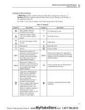
... circuits connected directly to utilization points (socket outlets and similar points) of the building's low-voltage MAINS installation. This product complies with the requirements of the building's low-voltage MAINS installation. Table 1-3. A Caution identifies conditions and procedures that are dangerous to the user. See manual. Symbols Symbol Description W Risk of symbols used in the WEEE Directive Annex I, this product as category 9 "Monitoring and Control...
... circuits connected directly to utilization points (socket outlets and similar points) of the building's low-voltage MAINS installation. This product complies with the requirements of the building's low-voltage MAINS installation. Table 1-3. A Caution identifies conditions and procedures that are dangerous to the user. See manual. Symbols Symbol Description W Risk of symbols used in the WEEE Directive Annex I, this product as category 9 "Monitoring and Control...

Product Manual
Page 16
... the protection supplied by the Product can be compromised. • Examine the case before you use test leads if they are damaged. Look for the Product. • Replace the mains power cord if the insulation is connected to the mains power cord is blocked. • Use only correct measurement category (CAT), voltage, and amperage rated probes, test leads, and adapters for Fluke products online...
... the protection supplied by the Product can be compromised. • Examine the case before you use test leads if they are damaged. Look for the Product. • Replace the mains power cord if the insulation is connected to the mains power cord is blocked. • Use only correct measurement category (CAT), voltage, and amperage rated probes, test leads, and adapters for Fluke products online...

Product Manual
Page 18
... 2 supplies information and instructions on how to troubleshoot the Product. 2638A Users Manual About this Product. The Product Manual Set The Product manual set up and configure the Product for Fluke products online at: www. .com 1.877.766.5412 The Users Manual is translated into many languages. • The 2638A Safety Information is translated into many languages. • The 2638A Remote Programmers Guide contains information on error messages...
... 2 supplies information and instructions on how to troubleshoot the Product. 2638A Users Manual About this Product. The Product Manual Set The Product manual set up and configure the Product for Fluke products online at: www. .com 1.877.766.5412 The Users Manual is translated into many languages. • The 2638A Safety Information is translated into many languages. • The 2638A Remote Programmers Guide contains information on error messages...
Product Manual
Page 19
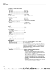
2638A Users Manual General Specifications Mains Voltage 100 V Setting 90 V to 110 V 120 V Setting 108 V to 132 V 220 V Setting 198 V to 242 V 240 V Setting 216 V to 264 V Frequency 47 Hz to 440 Hz Power Consumption 36 VA peak (24 W average) Environment Temperature Operating 0 °C to 50 °C Full accuracy 18 °C to 28 °C Storage 20 °C to 70 °C Warm-up 1 hour to full accuracy specifications Relative Humidity (non-condensing) Operating 0 °C to 28 °C
2638A Users Manual General Specifications Mains Voltage 100 V Setting 90 V to 110 V 120 V Setting 108 V to 132 V 220 V Setting 198 V to 242 V 240 V Setting 216 V to 264 V Frequency 47 Hz to 440 Hz Power Consumption 36 VA peak (24 W average) Environment Temperature Operating 0 °C to 50 °C Full accuracy 18 °C to 28 °C Storage 20 °C to 70 °C Warm-up 1 hour to full accuracy specifications Relative Humidity (non-condensing) Operating 0 °C to 28 °C

Product Manual
Page 33
... a protective earth ground. WXWarning To prevent possible electrical shock, fire, or personal injury: • Use only the mains power cord and connector approved for the voltage and plug configuration in your country and rated for Fluke products online at: www. .com 1.877.766.5412 Disruption of wear. • Make sure the ground conductor in the mains power cord is connected to the mains power cord is...
... a protective earth ground. WXWarning To prevent possible electrical shock, fire, or personal injury: • Use only the mains power cord and connector approved for the voltage and plug configuration in your country and rated for Fluke products online at: www. .com 1.877.766.5412 Disruption of wear. • Make sure the ground conductor in the mains power cord is connected to the mains power cord is...
Product Manual
Page 36
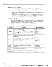
... has been turned off . Shows the firmware version installed, model number, and serial number Date Changes the date and date format shown on the front panel. This will ensure the best performance to English. Instrument Setup Menu Menu Item Language Firmware Description Changes the display language. This temporarily resets the language to the specification listed in the Instrument Setup menu. This date is also used for Fluke products online...
... has been turned off . Shows the firmware version installed, model number, and serial number Date Changes the date and date format shown on the front panel. This will ensure the best performance to English. Instrument Setup Menu Menu Item Language Firmware Description Changes the display language. This temporarily resets the language to the specification listed in the Instrument Setup menu. This date is also used for Fluke products online...
Product Manual
Page 37
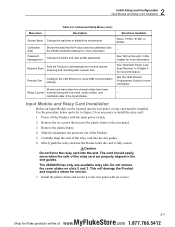
... along with the main power switch. 2. Do not remove the cover plates on and resume scanning and recording after a power loss. Change the Admin and User profile passwords. Resume Scan Sets the Product to install the relay card: 1. 2 Initial Setup and Configuration Input Module and Relay Card Installation Table 2-2. See "Automatic Power Loss Scan Resume" in Chapter 4 for service. 7. Carefully align the rails...
... along with the main power switch. 2. Do not remove the cover plates on and resume scanning and recording after a power loss. Change the Admin and User profile passwords. Resume Scan Sets the Product to install the relay card: 1. 2 Initial Setup and Configuration Input Module and Relay Card Installation Table 2-2. See "Automatic Power Loss Scan Resume" in Chapter 4 for service. 7. Carefully align the rails...

Product Manual
Page 46
... does not turn . 4. 2638A Users Manual Input Wiring Instructions Use the procedure below and refer to Figure 3-1 for Fluke products online at the rear of the Product until it latches in place. 8. Power on the left side of the Product. 3. For instructions on how to configure the various input types, see "Channel Configuration" on page 3-7. 3-6 MyFlukeStore Shop for instructions on how to wire a 2-wire, 3-wire, or 4-wire input...
... does not turn . 4. 2638A Users Manual Input Wiring Instructions Use the procedure below and refer to Figure 3-1 for Fluke products online at the rear of the Product until it latches in place. 8. Power on the left side of the Product. 3. For instructions on how to configure the various input types, see "Channel Configuration" on page 3-7. 3-6 MyFlukeStore Shop for instructions on how to wire a 2-wire, 3-wire, or 4-wire input...

Product Manual
Page 64
... Channel Setup or by remote command. It is shown on the display and the decimal equivalent will be manually reset at : www. .com 1.877.766.5412 Without a filter the Product detects multiple closures that can detect bounce on page 3-11). 4. 2638A Users Manual 3. The...reset to the ground (GND). In read /reset. The totalizer count is not reset when it is viewed with the Edit channel function of the signal transitions from high to low or a contact closes to 0 when it . Set channel 401 to ON (see "Set Channels to the data file. Debounce (600 Hz) can be turned on the rear panel...
... Channel Setup or by remote command. It is shown on the display and the decimal equivalent will be manually reset at : www. .com 1.877.766.5412 Without a filter the Product detects multiple closures that can detect bounce on page 3-11). 4. 2638A Users Manual 3. The...reset to the ground (GND). In read /reset. The totalizer count is not reset when it is viewed with the Edit channel function of the signal transitions from high to low or a contact closes to 0 when it . Set channel 401 to ON (see "Set Channels to the data file. Debounce (600 Hz) can be turned on the rear panel...
Product Manual
Page 79
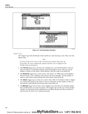
2638A Users Manual Figure 4-3. Test Setup Menu Example hcn032.eps Trigger Type The Trigger Type tells the Product when and how to start when a set the scan to start when a HI or LO channel alarm is tripped on the Digital I/O port detects a low condition. The user sets the number of times to scan (Scan Count) and the time between the scans (Interval). • The Alarm trigger type sets the scan to...
2638A Users Manual Figure 4-3. Test Setup Menu Example hcn032.eps Trigger Type The Trigger Type tells the Product when and how to start when a set the scan to start when a HI or LO channel alarm is tripped on the Digital I/O port detects a low condition. The user sets the number of times to scan (Scan Count) and the time between the scans (Interval). • The Alarm trigger type sets the scan to...

Product Manual
Page 83
... trigger. 4-10 MyFlukeStore Shop for Fluke products online at: www. .com 1.877.766.5412 Configure the Test Setup. Set all channels to be configured to start the scan. Push or to ON then push . Start the scan as "Power Loss Resume State". 2638A Users Manual Automatic Power Loss Scan Resume In the event that it can be accessed. 1. Once the low...
... trigger. 4-10 MyFlukeStore Shop for Fluke products online at: www. .com 1.877.766.5412 Configure the Test Setup. Set all channels to be configured to start the scan. Push or to ON then push . Start the scan as "Power Loss Resume State". 2638A Users Manual Automatic Power Loss Scan Resume In the event that it can be accessed. 1. Once the low...
Product Manual
Page 102
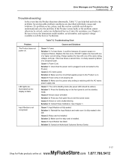
... not installed. 7 Error Messages and Troubleshooting Troubleshooting Troubleshooting In the event that supplies power to the Product is blank. LED lights are described with one of a component part. Table 7-2. Causes and Solutions Cause 1: Fuses. Cause 1: Input Module not fully seated. If the Product seems faulty or the problem cannot otherwise be because of the same rating, voltage, and type. Solution 2: Make sure the circuit that...
... not installed. 7 Error Messages and Troubleshooting Troubleshooting Troubleshooting In the event that supplies power to the Product is blank. LED lights are described with one of a component part. Table 7-2. Causes and Solutions Cause 1: Fuses. Cause 1: Input Module not fully seated. If the Product seems faulty or the problem cannot otherwise be because of the same rating, voltage, and type. Solution 2: Make sure the circuit that...

Product Manual
Page 103
... is started. Troubleshooting Chart (cont.) Causes and Solutions Cause 1: USB drive not installed properly. Solution 4: Replace USB drive. Solution 1: Check the trigger type in less than 30 seconds. 2638A Users Manual Problem Cannot read USB drive. Product does not start a scan. Cause 4: USB drive inoperative or damaged. Solution: Manually push record to scan after the scan is waiting to free up memory. 7-18 MyFlukeStore Shop for Fluke...
... is started. Troubleshooting Chart (cont.) Causes and Solutions Cause 1: USB drive not installed properly. Solution 4: Replace USB drive. Solution 1: Check the trigger type in less than 30 seconds. 2638A Users Manual Problem Cannot read USB drive. Product does not start a scan. Cause 4: USB drive inoperative or damaged. Solution: Manually push record to scan after the scan is waiting to free up memory. 7-18 MyFlukeStore Shop for Fluke...


