Fujitsu MPC3096AT - Desktop 9.7 GB Hard Drive Support and Manuals
Get Help and Manuals for this Fujitsu item
View All Support Options Below
Free Fujitsu MPC3096AT manuals!
Problems with Fujitsu MPC3096AT?
Ask a Question
Free Fujitsu MPC3096AT manuals!
Problems with Fujitsu MPC3096AT?
Ask a Question
Popular Fujitsu MPC3096AT Manual Pages
Product Manual - Page 8

... and performance 1 - 1 1.1.2 Adaptability...1 - 2 1.1.3 Interface...1 - 2 1.2 Device Specifications ...1 - 4 1.2.1 Specifications summary 1 - 4 1.2.2 Model and product number 1 - 5 1.3 Power Requirements...1 - 5 1.4 Environmental Specifications 1 - 8 1.5 Acoustic Noise ...1 - 8 1.6 Shock and Vibration...1 - 9 1.7 Reliability ...1 - 9 1.8 Error Rate ...1 - 10 1.9 Media Defects...1 - 10
CHAPTER...
Product Manual - Page 12

...Mounting frame structure 3 - 4 3.5 Surface temperature measurement points 3 - 5 3.6 Service area ...3 - 6 3.7 Connector locations...3 - 7 3.8 Cable connections...3 - 8 3.9 Power supply connector pins (CN1 3 - 9 3.10 Jumper location ...3 - 9 3.11 Factory default setting ...3 - 10 3.12 Jumper setting of master or slave device 3 - 10 3.13 Jumper setting of Cable Select 3 - 11 3.14 Example (1) of...
Product Manual - Page 24

...repair (MTTR)
The mean time between failures (MTBF) is less than 48°C. This does not include failures occurring during the first three months after installation. Disk drive defects do not include failures caused by a specialist maintenance staff member.
(3) Service... repair, readjustment, or replacement.
1.6 Shock and Vibration Table 1.6 lists the shock and vibration specification....
Product Manual - Page 37

... areas) during and after installation.
- Mounting screw hole
[P side] - Ensure that the disk drive is not affected by external magnetic fields.
3 - 6
C141-E055-01EN Mounting screw hole
Figure 3.6 Service area
(6) External magnetic fields
Avoid mounting the disk drive near strong magnetic sources such as loud speakers. Cable connection - Mode setting switches
[R side] - Mounting...
Product Manual - Page 39
...specifications
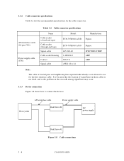
Name Cable socket (closed-end type) Cable socket (through-end type) Signal cable Cable socket housing Contact Signal cable
Model
Manufacturer
FCN-707B040-AU/B Fujitsu
FCN-707B040-AU/O Fujitsu... Cable connections
3 - 8
C141-E055-01EN 3.3.2 Cable connector specifications Table 3.2 lists the recommended specifications for the host interface cable. It is because that the location ...
Product Manual - Page 43

...heads 16 16 16 16 16 16
No. of cylinders reported by the IDENTIFY DEVICE command is selected. (a) Default mode
2 4 6
2 4 6
2 4 6
1 3 5 Master Device
Model MPC3032AT MPC3043AT MPC3064AT MPC3084AT MPC3096AT MPC3102AT
1 3 5 Slave Device
1 3 5 Cable Select
No. (3) Special setting 1 (SP1) The number of sectors 63 63 63 63 63 63
(b) Special mode 2 4 6
2 4 6
2 4 6
1 3 5 Master Device...
Product Manual - Page 56

...the data transfer rate is set so that includes the time base generator circuit to set the data transfer rate. ... Table 4.2 Write clock frequency and transfer rate of each zone
MPC3032AT/MPC3043AT/MPC3064AT/MPC3084AT/MPC3096AT
Zone
0
1
2
3
4
5
6
7
Cylinder
0
981 1961 2961 3896 ....60 12.58
The MPU transfers the data transfer rate setup data (SDATA/SCLK) to the RDC that the recording...
Product Manual - Page 69

.../O registers.
5 - 6
C141-E055-01EN The IDENTIFY DEVICE information indicates whether the device supports the LBA mode.
LBA = [((Cylinder No.) × (Number of head) + ...changed. 5.2 Logical Interface
The device can be selected by the coded signals, CS0-, CS1-, and DA0 to HS0 bits of LBA0... system changes the assignment of the CHS mode by setting bit 6 in the ascending order with the start ...
Product Manual - Page 77

...DMA SET FEATURES SET MULTIPLE MODE EXECUTE DEVICE DIAGNOSTIC FORMAT TRACK READ LONG WRITE LONG READ BUFFER WRITE BUFFER IDLE
IDLE IMMEDIATE
STANDBY
Command code (...1 0
0 0
1 1
NNNND
1 1
0 1
0 1
1 0
0 0
1 0
1 1
0 0
NYNND
5 - 14
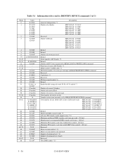
C141-E055-01EN 5.3.1 Command code and parameters
Table 5.3 lists the supported commands, command code and the registers that needed parameters are written.
Product Manual - Page 93
...Firmware revision (ASCII code) *3
Model number (ASCII code) *4
Maximum number of sectors per interrupt on READ/WRITE MULTIPLE command
Reserved
Capabilities *5
Reserved
PIO data transfer mode *6
Retired
Enable/disable setting... : 120 [ns]
Reserved
Major version number *11
Minor version number (not reported)
Support of command sets *12
Support of 3)
Word 0 1
2 3
4 5 6 7-9 10-19 20-21 22...
Product Manual - Page 94

... 23-26: Firmware revision; ASCII code (40 characters, Left-justified), remainder filled with blank code (X'20') One of word 54-58 1=Enable
C141-E055-03EN
5 - 31 MPC3032AT, MPC3043AT, MPC3064AT, MPC3084AT, MPC3096AT, MPC3102AT
*5 Word 49: Capabilities
Bit 15-14: Reserved
Bit 13: Standby timer value 0 = vendor specific
Bit 12: Reserved
Bit 11: IORDY support 1=Supported
Bit 10: IORDY...
Product Manual - Page 101

... sets the BSY bit. The READ LONG command supports ...error correction is not performed for keep the compatibility with the WRITE LONG command. Number of ECC bytes to be transferred is used for checking ECC function by the SET...01H Diagnostic code
*1 This register indicates X'00' in the requested sector and the ECC bytes to the host system. At command issuance (I/O registers setting contents)
...
Product Manual - Page 106

...CH) 1F4H(CL) 1F3H(SN) 1F2H(SC) 1F1H(ER)
xx xx xx xx Error information
C141-E055-01EN
5 - 43 This command does not support the automatic power-down function. At command completion (I /O registers contents to be ...) 1F2H(SC) 1F1H(ER)
xx xx xx xx Error information
(23) IDLE IMMEDIATE (X'95' or X'E1')
Upon receipt of this command, the device sets the BSY bit of the Status register, and enters ...
Product Manual - Page 107

...is stopped. This command does not support the automatic power-down sequence is disabled. (24) STANDBY (X'96' or X'E2')
Upon receipt of this command, the device sets the BSY bit of the Status register...(SN) 1F2H(SC) 1F1H(ER)
xx xx xx xx Error information
(25) STANDBY IMMEDIATE (X'94' or X'E0')
Upon receipt of this command, the device sets the BSY bit of the Sector Count register is other than...
Product Manual - Page 126

... signal lines are used for propagation delay, cable settling, and setup time, the sender shall generate a STROBE edge to allow for...DMA Mode 2). 5.5 Ultra DMA feature set
5.5.1 Overview
Ultra DMA is capable of supporting. Both edges of STROBE are redefined to the data sent...mode of the command, the device shall report the first error that occurred. At the end of an Ultra DMA burst...
Fujitsu MPC3096AT Reviews
We have not received any reviews for Fujitsu yet.