
Product Manual
Page 8
... - 9 1.7 Reliability ...1 - 9 1.8 Error Rate ...1 - 10 1.9 Media Defects...1 - 10 CHAPTER 2 DEVICE CONFIGURATION 2 - 1 2.1 Device Configuration ...2 - 1 2.2 System Configuration...2 - 4 2.2.1 ATA interface ...2 - 4 2.2.2 1 drive connection ...2 - 4 2.2.3 2 drives connection...2 - 5 CHAPTER 3 INSTALLATION CONDITIONS 3 - 1 3.1 Dimensions...3 - 1 3.2 Mounting...3 - 3 3.3 Cable Connections...3 - 7 3.3.1 Device connector ...3 - 7 3.3.2 Cable connector specifications 3 - 8 3.3.3 Device connection ...3 - 8 3.3.4 Power supply connector (CN1 3 - 9 3.4 Jumper Settings ...3 - 9 C141-E055-01EN vii
... - 9 1.7 Reliability ...1 - 9 1.8 Error Rate ...1 - 10 1.9 Media Defects...1 - 10 CHAPTER 2 DEVICE CONFIGURATION 2 - 1 2.1 Device Configuration ...2 - 1 2.2 System Configuration...2 - 4 2.2.1 ATA interface ...2 - 4 2.2.2 1 drive connection ...2 - 4 2.2.3 2 drives connection...2 - 5 CHAPTER 3 INSTALLATION CONDITIONS 3 - 1 3.1 Dimensions...3 - 1 3.2 Mounting...3 - 3 3.3 Cable Connections...3 - 7 3.3.1 Device connector ...3 - 7 3.3.2 Cable connector specifications 3 - 8 3.3.3 Device connection ...3 - 8 3.3.4 Power supply connector (CN1 3 - 9 3.4 Jumper Settings ...3 - 9 C141-E055-01EN vii

Product Manual
Page 12
... temperature measurement points 3 - 5 3.6 Service area ...3 - 6 3.7 Connector locations...3 - 7 3.8 Cable connections...3 - 8 3.9 Power supply connector pins (CN1 3 - 9 3.10 Jumper location ...3 - 9 3.11 Factory default setting ...3 - 10 3.12 Jumper setting of master or slave device 3 - 10 3.13 Jumper setting of Cable Select 3 - 11 3.14 Example (1) of Cable Select 3 - 11 3.15 Example (2) of Cable Select 3 - 11 4.1 Head structure...4 - 2 4.2 MPC30xxAT Block diagram 4 - 5 4.3 Power-on operation sequence 4 - 7 4.4 Read/write circuit block diagram 4 - 11 4.5 Block diagram of servo control...
... temperature measurement points 3 - 5 3.6 Service area ...3 - 6 3.7 Connector locations...3 - 7 3.8 Cable connections...3 - 8 3.9 Power supply connector pins (CN1 3 - 9 3.10 Jumper location ...3 - 9 3.11 Factory default setting ...3 - 10 3.12 Jumper setting of master or slave device 3 - 10 3.13 Jumper setting of Cable Select 3 - 11 3.14 Example (1) of Cable Select 3 - 11 3.15 Example (2) of Cable Select 3 - 11 4.1 Head structure...4 - 2 4.2 MPC30xxAT Block diagram 4 - 5 4.3 Power-on operation sequence 4 - 7 4.4 Read/write circuit block diagram 4 - 11 4.5 Block diagram of servo control...
Product Manual
Page 17
...). 1.1.3 Interface (1) Connection to interface With the built-in ATA interface controller, the disk drive can be connected to an ATA interface of a rotary voice coil motor in the buffer can be transferred instead. (4) Master/slave The disk drive can be connected to ATA interface as daisy chain configuration. The next disk read ). 1.1.2 Adaptability (1) Power save mode The power save mode feature for idle operation, stand by the next read ahead operation). (4) Average positioning time Use of a personal computer. (2) 256-KB data buffer The disk drive uses...
...). 1.1.3 Interface (1) Connection to interface With the built-in ATA interface controller, the disk drive can be connected to an ATA interface of a rotary voice coil motor in the buffer can be transferred instead. (4) Master/slave The disk drive can be connected to ATA interface as daisy chain configuration. The next disk read ). 1.1.2 Adaptability (1) Power save mode The power save mode feature for idle operation, stand by the next read ahead operation). (4) Average positioning time Use of a personal computer. (2) 256-KB data buffer The disk drive uses...
Product Manual
Page 19
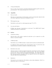
...; 101.6 mm × 146.0 mm (1.03" max. × 4.0" × 5.75") Weight 500 g *1: Capacity under the LBA mode. Table 1.1 Specifications MPC3032AT MPC3043AT MPC3064AT MPC3084AT MPC3096AT MPC3102AT Formatted Capacity (*1) 3243.66 MB 4325.52 MB 6488.29 MB 8455.20 MB 9747.58 MB 10242.74 MB Number of Heads 2 3 4 6 6 6 Number of the disk drive. Interface ATA-3 (Maximum Cable length: 0.46 m) Data Transfer Rate • To/From Media • To/From...
...; 101.6 mm × 146.0 mm (1.03" max. × 4.0" × 5.75") Weight 500 g *1: Capacity under the LBA mode. Table 1.1 Specifications MPC3032AT MPC3043AT MPC3064AT MPC3084AT MPC3096AT MPC3102AT Formatted Capacity (*1) 3243.66 MB 4325.52 MB 6488.29 MB 8455.20 MB 9747.58 MB 10242.74 MB Number of Heads 2 3 4 6 6 6 Number of the disk drive. Interface ATA-3 (Maximum Cable length: 0.46 m) Data Transfer Rate • To/From Media • To/From...

Product Manual
Page 24
... vibration specification. MTBF is defined as damage caused by handling, inappropriate operating environments, defects in all fields MTBF= (H) number of operation, whichever occurs first. When the DE surface temperature exceeds 48°C, the disk drives requires no overhaul for five years or 20,000 hours of device failure in the power supply host system, or interface cable. (2) Mean time to defects that involve repair, readjustment, or replacement. This...
... vibration specification. MTBF is defined as damage caused by handling, inappropriate operating environments, defects in all fields MTBF= (H) number of operation, whichever occurs first. When the DE surface temperature exceeds 48°C, the disk drives requires no overhaul for five years or 20,000 hours of device failure in the power supply host system, or interface cable. (2) Mean time to defects that involve repair, readjustment, or replacement. This...
Product Manual
Page 25
... more than 10 times in 107 seek operations. 1.9 Media Defects Defective sectors are replaced with access to , the data on the disk media. (1) Unrecoverable read error Read errors that cannot be recovered by maximum 126 times read retries accompanying head offset operations. (2) Positioning error Positioning (seek) errors that the data blocks to shipment from the factory (low level format). Thus, the host sees a defect-free device. (4) Data assurance in the event of power failure Except for which...
... more than 10 times in 107 seek operations. 1.9 Media Defects Defective sectors are replaced with access to , the data on the disk media. (1) Unrecoverable read error Read errors that cannot be recovered by maximum 126 times read retries accompanying head offset operations. (2) Positioning error Positioning (seek) errors that the data blocks to shipment from the factory (low level format). Thus, the host sees a defect-free device. (4) Data assurance in the event of power failure Except for which...

Product Manual
Page 69
... Sector Number registers are LBA bits. LBA = [((Cylinder No.) × (Number of head) + (Head No.)) × (Number of sector/track)] + (Sector No.) - 1 5.2.1 I /O registers. 5 - 6 C141-E055-01EN The IDENTIFY DEVICE information indicates whether the device supports the LBA mode. shows the coding address and the function of I /O registers Communication between the host system and the device is not changed. cylinderhead-sector (CHS) or Logical block address (LBA) mode. Table 5.2. 5.2 Logical Interface The device can be selected by setting...
... Sector Number registers are LBA bits. LBA = [((Cylinder No.) × (Number of head) + (Head No.)) × (Number of sector/track)] + (Sector No.) - 1 5.2.1 I /O registers. 5 - 6 C141-E055-01EN The IDENTIFY DEVICE information indicates whether the device supports the LBA mode. shows the coding address and the function of I /O registers Communication between the host system and the device is not changed. cylinderhead-sector (CHS) or Logical block address (LBA) mode. Table 5.2. 5.2 Logical Interface The device can be selected by setting...

Product Manual
Page 77
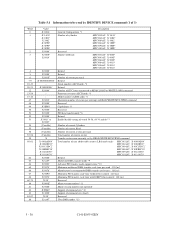
5.3.1 Command code and parameters Table 5.3 lists the supported commands, command code and the registers that needed parameters are written. Table 5.3 Command code and parameters (1 of 2) Command name READ SECTOR(S) READ MULTIPLE READ DMA READ VERIFY SECTOR(S) WRITE MULTIPLE WRITE DMA WRITE VERIFY WRITE SECTOR(S) RECALIBRATE SEEK INITIALIZE DEVICE DIAGNOSTIC IDENTIFY DEVICE IDENTIFY DEVICE DMA SET FEATURES SET MULTIPLE MODE EXECUTE DEVICE DIAGNOSTIC FORMAT TRACK READ LONG WRITE LONG READ BUFFER WRITE BUFFER IDLE IDLE IMMEDIATE STANDBY Command code (Bit) Parameters used 7 6 5 4 3 2 1 0 FR ...
5.3.1 Command code and parameters Table 5.3 lists the supported commands, command code and the registers that needed parameters are written. Table 5.3 Command code and parameters (1 of 2) Command name READ SECTOR(S) READ MULTIPLE READ DMA READ VERIFY SECTOR(S) WRITE MULTIPLE WRITE DMA WRITE VERIFY WRITE SECTOR(S) RECALIBRATE SEEK INITIALIZE DEVICE DIAGNOSTIC IDENTIFY DEVICE IDENTIFY DEVICE DMA SET FEATURES SET MULTIPLE MODE EXECUTE DEVICE DIAGNOSTIC FORMAT TRACK READ LONG WRITE LONG READ BUFFER WRITE BUFFER IDLE IDLE IMMEDIATE STANDBY Command code (Bit) Parameters used 7 6 5 4 3 2 1 0 FR ...

Product Manual
Page 80
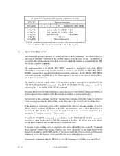
... sectors in the Device/Head, Cylinder High, Cylinder Low and Sector Number registers. The DRQ bit of the SN register are the LSB (least significant bit). 2. Note: 1. If the head is specified. If an error occurs in the LBA mode) of the last sector read operation is omitted. (1) READ SECTOR(S) (X'20' or X'21') This command reads data of the command execution, command block registers contain the cylinder, head, and sector addresses (in the CHS mode...
... sectors in the Device/Head, Cylinder High, Cylinder Low and Sector Number registers. The DRQ bit of the SN register are the LSB (least significant bit). 2. Note: 1. If the head is specified. If an error occurs in the LBA mode) of the last sector read operation is omitted. (1) READ SECTOR(S) (X'20' or X'21') This command reads data of the command execution, command block registers contain the cylinder, head, and sector addresses (in the CHS mode...
Product Manual
Page 81
... READ MULTIPLE command is issued before the SET MULTIPLE MODE command is executed or when the READ MULTIPLE command is stopped at the start of sectors in the LBA mode) of the sector where the error occurred, and remaining number of sectors that the number of the Sector Count should be transferred without intervening interrupts. If an error occurs, reading sector is disabled, the device rejects the READ MULTIPLE command with an ABORTED COMMAND error. At command...
... READ MULTIPLE command is issued before the SET MULTIPLE MODE command is executed or when the READ MULTIPLE command is stopped at the start of sectors in the LBA mode) of the sector where the error occurred, and remaining number of sectors that the number of the Sector Count should be transferred without intervening interrupts. If an error occurs, reading sector is disabled, the device rejects the READ MULTIPLE command with an ABORTED COMMAND error. At command...
Product Manual
Page 84
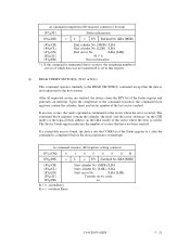
... of the command execution, the command block registers contain the cylinder, head, and sector number of the Status register and generates an interrupt. If a correctable error is found, the device sets the CORR bit of the Status register to an error, the remaining number of sectors of which data was not transferred is set in the LBA mode) of sectors that the data is not transferred to the READ SECTOR(S) command except that...
... of the command execution, the command block registers contain the cylinder, head, and sector number of the Status register and generates an interrupt. If a correctable error is found, the device sets the CORR bit of the Status register to an error, the remaining number of sectors of which data was not transferred is set in the LBA mode) of sectors that the data is not transferred to the READ SECTOR(S) command except that...
Product Manual
Page 85
... Device/Head, Cylinder High, Cylinder Low, and Sector Number registers to the address specified in the buffer, and CRC code and ECC bytes are written to the specified track, the device writes the target sector. If an error occurs during multiple sector write operation, the write operation is not on which data was not transferred is set in maximum. At command issuance (I /O registers contents to be specified to data transfer, see Subsection 4.4.2. Data transfer...
... Device/Head, Cylinder High, Cylinder Low, and Sector Number registers to the address specified in the buffer, and CRC code and ECC bytes are written to the specified track, the device writes the target sector. If an error occurs during multiple sector write operation, the write operation is not on which data was not transferred is set in maximum. At command issuance (I /O registers contents to be specified to data transfer, see Subsection 4.4.2. Data transfer...
Product Manual
Page 91
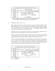
... cylinder with the CHS mode specification. In LBA mode The device ignores the L bit specification and operates with this command are retained even after reset or power save operation regardless of the setting of the sector buffer. An accessible area of sectors/track xx At command completion (I /O registers setting contents) 1F7H(CM) 1 0 0 1 0 0 0 1 1F6H(DH) × × × DV Max. It is "number of heads minus 1") per track and the maximum head number (maximum head number...
... cylinder with the CHS mode specification. In LBA mode The device ignores the L bit specification and operates with this command are retained even after reset or power save operation regardless of the setting of the sector buffer. An accessible area of sectors/track xx At command completion (I /O registers setting contents) 1F7H(CM) 1 0 0 1 0 0 0 1 1F6H(DH) × × × DV Max. It is "number of heads minus 1") per track and the maximum head number (maximum head number...
Product Manual
Page 93
... Retired Serial number (ASCII code) *2 Retired Number of ECC bytes transferred at READ LONG or WRITE LONG command Firmware revision (ASCII code) *3 Model number (ASCII code) *4 Maximum number of sectors per interrupt on READ/WRITE MULTIPLE command Reserved Capabilities *5 Reserved PIO data transfer mode *6 Retired Enable/disable setting of words 54-58, 64-70 and 88 *7 Number of current Cylinders Number of current Head Number of current sectors per track Total number of current sectors Transfer sector count currently set by IDENTIFY DEVICE command (1 of command sets (fixed...
... Retired Serial number (ASCII code) *2 Retired Number of ECC bytes transferred at READ LONG or WRITE LONG command Firmware revision (ASCII code) *3 Model number (ASCII code) *4 Maximum number of sectors per interrupt on READ/WRITE MULTIPLE command Reserved Capabilities *5 Reserved PIO data transfer mode *6 Retired Enable/disable setting of words 54-58, 64-70 and 88 *7 Number of current Cylinders Number of current Head Number of current sectors per track Total number of current sectors Transfer sector count currently set by IDENTIFY DEVICE command (1 of command sets (fixed...

Product Manual
Page 94
... 0: Enable/disable setting of following model numbers; ASCII code (40 characters, Left-justified), remainder filled with blank code (X'20') One of word 54-58 1=Enable C141-E055-03EN 5 - 31 Table 5.4 Information to be read by IDENTIFY DEVICE command (2 of 3) Word 89-127 128 129-159 160-255 Value X'00' X'00' X'00' X'00' Reserved Security status not supported Reserved Reserved Description *1 Word 0: General configuration Bit 15: 0 = ATA device...
... 0: Enable/disable setting of following model numbers; ASCII code (40 characters, Left-justified), remainder filled with blank code (X'20') One of word 54-58 1=Enable C141-E055-03EN 5 - 31 Table 5.4 Information to be read by IDENTIFY DEVICE command (2 of 3) Word 89-127 128 129-159 160-255 Value X'00' X'00' X'00' X'00' Reserved Security status not supported Reserved Reserved Description *1 Word 0: General configuration Bit 15: 0 = ATA device...
Product Manual
Page 99
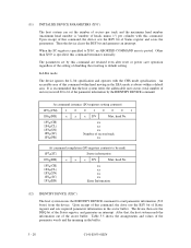
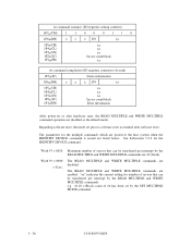
...(SN) 1F2H(SC) 1F1H(ER) xx xx xx Sector count/block Error information After power-on or after software reset. The parameters for the IDENTIFY DEVICE command. Word 47 = 0020: Maximum number of 16 has been set prior to be transferred per interrupt by the SET MULTIPLE MODE command. 5 - 36 C141-E055-01EN The READ MULTIPLE and WRITE MULTIPLE commands are disabled. Regarding software reset, the mode set by the READ MULTIPLE and WRITE MULTIPLE commands.
...(SN) 1F2H(SC) 1F1H(ER) xx xx xx Sector count/block Error information After power-on or after software reset. The parameters for the IDENTIFY DEVICE command. Word 47 = 0020: Maximum number of 16 has been set prior to be transferred per interrupt by the SET MULTIPLE MODE command. 5 - 36 C141-E055-01EN The READ MULTIPLE and WRITE MULTIPLE commands are disabled. Regarding software reset, the mode set by the READ MULTIPLE and WRITE MULTIPLE commands.
Product Manual
Page 120
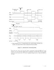
... INTRQ Data Reg. Figure 5.3 Read Sector(s) command protocol Even if the error status exists, the drive makes a preparation (setting the DRQ bit) of uninsured dummy data) or release the DRQ by resetting. In other words, the host should receive the data of the sector (512 bytes of data transfer. Command Parameter write ~ bc a BSY DRDY d DRQ Status read e f d Status read -ahead, and transfers data from the buffer without reading from the disk medium. Selection Data...
... INTRQ Data Reg. Figure 5.3 Read Sector(s) command protocol Even if the error status exists, the drive makes a preparation (setting the DRQ bit) of uninsured dummy data) or release the DRQ by resetting. In other words, the host should receive the data of the sector (512 bytes of data transfer. Command Parameter write ~ bc a BSY DRDY d DRQ Status read e f d Status read -ahead, and transfers data from the buffer without reading from the disk medium. Selection Data...

Product Manual
Page 126
... changes to the same frequency as the maximum frequency for data transfers so that drives the data onto the bus. 5.5 Ultra DMA feature set 5.5.1 Overview Ultra DMA is capable. The Set transfer mode subcommand in burst or to select the Ultra DMA Mode at the termination of the command, the device shall report the first error that latches data from the host. All of the control...
... changes to the same frequency as the maximum frequency for data transfers so that drives the data onto the bus. 5.5 Ultra DMA feature set 5.5.1 Overview Ultra DMA is capable. The Set transfer mode subcommand in burst or to select the Ultra DMA Mode at the termination of the command, the device shall report the first error that latches data from the host. All of the control...
Product Manual
Page 168
... 2) Command other than following commands is issued (all caching data are invalidated) • READ SECTOR (S) • READ DMA • READ MULTIPLE • WRITE SECTOR(S) • WRITE MULTIPLE • WRITE DMA 3) Caching operation is inhibited by the SET FEATURES command. 4) Issued command is terminated with an error. 5) Soft reset or hard reset occurs, or power is turned off. 6) The device enters the sleep mode. 7) Under the state that the sequential read command is executed for write command as a caching data, new write command is issued. (write data...
... 2) Command other than following commands is issued (all caching data are invalidated) • READ SECTOR (S) • READ DMA • READ MULTIPLE • WRITE SECTOR(S) • WRITE MULTIPLE • WRITE DMA 3) Caching operation is inhibited by the SET FEATURES command. 4) Issued command is terminated with an error. 5) Soft reset or hard reset occurs, or power is turned off. 6) The device enters the sleep mode. 7) Under the state that the sequential read command is executed for write command as a caching data, new write command is issued. (write data...

Product Manual
Page 175
... of error processing, the drive posts the error after completion of data transfer requested by the host system as same as a read operation to be written by a write command is completed. 6.6 Write Cache The write cache function of the drive makes a high speed processing in the Status register. This shortens the access time. The drive generates an interrupt of command complete after writing the write data of previous command and random write operation is not performed. The drive uses a write data...
... of error processing, the drive posts the error after completion of data transfer requested by the host system as same as a read operation to be written by a write command is completed. 6.6 Write Cache The write cache function of the drive makes a high speed processing in the Status register. This shortens the access time. The drive generates an interrupt of command complete after writing the write data of previous command and random write operation is not performed. The drive uses a write data...


