
User Manual
Page 2
... in working order. 2. REMOVE ADJUSTING KEYS AND WRENCHES. Form habit of contents Safety 2 Specifications 6 Setup 6 Operation 9 Maintenance 12 Parts Lists and Diagrams 14 Warranty 16 SAFETy SETUp OpERATION WARNING SyMBOLS AND DEFINITIONS This is used to alert you to potential personal injury hazards. Cluttered areas and benches invite accidents. 4. KEEP CHILDREN AWAY. MAKE WORKSHOP KID PROOF with padlocks, master switches, or by removing starter keys. 7. DON'T USE IN DANGEROUS ENVIRONMENT. Item 38144 MAINTENANcE Indicates...
... in working order. 2. REMOVE ADJUSTING KEYS AND WRENCHES. Form habit of contents Safety 2 Specifications 6 Setup 6 Operation 9 Maintenance 12 Parts Lists and Diagrams 14 Warranty 16 SAFETy SETUp OpERATION WARNING SyMBOLS AND DEFINITIONS This is used to alert you to potential personal injury hazards. Cluttered areas and benches invite accidents. 4. KEEP CHILDREN AWAY. MAKE WORKSHOP KID PROOF with padlocks, master switches, or by removing starter keys. 7. DON'T USE IN DANGEROUS ENVIRONMENT. Item 38144 MAINTENANcE Indicates...

User Manual
Page 3
... 14 12 Do not use of injury to operate tool. 13. Make sure switch is in . 17. DIRECTION OF FEED. SECURE WORK. Follow instructions for recommended accessories. Serious injury could occur if the tool is tipped or if the cutting tool is recommended. CHECK DAMAGED PARTS. Don't leave tool until it frees both hands to persons. 18. NEVER STAND ON TOOL. OpERATION MAINTENANcE Item 38144 For technical questions, please call...
... 14 12 Do not use of injury to operate tool. 13. Make sure switch is in . 17. DIRECTION OF FEED. SECURE WORK. Follow instructions for recommended accessories. Serious injury could occur if the tool is tipped or if the cutting tool is recommended. CHECK DAMAGED PARTS. Don't leave tool until it frees both hands to persons. 18. NEVER STAND ON TOOL. OpERATION MAINTENANcE Item 38144 For technical questions, please call...
User Manual
Page 4
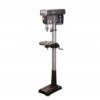
... included chuck key or an identical replacement key. 6. Check with Three prong plugs 1. This tool is intended for up to 125 V~ and up to prevent rotation. 4. Drill press Safety Warnings For your Own Safety Read Instruction Manual Before Operating Drill press 1. Wear eye protection. 2. Grounding pin 125 V~ 3-prong plug and Outlet (for use of the electric cord or plug is properly installed and grounded in accordance with all local codes...
... included chuck key or an identical replacement key. 6. Check with Three prong plugs 1. This tool is intended for up to 125 V~ and up to prevent rotation. 4. Drill press Safety Warnings For your Own Safety Read Instruction Manual Before Operating Drill press 1. Wear eye protection. 2. Grounding pin 125 V~ 3-prong plug and Outlet (for use of the electric cord or plug is properly installed and grounded in accordance with all local codes...
User Manual
Page 5
... particles. (California Health & Safety Code § 25249.5, et seq.) 17. Industrial applications must be supplied by power sanding, sawing, grinding, drilling, and other reproductive harm. These carry important safety information. It must follow OSHA guidelines. 13. Do not use . Avoid unintentional starting. Vibration Safety This tool vibrates during use . Do not smoke during use a power tool while you do the work before use . OpERATION MAINTENANcE Item 38144 For technical questions, please...
... particles. (California Health & Safety Code § 25249.5, et seq.) 17. Industrial applications must be supplied by power sanding, sawing, grinding, drilling, and other reproductive harm. These carry important safety information. It must follow OSHA guidelines. 13. Do not use . Avoid unintentional starting. Vibration Safety This tool vibrates during use . Do not smoke during use a power tool while you do the work before use . OpERATION MAINTENANcE Item 38144 For technical questions, please...
User Manual
Page 6
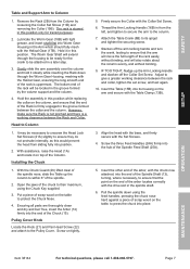
... FROM AccIDENTAL OpERATION: Turn the power Switch of the tool off and unplug the tool from its electrical outlet before set up or use on the Column Support (4B) using the four M10x40mm Hex Head screws (5B). 2. Before assembly, bolt the Base to a flat, level, solid floor location capable of supporting the weight of the drill press and any procedure in the following pages, refer to the Assembly Diagram near the...
... FROM AccIDENTAL OpERATION: Turn the power Switch of the tool off and unplug the tool from its electrical outlet before set up or use on the Column Support (4B) using the four M10x40mm Hex Head screws (5B). 2. Before assembly, bolt the Base to a flat, level, solid floor location capable of supporting the weight of the drill press and any procedure in the following pages, refer to the Assembly Diagram near the...
User Manual
Page 7
... the Table Clamp (13B). 3. Open the jaws of the chuck to give a greater working clearance between the Rack and Collar. Adjust to their maximum, using the feed handles, pressing the chuck nose hard against a piece of scrap wood on top of scrap wood on tightly. 5. Insert the other end of the arbor, with the chuck now attached, into its spigot and tighten the securing screw...
... the Table Clamp (13B). 3. Open the jaws of the chuck to give a greater working clearance between the Rack and Collar. Adjust to their maximum, using the feed handles, pressing the chuck nose hard against a piece of scrap wood on top of scrap wood on tightly. 5. Insert the other end of the arbor, with the chuck now attached, into its spigot and tighten the securing screw...
User Manual
Page 8
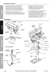
... when the belts deflect by approximately 1/2″ at their centers of the head. Turn the Belt Tension Lever (19A) clockwise to bring the Motor Pulley (11A) close to the Spindle Pulley allowing the belts to spindle/drill speed required. 4. SAFETy Installing the Drive Belts 1. Undo the Belt Tension Locking Knobs (18A) on page 10), and install the Belts in its mounting between the motor and spindle pulleys. Tension is applied to the belts (see Head Assembly diagram).
... when the belts deflect by approximately 1/2″ at their centers of the head. Turn the Belt Tension Lever (19A) clockwise to bring the Motor Pulley (11A) close to the Spindle Pulley allowing the belts to spindle/drill speed required. 4. SAFETy Installing the Drive Belts 1. Undo the Belt Tension Locking Knobs (18A) on page 10), and install the Belts in its mounting between the motor and spindle pulleys. Tension is applied to the belts (see Head Assembly diagram).
User Manual
Page 9
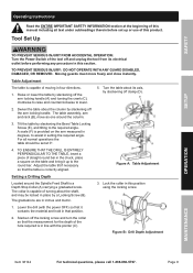
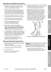
... its electrical outlet before set at the beginning of this manual including all normal operations the table should be locked in place by a Locking Screw (B). Tilt the table by slackening off and unplug the tool from its axis, by slackening off the arm locking handle. The graduations are in degrees, to lower. 5. Figure B: Drill Depth Adjustment OpERATION MAINTENANcE Item 38144 For technical questions, please call 1-888-866-5797. SAFETy SETUp Operating Instructions...
... its electrical outlet before set at the beginning of this manual including all normal operations the table should be locked in place by a Locking Screw (B). Tilt the table by slackening off and unplug the tool from its axis, by slackening off the arm locking handle. The graduations are in degrees, to lower. 5. Figure B: Drill Depth Adjustment OpERATION MAINTENANcE Item 38144 For technical questions, please call 1-888-866-5797. SAFETy SETUp Operating Instructions...
User Manual
Page 10
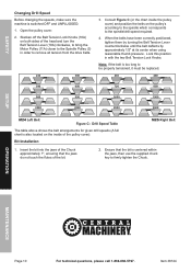
... with the two Belt Tension Lock Knobs. Lock this position in order to the spindle/drill speed required. 4. SETUp OpERATION MAINTENANcE Page 10 For technical questions, please call 1-888-866-5797. Insert the bit into the jaws of the Chuck approximately 1″, ensuring that the bit is centered within the jaws, then use the supplied chuck key to be properly tensioned, it must be replaced. 430 480 590...
... with the two Belt Tension Lock Knobs. Lock this position in order to the spindle/drill speed required. 4. SETUp OpERATION MAINTENANcE Page 10 For technical questions, please call 1-888-866-5797. Insert the bit into the jaws of the Chuck approximately 1″, ensuring that the bit is centered within the jaws, then use the supplied chuck key to be properly tensioned, it must be replaced. 430 480 590...
User Manual
Page 11
... its power supply after use a drill press vise. Severe personal injury may be drilled. Plug the Power Cord into the workpiece. WARNING! If the drill bit grabs and spins the workpiece, do not attempt to reach the work area with your hands. Route the power cord along a safe route to stop turning before dislodging the workpiece. 5. FOR FLAT WORK, lay the piece on . 4. SAFETy SETUp Workpiece and Work Area Set Up...
... its power supply after use a drill press vise. Severe personal injury may be drilled. Plug the Power Cord into the workpiece. WARNING! If the drill bit grabs and spins the workpiece, do not attempt to reach the work area with your hands. Route the power cord along a safe route to stop turning before dislodging the workpiece. 5. FOR FLAT WORK, lay the piece on . 4. SAFETy SETUp Workpiece and Work Area Set Up...
User Manual
Page 12
... 38144 SAFETy Maintenance and Servicing procedures not specifically explained in this power tool is damaged, it must be replaced only by a qualified technician. If the supply cord of moving parts, • cracked or broken parts, • damaged electrical wiring, and • any procedure in this section. Replace belt if damaged, following the instructions under Changing Drill Speed on page 10. TO pREVENT SERIOUS INJURy FROM TOOL FAILURE: Do not use . SETUp OpERATION MAINTENANcE Page...
... 38144 SAFETy Maintenance and Servicing procedures not specifically explained in this power tool is damaged, it must be replaced only by a qualified technician. If the supply cord of moving parts, • cracked or broken parts, • damaged electrical wiring, and • any procedure in this section. Replace belt if damaged, following the instructions under Changing Drill Speed on page 10. TO pREVENT SERIOUS INJURy FROM TOOL FAILURE: Do not use . SETUp OpERATION MAINTENANcE Page...
User Manual
Page 13
... service tool. 2. Eliminate use one with the proper diameter for its length and load. Page 13 Tool's thermal reset breaker tripped (if equipped). 3. Performance decreases over time. Allow machine to cool. Have qualified technician replace brushes. 1. pLEASE READ THE FOLLOWING cAREFULLy THE MANUFACTURER AND/OR DISTRIBUTOR HAS PROVIDED THE PARTS LIST AND ASSEMBLY DIAGRAM IN THIS MANUAL AS A REFERENCE TOOL ONLY. Replace as needed , use of motor using compressed air. 4. Turn off tool...
... service tool. 2. Eliminate use one with the proper diameter for its length and load. Page 13 Tool's thermal reset breaker tripped (if equipped). 3. Performance decreases over time. Allow machine to cool. Have qualified technician replace brushes. 1. pLEASE READ THE FOLLOWING cAREFULLy THE MANUFACTURER AND/OR DISTRIBUTOR HAS PROVIDED THE PARTS LIST AND ASSEMBLY DIAGRAM IN THIS MANUAL AS A REFERENCE TOOL ONLY. Replace as needed , use of motor using compressed air. 4. Turn off tool...
User Manual
Page 14
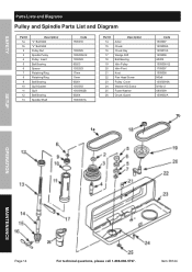
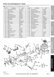
... 13030002B 60204 13003001A Part # 14 15 16 17 18 19 20 21 22 23 24 25 26 Description Arbor Chuck Chuck Key Wedge Drift Ball Bearing Idler Pulley Idler Pivot Knot Pan Head Screw Pulley Cover Washer HD Screw Foam Washer Chuck Guard 1a Code 1503007 1503009A 1503010A 1503008 60202 1505006-02 1705007 1505008 M5x8 13050000A M16x12 0805009 1508002A 1b SETUp OpERATION MAINTENANcE Page 14 For...
... 13030002B 60204 13003001A Part # 14 15 16 17 18 19 20 21 22 23 24 25 26 Description Arbor Chuck Chuck Key Wedge Drift Ball Bearing Idler Pulley Idler Pivot Knot Pan Head Screw Pulley Cover Washer HD Screw Foam Washer Chuck Guard 1a Code 1503007 1503009A 1503010A 1503008 60202 1505006-02 1705007 1505008 M5x8 13050000A M16x12 0805009 1508002A 1b SETUp OpERATION MAINTENANcE Page 14 For...
User Manual
Page 15
... 39A 40A 41A 42A 43A 44A 45A 46A Description Feed Handle Spindle Feed Shaft Collar Depth Stop, w/scale Stop Pin Connector Wire Lock Washer Ext. 5mm Pan Head Screw M5 Switch Switch Plate Cover Pan Head Screw Pan Head Screw M5 Switch Box Screw-Special Set M8 Hex. Nut M12 Quill Spring Cap Quill Spring - - SAFETy parts List and Diagram A - Head Note: All part numbers shown in this diagram have an "A" suffix Part # 1A 2A 3A 4A 5A 6A 7A 8A 9A 10A...
... 39A 40A 41A 42A 43A 44A 45A 46A Description Feed Handle Spindle Feed Shaft Collar Depth Stop, w/scale Stop Pin Connector Wire Lock Washer Ext. 5mm Pan Head Screw M5 Switch Switch Plate Cover Pan Head Screw Pan Head Screw M5 Switch Box Screw-Special Set M8 Hex. Nut M12 Quill Spring Cap Quill Spring - - SAFETy parts List and Diagram A - Head Note: All part numbers shown in this diagram have an "A" suffix Part # 1A 2A 3A 4A 5A 6A 7A 8A 9A 10A...
User Manual
Page 16
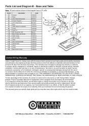
Screw Set M6 Bevel Table Lock Screw Table Clamp Arm w/ scale Table Arm Locking Handle Helical Gear Worm Collar Belt Tension Lever Code 1301003 1301010 M10x12 1301002 M10x40 1301001 1501004 1001009 1501007 M6x10 M16x35 1501013 1301005 1601014 1501012 1501006 1501008 1501011 1502004 Limited 90 Day Warranty Harbor Freight Tools Co. Some states do not allow the exclusion or limitation of incidental or consequential damages, so the above limitation of purchase...
Screw Set M6 Bevel Table Lock Screw Table Clamp Arm w/ scale Table Arm Locking Handle Helical Gear Worm Collar Belt Tension Lever Code 1301003 1301010 M10x12 1301002 M10x40 1301001 1501004 1001009 1501007 M6x10 M16x35 1501013 1301005 1601014 1501012 1501006 1501008 1501011 1502004 Limited 90 Day Warranty Harbor Freight Tools Co. Some states do not allow the exclusion or limitation of incidental or consequential damages, so the above limitation of purchase...


