Maintenance and Service Guide
Page 8
Hard drive cover ...32 Hard drive/SSD drive ...33 mSATA drive ...35 RTC battery ...37 Service cover ...38 Memory module ...39 WWAN module ...41 WLAN module ...43 Keyboard ...45 6 Removal and replacement procedures for Authorized Service ...
Hard drive cover ...32 Hard drive/SSD drive ...33 mSATA drive ...35 RTC battery ...37 Service cover ...38 Memory module ...39 WWAN module ...41 WLAN module ...43 Keyboard ...45 6 Removal and replacement procedures for Authorized Service ...

Maintenance and Service Guide
Page 10
...(purchased separately 97 Using Windows Refresh or Windows Reset 97 Using HP Software Setup ...97 13 Backup and recovery in Windows 10 ...98 Creating recovery media and backups ...98 Creating HP Recovery media (select products only 98 Using Windows tools ...99 ... the computer boot order 102 Removing the HP Recovery partition (select products only 103 14 Specifications ...104 Computer specifications ...104 35.6-cm (14.0-in) display specifications ...105 Hard drive specifications ...106 Solid-state drive specifications ...107 mSATA drive specifications ...108 15 Statement of Volatility ......
...(purchased separately 97 Using Windows Refresh or Windows Reset 97 Using HP Software Setup ...97 13 Backup and recovery in Windows 10 ...98 Creating recovery media and backups ...98 Creating HP Recovery media (select products only 98 Using Windows tools ...99 ... the computer boot order 102 Removing the HP Recovery partition (select products only 103 14 Specifications ...104 Computer specifications ...104 35.6-cm (14.0-in) display specifications ...105 Hard drive specifications ...106 Solid-state drive specifications ...107 mSATA drive specifications ...108 15 Statement of Volatility ......

Maintenance and Service Guide
Page 13
1 Product description Category Product Name Processors Chipset Graphics Panels Memory Flash cache Hard drive Solid-state drive MiniCard SSD Description HP EliteBook Folio 9480m Notebook PC Intel® Core® processors: ● i7-4650U 1.7-GHz (max turbo frequency 3.3-GHz), 4-MB L3 Cache, 15W &#...upgradable memory module slots DDR3L PC3-1600-MHz dual channel support Supports 16384-MB of system RAM in ) SATA hard drives and solid-state drives ● 500-GB, 7200-rpm, self-encrypting drive (SED) ● 500-GB, 7200-rpm Supports the following configurations: ● 16384-MB (8192-MB&#...
1 Product description Category Product Name Processors Chipset Graphics Panels Memory Flash cache Hard drive Solid-state drive MiniCard SSD Description HP EliteBook Folio 9480m Notebook PC Intel® Core® processors: ● i7-4650U 1.7-GHz (max turbo frequency 3.3-GHz), 4-MB L3 Cache, 15W &#...upgradable memory module slots DDR3L PC3-1600-MHz dual channel support Supports 16384-MB of system RAM in ) SATA hard drives and solid-state drives ● 500-GB, 7200-rpm, self-encrypting drive (SED) ● 500-GB, 7200-rpm Supports the following configurations: ● 16384-MB (8192-MB&#...

Maintenance and Service Guide
Page 16
... 64 ● Windows 7 Professional 64- and 32-bit ● Windows 7 Enterprise 64- and 32-bit End user replaceable parts: ● AC adapter ● Battery ● Hard drive ● Solid-state drive ● Keyboard ● Memory module ● mSATA flash cache ● WLAN module ● WWAN module 4 Chapter 1 Product description
... 64 ● Windows 7 Professional 64- and 32-bit ● Windows 7 Enterprise 64- and 32-bit End user replaceable parts: ● AC adapter ● Battery ● Hard drive ● Solid-state drive ● Keyboard ● Memory module ● mSATA flash cache ● WLAN module ● WWAN module 4 Chapter 1 Product description
Maintenance and Service Guide
Page 23
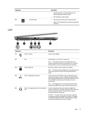
...to cool internal components. Some USB devices require power and require you to cool internal components and prevent overheating. Component (4) Hard drive light Left Description the battery reaches a critical battery level, the battery light begins blinking rapidly. ● Off: The ...device, such as a deterrent, but it may not prevent the computer from being accessed. ● Amber: HP 3D DriveGuard has temporarily parked the hard drive. Component (1) Power connector Description Connects an AC adapter. (2) Vent Enables airflow to act as a keyboard, mouse, ...
...to cool internal components. Some USB devices require power and require you to cool internal components and prevent overheating. Component (4) Hard drive light Left Description the battery reaches a critical battery level, the battery light begins blinking rapidly. ● Off: The ...device, such as a deterrent, but it may not prevent the computer from being accessed. ● Amber: HP 3D DriveGuard has temporarily parked the hard drive. Component (1) Power connector Description Connects an AC adapter. (2) Vent Enables airflow to act as a keyboard, mouse, ...
Maintenance and Service Guide
Page 26
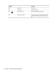
Releases the battery from the battery bay. Supports a wireless subscriber identity module (SIM). The SIM slot is located inside the battery bay. 14 Chapter 2 External component identification Holds the battery. Contains the hard drive. Component (4) (5) (6) (7) Speakers (2) Hard drive bay Battery release latch Battery bay and SIM slot Description Produce sound.
Releases the battery from the battery bay. Supports a wireless subscriber identity module (SIM). The SIM slot is located inside the battery bay. 14 Chapter 2 External component identification Holds the battery. Contains the hard drive. Component (4) (5) (6) (7) Speakers (2) Hard drive bay Battery release latch Battery bay and SIM slot Description Produce sound.
Maintenance and Service Guide
Page 30
...-xxx ● Intel Core i5-4310U processor 769718-xxx ● Intel Core i5-4210U processor 769717-xxx Plastics Kit, includes: 702877-001 SD card insert Hard drive cover Heat sink (includes replacement thermal material): 769708-001 RTC battery 702853-001 Fingerprint reader board (includes cable) 702845-001 Base enclosure 702863-001 Service...
...-xxx ● Intel Core i5-4310U processor 769718-xxx ● Intel Core i5-4210U processor 769717-xxx Plastics Kit, includes: 702877-001 SD card insert Hard drive cover Heat sink (includes replacement thermal material): 769708-001 RTC battery 702853-001 Fingerprint reader board (includes cable) 702845-001 Base enclosure 702863-001 Service...
Maintenance and Service Guide
Page 31
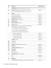
... LTE/EV-DO/HSPA+ Gobi 4G Module 793116-001 HP hs3110 HSPA+ Mobile Broadband Module 822828-001 (18) Solid-state drive (SSD), M.2: 120-GB, M.2 769712-001 32-GB, M.2 769711-001 Hard Drive Hardware Kit (not illustrated, includes hard drive bracket, connector, and screws) 702870-001 (19) Solid-state drive (includes bracket, connector, and screws): 256-GB, SATA...
... LTE/EV-DO/HSPA+ Gobi 4G Module 793116-001 HP hs3110 HSPA+ Mobile Broadband Module 822828-001 (18) Solid-state drive (SSD), M.2: 120-GB, M.2 769712-001 32-GB, M.2 769711-001 Hard Drive Hardware Kit (not illustrated, includes hard drive bracket, connector, and screws) 702870-001 (19) Solid-state drive (includes bracket, connector, and screws): 256-GB, SATA...
Maintenance and Service Guide
Page 33
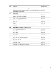
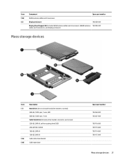
... and transceivers, and display enclosure) Mass storage devices Item Description (1) Hard drive (does not include hard drive bracket or screws): 500-GB, 7200-rpm, 7-mm, SED 500-GB, 7200-rpm, 7-mm Solid-State Drive (includes drive bracket, connector, and screws): 256-GB, SATA III, self-encrypting drive (SED) 240-GB SSD, SATA III 180-GB, SATA III...
... and transceivers, and display enclosure) Mass storage devices Item Description (1) Hard drive (does not include hard drive bracket or screws): 500-GB, 7200-rpm, 7-mm, SED 500-GB, 7200-rpm, 7-mm Solid-State Drive (includes drive bracket, connector, and screws): 256-GB, SATA III, self-encrypting drive (SED) 240-GB SSD, SATA III 180-GB, SATA III...
Maintenance and Service Guide
Page 34
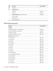
Item (2c) (3) Description Drive connector Solid-state drive, M.2: 120-GB, M.2 32-GB, M.2 Hard Drive Hardware Kit (not illustrated), includes: Hard drive connector Hard drive bracket Hard drive bracket screws Miscellaneous parts Component AC adapter: 45-W HP Smart AC adapter, 7.4 mm, slim (non-PFC) 45-W HP Smart AC adapter, 2 prong (non-PFC) 65-W HP Smart AC adapter 65-W HP Smart AC adapter for use in India...
Item (2c) (3) Description Drive connector Solid-state drive, M.2: 120-GB, M.2 32-GB, M.2 Hard Drive Hardware Kit (not illustrated), includes: Hard drive connector Hard drive bracket Hard drive bracket screws Miscellaneous parts Component AC adapter: 45-W HP Smart AC adapter, 7.4 mm, slim (non-PFC) 45-W HP Smart AC adapter, 2 prong (non-PFC) 65-W HP Smart AC adapter 65-W HP Smart AC adapter for use in India...
Maintenance and Service Guide
Page 37
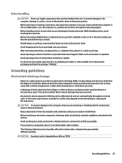
... a while, then degrade in the internal layers, reducing its life expectancy. After removing a hard drive, an optical drive, or a diskette drive, place it in an electrostatic-safe container. If a drive must be affected at least one inch of shock-proof foam. A discharge of static electricity ... all and can be sure that you are removing or installing internal components, observe these precautions: Before removing or inserting a hard drive, shut down through the operating system. Handle electronic components as little as 700 V. The following table shows how humidity affects...
... a while, then degrade in the internal layers, reducing its life expectancy. After removing a hard drive, an optical drive, or a diskette drive, place it in an electrostatic-safe container. If a drive must be affected at least one inch of shock-proof foam. A discharge of static electricity ... all and can be sure that you are removing or installing internal components, observe these precautions: Before removing or inserting a hard drive, shut down through the operating system. Handle electronic components as little as 700 V. The following table shows how humidity affects...
Maintenance and Service Guide
Page 44
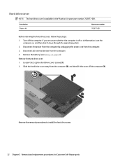
...replacement procedures for Customer Self-Repair parts Remove the battery (see Battery on , and then shut it down through the operating system. 2. Slide the hard drive cover away from the computer (2), and then lift the cover off or in the Plastics kit, spare part number 702877-001. Disconnect the power ...from the computer by unplugging the power cord from the computer. 4. Loosen the 2 captive hard drive cover screws (1). 2. If you are unsure whether the computer is available in Hibernation, turn the computer on page 29). Remove the...
...replacement procedures for Customer Self-Repair parts Remove the battery (see Battery on , and then shut it down through the operating system. 2. Slide the hard drive cover away from the computer (2), and then lift the cover off or in the Plastics kit, spare part number 702877-001. Disconnect the power ...from the computer by unplugging the power cord from the computer. 4. Loosen the 2 captive hard drive cover screws (1). 2. If you are unsure whether the computer is available in Hibernation, turn the computer on page 29). Remove the...
Maintenance and Service Guide
Page 45
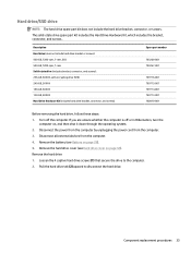
... 703267-001 769716-001 769715-001 769714-001 769713-001 702870-001 Before removing the hard drive, follow these steps: 1. Remove the hard drive: 1. Disconnect all external devices from the computer. 3. The solid-state drive spare part kit includes the Hard Drive Hardware Kit, which includes the bracket, connector, and screws.. Component replacement procedures 33 Loosen the...
... 703267-001 769716-001 769715-001 769714-001 769713-001 702870-001 Before removing the hard drive, follow these steps: 1. Remove the hard drive: 1. Disconnect all external devices from the computer. 3. The solid-state drive spare part kit includes the Hard Drive Hardware Kit, which includes the bracket, connector, and screws.. Component replacement procedures 33 Loosen the...
Maintenance and Service Guide
Page 46
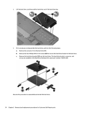
Remove the hard drive bracket (3) from the hard drive (1). b. The hard drive bracket, connector, and screws are available in the Hard Drive Hardware Kit, spare part number 702870-001. 3. If it is necessary to the hard drive. Remove the four Phillips PM3.0×4.0 screws (2) that secure the hard drive bracket to disassemble the hard drive, perform the following steps: a. Reverse this procedure to reassemble and...
Remove the hard drive bracket (3) from the hard drive (1). b. The hard drive bracket, connector, and screws are available in the Hard Drive Hardware Kit, spare part number 702870-001. 3. If it is necessary to the hard drive. Remove the four Phillips PM3.0×4.0 screws (2) that secure the hard drive bracket to disassemble the hard drive, perform the following steps: a. Reverse this procedure to reassemble and...
Maintenance and Service Guide
Page 47
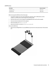
... 35 Disconnect the power from the computer by unplugging the power cord from the computer. 4. Disconnect all external devices from the computer. 3. Remove the mSATA drive: 1. Remove the hard drive cover (see Battery on page 32). If you are unsure whether the computer is off the computer. Remove the battery (see...
... 35 Disconnect the power from the computer by unplugging the power cord from the computer. 4. Disconnect all external devices from the computer. 3. Remove the mSATA drive: 1. Remove the hard drive cover (see Battery on page 32). If you are unsure whether the computer is off the computer. Remove the battery (see...
Maintenance and Service Guide
Page 49
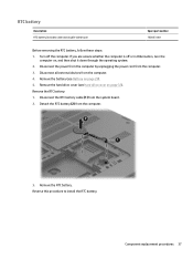
...number 702853-001 Before removing the RTC battery, follow these steps: 1. Remove the RTC battery: 1. Detach the RTC battery (2) from the computer. 3. Remove the hard drive cover (see Battery on page 29). 5. Turn off or in Hibernation, turn the computer on page 32). Disconnect the power from the computer by unplugging.... Reverse this procedure to install the RTC battery. If you are unsure whether the computer is off the computer. Remove the battery (see Hard drive cover on , and then shut it down through the operating system. 2. Component replacement procedures 37
...number 702853-001 Before removing the RTC battery, follow these steps: 1. Remove the RTC battery: 1. Detach the RTC battery (2) from the computer. 3. Remove the hard drive cover (see Battery on page 29). 5. Turn off or in Hibernation, turn the computer on page 32). Disconnect the power from the computer by unplugging.... Reverse this procedure to install the RTC battery. If you are unsure whether the computer is off the computer. Remove the battery (see Hard drive cover on , and then shut it down through the operating system. 2. Component replacement procedures 37
Maintenance and Service Guide
Page 50
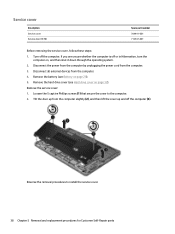
... replacement procedures for Customer Self-Repair parts Reverse the removal procedures to the computer. 2. Turn off the computer (3). Remove the battery (see Hard drive cover on page 32). Remove the hard drive cover (see Battery on , and then shut it down through the operating system. 2. Disconnect all external devices from the computer. 3. Tilt the...
... replacement procedures for Customer Self-Repair parts Reverse the removal procedures to the computer. 2. Turn off the computer (3). Remove the battery (see Hard drive cover on page 32). Remove the hard drive cover (see Battery on , and then shut it down through the operating system. 2. Disconnect all external devices from the computer. 3. Tilt the...
Maintenance and Service Guide
Page 51
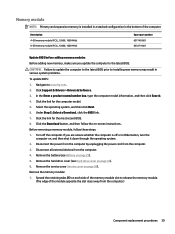
... of the computer. CAUTION: Failure to update the computer to the latest BIOS prior to www.hp.com. 2. Click the link for the most recent BIOS. 8. Remove the battery (see Hard drive cover on page 32). 6. Memory module NOTE: Primary and expansion memory is off the computer....information, and then click Search. 4. Disconnect the power from the computer by unplugging the power cord from the computer. 4. Remove the hard drive cover (see Battery on each side of the module opposite the slot rises away from the computer.) Component replacement procedures 39 Spread the ...
... of the computer. CAUTION: Failure to update the computer to the latest BIOS prior to www.hp.com. 2. Click the link for the most recent BIOS. 8. Remove the battery (see Hard drive cover on page 32). 6. Memory module NOTE: Primary and expansion memory is off the computer....information, and then click Search. 4. Disconnect the power from the computer by unplugging the power cord from the computer. 4. Remove the hard drive cover (see Battery on each side of the module opposite the slot rises away from the computer.) Component replacement procedures 39 Spread the ...
Maintenance and Service Guide
Page 53
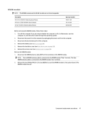
...cables (1) from the computer. 4. Remove the WWAN module: 1. NOTE: The red WWAN antenna cable is off the computer. Remove the battery (see Hard drive cover on , and then shut it down through the operating system. 2. Turn off or in Hibernation, turn the computer on page 32). 6. Disconnect...module are unsure whether the computer is connected to the WWAN module "Main" terminal. Description HP lt4112 LTE/HSPA+ Mobile Broadband Module HP lt4211 LTE/EV-DO/HSPA+ Gobi 4G Module HP hs3110 HSPA+ Mobile Broadband Module Spare part number 740011-001 793116-001 822828-001 Before ...
...cables (1) from the computer. 4. Remove the WWAN module: 1. NOTE: The red WWAN antenna cable is off the computer. Remove the battery (see Hard drive cover on , and then shut it down through the operating system. 2. Turn off or in Hibernation, turn the computer on page 32). 6. Disconnect...module are unsure whether the computer is connected to the WWAN module "Main" terminal. Description HP lt4112 LTE/HSPA+ Mobile Broadband Module HP lt4211 LTE/EV-DO/HSPA+ Gobi 4G Module HP hs3110 HSPA+ Mobile Broadband Module Spare part number 740011-001 793116-001 822828-001 Before ...
Maintenance and Service Guide
Page 55
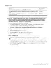
...(see Battery on page 32). 6. Remove the hard drive cover (see Service cover on , and then shut it down through the operating system. 2. WLAN module Description Intel Dual Band Wireless-AC 7260 802.11 AC 2x2 WiFi + BT 4.0 Combo Adapter HP Intel Dual Band Wireless-N 7260AN 802.11 a/b/g/n ...regulates wireless devices in Hibernation, turn the computer on page 38). Turn off or in your country or region. Remove the service cover (see Hard drive cover on page 29). 5. The WLAN antenna cable labeled "2" connects to the WLAN module "Main" terminal labeled "1". If you replace the...
...(see Battery on page 32). 6. Remove the hard drive cover (see Service cover on , and then shut it down through the operating system. 2. WLAN module Description Intel Dual Band Wireless-AC 7260 802.11 AC 2x2 WiFi + BT 4.0 Combo Adapter HP Intel Dual Band Wireless-N 7260AN 802.11 a/b/g/n ...regulates wireless devices in Hibernation, turn the computer on page 38). Turn off or in your country or region. Remove the service cover (see Hard drive cover on page 29). 5. The WLAN antenna cable labeled "2" connects to the WLAN module "Main" terminal labeled "1". If you replace the...

