User Manual
Page 1
... I Camera Type II Camera Model DS-2CE12DFT-PIRXOF DS-2CE72DFT-PIRXOF This manual may contain several technical mistakes or printing errors, and the content is subject to contact the dealer. If there are any questions, or requests, do not hesitate to change without notice. The updates will readily improve or update the products or procedures described in the manual. 0100001090402 2 MP PIR Siren Full Time Color Camera User Manual User Manual...
... I Camera Type II Camera Model DS-2CE12DFT-PIRXOF DS-2CE72DFT-PIRXOF This manual may contain several technical mistakes or printing errors, and the content is subject to contact the dealer. If there are any questions, or requests, do not hesitate to change without notice. The updates will readily improve or update the products or procedures described in the manual. 0100001090402 2 MP PIR Siren Full Time Color Camera User Manual User Manual...
User Manual
Page 2
... FCC Rules. Operation is operated in a commercial environment. See the product documentation for compliance could void the user's authority to part 15 of as unsorted municipal waste in the European Union. This equipment generates, uses, and can radiate radio frequency energy and, if not installed and used in which case the user may be required to provide reasonable...
... FCC Rules. Operation is operated in a commercial environment. See the product documentation for compliance could void the user's authority to part 15 of as unsorted municipal waste in the European Union. This equipment generates, uses, and can radiate radio frequency energy and, if not installed and used in which case the user may be required to provide reasonable...
User Manual
Page 3
...danger or property loss. Refer to technical specifications for the operating environment. Cautions: Injury or equipment damage may occur if any of the warnings are neglected. Safety Instruction These instructions are intended to ensure that user can use of the device, you must be exposed...cleaning is necessary, use clean cloth with fingers. Do not place the camera in using, make sure that the device is firmly fixed if wall mounting or ceiling mounting is required for detailed information. Do not connect multiple devices to one power adapter to prevent serious ...
...danger or property loss. Refer to technical specifications for the operating environment. Cautions: Injury or equipment damage may occur if any of the warnings are neglected. Safety Instruction These instructions are intended to ensure that user can use of the device, you must be exposed...cleaning is necessary, use clean cloth with fingers. Do not place the camera in using, make sure that the device is firmly fixed if wall mounting or ceiling mounting is required for detailed information. Do not connect multiple devices to one power adapter to prevent serious ...
User Manual
Page 4
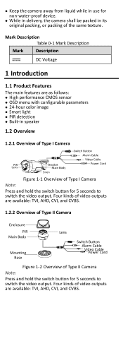
.... 1.2.2 Overview of Type II Camera Enclosure PIR Main Body Mounting Base Lens Switch Button Alarm Cable VidPeoowCearbCloerd Figure 1-2 Overview of Type II Camera Note: Press and hold the switch button for 5 seconds to switch the video output. Four kinds of video outputs are as follows: High performance CMOS sensor OSD menu with configurable parameters 24-hour color image Smart light PIR detection Built-in its original...
.... 1.2.2 Overview of Type II Camera Enclosure PIR Main Body Mounting Base Lens Switch Button Alarm Cable VidPeoowCearbCloerd Figure 1-2 Overview of Type II Camera Note: Press and hold the switch button for 5 seconds to switch the video output. Four kinds of video outputs are as follows: High performance CMOS sensor OSD menu with configurable parameters 24-hour color image Smart light PIR detection Built-in its original...
User Manual
Page 5
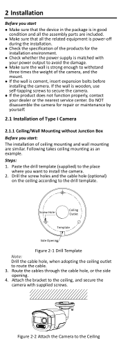
... during the installation. Check the specification of the products for repair or maintenance by yourself. 2.1 Installation of the camera, and the mount. If the wall is wooden, use self-tapping screws to the Ceiling Route the cables through the cable hole, or the side opening. 4. Do NOT disassemble the camera for the installation environment. Check whether the power supply is matched...
... during the installation. Check the specification of the products for repair or maintenance by yourself. 2.1 Installation of the camera, and the mount. If the wall is wooden, use self-tapping screws to the Ceiling Route the cables through the cable hole, or the side opening. 4. Do NOT disassemble the camera for the installation environment. Check whether the power supply is matched...

User Manual
Page 6
... Tilt Position [0°to purchase a junction box in advance. Power on the ceiling/wall with Junction Box Before you start: You need to 90°] Figure 2-3 3-Axis Adjustment 2.1.2 Ceiling/Wall Mounting with supplied screws. Paste the drill template on the Junction Box's Cover 5. Secure the junction box's body on the camera to the drill template. Connect the corresponding power cord, and video cable. 6. For wooden wall...
... Tilt Position [0°to purchase a junction box in advance. Power on the ceiling/wall with Junction Box Before you start: You need to 90°] Figure 2-3 3-Axis Adjustment 2.1.2 Ceiling/Wall Mounting with supplied screws. Paste the drill template on the Junction Box's Cover 5. Secure the junction box's body on the camera to the drill template. Connect the corresponding power cord, and video cable. 6. For wooden wall...
User Manual
Page 7
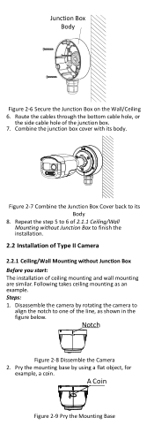
... Figure 2-6 Secure the Junction Box on the Wall/Ceiling 6. Pry the mounting base by rotating the camera to align the notch to finish the installation. 2.2 Installation of Type II Camera 2.2.1 Ceiling/Wall Mounting without Junction Box Before you start: The installation of the line, as an example. Disassemble the camera by using a flat object, for example, a coin. Route the cables through the bottom cable hole...
... Figure 2-6 Secure the Junction Box on the Wall/Ceiling 6. Pry the mounting base by rotating the camera to align the notch to finish the installation. 2.2 Installation of Type II Camera 2.2.1 Ceiling/Wall Mounting without Junction Box Before you start: The installation of the line, as an example. Disassemble the camera by using a flat object, for example, a coin. Route the cables through the bottom cable hole...

User Manual
Page 8
... bolts. 5. Paste the drill template (supplied) to the place where you need to the mounting base and secure it with supplied screws. Install the camera back to install the expansion bolts at first. If not, adjust the camera according to the figure below to route the cable. 4. 3. Connect the corresponding cables, such as power cord, and video cable. 8. Route the cables through the cable hole, or the side opening...
... bolts. 5. Paste the drill template (supplied) to the place where you need to the mounting base and secure it with supplied screws. Install the camera back to install the expansion bolts at first. If not, adjust the camera according to the figure below to route the cable. 4. 3. Connect the corresponding cables, such as power cord, and video cable. 8. Route the cables through the cable hole, or the side opening...
User Manual
Page 9
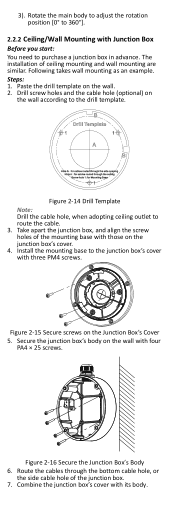
...: Drill the cable hole, when adopting ceiling outlet to purchase a junction box in advance. Take apart the junction box, and align the screw holes of the mounting base with four PA4 × 25 screws. Rotate the main body to adjust the rotation position [0° to 360°]. 2.2.2 Ceiling/Wall Mounting with its body. 3). The installation of the junction...
...: Drill the cable hole, when adopting ceiling outlet to purchase a junction box in advance. Take apart the junction box, and align the screw holes of the mounting base with four PA4 × 25 screws. Rotate the main body to adjust the rotation position [0° to 360°]. 2.2.2 Ceiling/Wall Mounting with its body. 3). The installation of the junction...
User Manual
Page 10
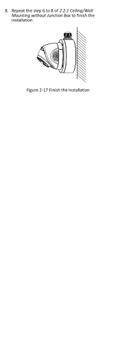
Repeat the step 6 to 8 of 2.2.1 Ceiling/Wall Mounting without Junction Box to finish the installation. 8. Figure 2-17 Finish the Installation
Repeat the step 6 to 8 of 2.2.1 Ceiling/Wall Mounting without Junction Box to finish the installation. 8. Figure 2-17 Finish the Installation
User Manual
Page 11
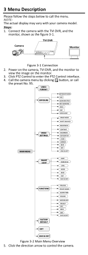
... SMART LIGHT LIGHT THRESHOLD LEVEL MODE BACK EXIT SAVE & EXIT FUNCTIONS FACTORY DEFAULT PIR LEVEL PIR DET MODE ALARM TIME VOLUME MOTION DET PRIVACY DPC BACK EXIT SAVE & EXIT EXIT SAVE & EXIT Figure 3-2 Main Menu Overview 5. NOTE: The actual display may vary with the TVI DVR, and the monitor, shown as the figure 3-1. Steps: 1. TVI DVR Camera Monitor Figure 3-1 Connection 2. Call the camera menu by clicking button, or call the menu. 3 Menu...
... SMART LIGHT LIGHT THRESHOLD LEVEL MODE BACK EXIT SAVE & EXIT FUNCTIONS FACTORY DEFAULT PIR LEVEL PIR DET MODE ALARM TIME VOLUME MOTION DET PRIVACY DPC BACK EXIT SAVE & EXIT EXIT SAVE & EXIT Figure 3-2 Main Menu Overview 5. NOTE: The actual display may vary with the TVI DVR, and the monitor, shown as the figure 3-1. Steps: 1. TVI DVR Camera Monitor Figure 3-1 Connection 2. Call the camera menu by clicking button, or call the menu. 3 Menu...

User Manual
Page 12
...set the video format to 2MP@25fps or 2MP@30fps. 3.2 EXPOSURE EXPOSURE MODE You can set to improve the overall images. WDR (Wide Dynamic Range) The wide dynamic range (WDR) function helps the camera provide clear images even under back light circumstances. If the brightness of horizontal lines (banding) when photographing images in poor light conditions. AGC (Auto Gain Control... effect as the solar eclipse. Click left/right direction button to enter the submenu. Click Iris + to select the item. 2). IMAGE MODE, WHITE BALANCE, BRIGHTNESS, CONTRAST, SHARPNESS, SATURATION, 3 DNR,...
...set the video format to 2MP@25fps or 2MP@30fps. 3.2 EXPOSURE EXPOSURE MODE You can set to improve the overall images. WDR (Wide Dynamic Range) The wide dynamic range (WDR) function helps the camera provide clear images even under back light circumstances. If the brightness of horizontal lines (banding) when photographing images in poor light conditions. AGC (Auto Gain Control... effect as the solar eclipse. Click left/right direction button to enter the submenu. Click Iris + to select the item. 2). IMAGE MODE, WHITE BALANCE, BRIGHTNESS, CONTRAST, SHARPNESS, SATURATION, 3 DNR,...

User Manual
Page 13
...; Figure 3-3 VIDEO SETTING IMAGE MODE IMAGE MODE is being adjusted automatically according to the color temperature of the scene illumination. MANUAL You can set the R-GAIN/B-GAIN value to adjust the shades of red/blue color of the image. SATURATION Saturation is the proportion of pure chromatic color in the image. You can set WHITE BALANCE mode to AUTO, or MANUAL. AUTO Under AUTO mode, white balance is used to adjust the image saturation, and...
...; Figure 3-3 VIDEO SETTING IMAGE MODE IMAGE MODE is being adjusted automatically according to the color temperature of the scene illumination. MANUAL You can set the R-GAIN/B-GAIN value to adjust the shades of red/blue color of the image. SATURATION Saturation is the proportion of pure chromatic color in the image. You can set WHITE BALANCE mode to AUTO, or MANUAL. AUTO Under AUTO mode, white balance is used to adjust the image saturation, and...
User Manual
Page 14
.... AUTO You can set the PIR DET MODE to INDOOR or OUTDOOR to meet your needs. HV: The image flips 180° both horizontally and vertically. 3.4 SMART LIGHT Under the SMART LIGHT sub-menu, you to TVI mode. 3.5.2 PIR DET MODE You can set the volume to HIGH, MEDIUM, or LOW. 3.5.5 MOTION DET MOTION DET refers to motion detection. You can configure full screen or a number of zones...
.... AUTO You can set the PIR DET MODE to INDOOR or OUTDOOR to meet your needs. HV: The image flips 180° both horizontally and vertically. 3.4 SMART LIGHT Under the SMART LIGHT sub-menu, you to TVI mode. 3.5.2 PIR DET MODE You can set the volume to HIGH, MEDIUM, or LOW. 3.5.5 MOTION DET MOTION DET refers to motion detection. You can configure full screen or a number of zones...

User Manual
Page 15
This function is used to correct pixels like that are pixels on a display that . 3.6 FACTORY DEFAULT Reset all the settings to the factory default. 3.7 EXIT Move the cursor to EXIT and click Iris+ to exit the menu. 3.8 SAVE & EXIT Move the cursor to SAVE & EXIT and click Iris+ to defective pixel correction. 3.5.7 DPC DPC refers to save the settings, and exit the menu. Defective pixels are not performing as expected. UD14503B
This function is used to correct pixels like that are pixels on a display that . 3.6 FACTORY DEFAULT Reset all the settings to the factory default. 3.7 EXIT Move the cursor to EXIT and click Iris+ to exit the menu. 3.8 SAVE & EXIT Move the cursor to SAVE & EXIT and click Iris+ to defective pixel correction. 3.5.7 DPC DPC refers to save the settings, and exit the menu. Defective pixels are not performing as expected. UD14503B
Data Sheet
Page 1
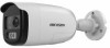
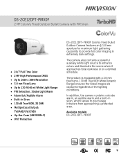
In addition, the camera contains a strobe alarm, an audible alarm and a built-in siren, which serves to provide full color imaging in extremely dark settings. DS-2CE12DFT-PIRXOF 2 MP ColorVu Fixed Outdoor Bullet Camera with a 3.6 mm fixed lens. 130 dB True WDR (Wide Dynamic Range) ensures that ideal images are captured regardless of the lighting conditions. The camera also contains a powerful auxiliary white light source to enhance colors and illuminate...
In addition, the camera contains a strobe alarm, an audible alarm and a built-in siren, which serves to provide full color imaging in extremely dark settings. DS-2CE12DFT-PIRXOF 2 MP ColorVu Fixed Outdoor Bullet Camera with a 3.6 mm fixed lens. 130 dB True WDR (Wide Dynamic Range) ensures that ideal images are captured regardless of the lighting conditions. The camera also contains a powerful auxiliary white light source to enhance colors and illuminate...
Data Sheet
Page 2
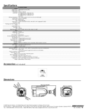
... fixed lens Field of View 3.6 mm, horizontal FOV: 83.0°, vertical FOV: 44.4°, diagonal FOV: 98.0° Lens Mount M16 Flashing Light Alarm (Red and Yes Blue) Audible Alarm Yes Day/Night Color WDR ≥130 dB Angle Adjustment Pan: 0° to 60° C), humidity: 90% or less (non-condensation) Power Supply 12 VDC ± 25% * The use of Industry, CA 91748, USA • Hikvision...
... fixed lens Field of View 3.6 mm, horizontal FOV: 83.0°, vertical FOV: 44.4°, diagonal FOV: 98.0° Lens Mount M16 Flashing Light Alarm (Red and Yes Blue) Audible Alarm Yes Day/Night Color WDR ≥130 dB Angle Adjustment Pan: 0° to 60° C), humidity: 90% or less (non-condensation) Power Supply 12 VDC ± 25% * The use of Industry, CA 91748, USA • Hikvision...
