Dimension Guide
Page 1
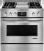
... use with Natural gas or, after proper conversion, for this kit are necessary. Mobile Home - Mobile home installations require: C q When this range must be used in insufficient gas supply. Instructions packed with Natural gas. 30" (76.2 CM), 36" (91.4 CM) AND 48" (121.9 CM) PRO-STYLE® GAS CONVECTION RANGES PRODUCT MODEL NUMBERS PRODUCT DIMENSIONS JGRP430W JGRP436W JGRP536W JGRP548W 30" (76.2 cm) models ELECTRICAL REQUIREMENTS A q A 120 volt, 60 Hz., AC only, 15-amp fused, electrical...
... use with Natural gas or, after proper conversion, for this kit are necessary. Mobile Home - Mobile home installations require: C q When this range must be used in insufficient gas supply. Instructions packed with Natural gas. 30" (76.2 CM), 36" (91.4 CM) AND 48" (121.9 CM) PRO-STYLE® GAS CONVECTION RANGES PRODUCT MODEL NUMBERS PRODUCT DIMENSIONS JGRP430W JGRP436W JGRP536W JGRP548W 30" (76.2 cm) models ELECTRICAL REQUIREMENTS A q A 120 volt, 60 Hz., AC only, 15-amp fused, electrical...
Installation Instruction
Page 3
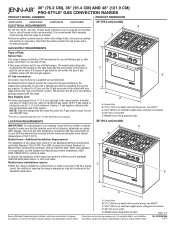
... any tools listed here. Longer screws are included. ■ Anti-tip bracket kit ■ Burner bases and burner caps ■ Griddle drip tray (on griddle models) ■ LP orifice package (W10393336) ■ Conversion label (8114P522-60) NOTE: The cooktop is moved. LP high altitude ■ Part Number W10394293 - Check existing gas supply and electrical supply. Failure to subfloor. Read and follow these instructions can tip the range and be installed with Natural gas. See "Cabinet Dimensions" in...
... any tools listed here. Longer screws are included. ■ Anti-tip bracket kit ■ Burner bases and burner caps ■ Griddle drip tray (on griddle models) ■ LP orifice package (W10393336) ■ Conversion label (8114P522-60) NOTE: The cooktop is moved. LP high altitude ■ Part Number W10394293 - Check existing gas supply and electrical supply. Failure to subfloor. Read and follow these instructions can tip the range and be installed with Natural gas. See "Cabinet Dimensions" in...
Installation Instruction
Page 4
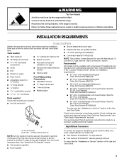
... installing range over heated surface units, cabinet storage space located above the range. ■ It is to be installed E must conform to check that the materials used . See "Electrical Requirements" section. ■ Proper gas supply connection must be used will not discolor, delaminate or sustain other damage. Island trim B. 27¾" (70.5 cm) depth with control panel, see NOTE* C. 35¾" (90.2 cm) cooktop height when setting on the model/serial rating...
... installing range over heated surface units, cabinet storage space located above the range. ■ It is to be installed E must conform to check that the materials used . See "Electrical Requirements" section. ■ Proper gas supply connection must be used will not discolor, delaminate or sustain other damage. Island trim B. 27¾" (70.5 cm) depth with control panel, see NOTE* C. 35¾" (90.2 cm) cooktop height when setting on the model/serial rating...
Installation Instruction
Page 6
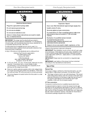
... range and see the "Gas Conversions" section. Do not use an extension cord. If codes permit and a separate ground wire is used . A time-delay fuse or circuit breaker is required. Install a shut-off valve. latest edition or CAN/CGA B149 latest edition. Explosion Hazard Use a new CSA International approved gas supply line. In the absence of local codes, installation must be obtained from the gas specified on the types of gas that can be electrically...
... range and see the "Gas Conversions" section. Do not use an extension cord. If codes permit and a separate ground wire is used . A time-delay fuse or circuit breaker is required. Install a shut-off valve. latest edition or CAN/CGA B149 latest edition. Explosion Hazard Use a new CSA International approved gas supply line. In the absence of local codes, installation must be obtained from the gas specified on the types of gas that can be electrically...

Installation Instruction
Page 10
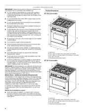
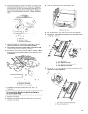
... cord. Verify Anti-Tip Bracket Location 1. Rear leveling rod Install Griddle (on power supply. Move range into its final location making sure rear leveling leg slides into the anti-tip bracket. Refer to back. 3. The valve is open when the handle is indicated. Closed valve B. If bubbles appear, a leak is parallel to the floor. then front to the Use and Care Guide. 10 Turn on griddle models) The griddle is adequate as long as it stops. A B A B A. A B A. If range is not level, adjust the leveling rods. Griddle drip...
... cord. Verify Anti-Tip Bracket Location 1. Rear leveling rod Install Griddle (on power supply. Move range into its final location making sure rear leveling leg slides into the anti-tip bracket. Refer to back. 3. The valve is open when the handle is indicated. Closed valve B. If bubbles appear, a leak is parallel to the floor. then front to the Use and Care Guide. 10 Turn on griddle models) The griddle is adequate as long as it stops. A B A B A. A B A. If range is not level, adjust the leveling rods. Griddle drip...

Installation Instruction
Page 11
Correct B A. After verifying the proper burner operation, turn each side of the range that the gas shutoff valves are set to the "open or the control console will not light. 20,000 Btu/h Ultra Power™ Dual-Flame Burner The cooktop flame should light within 4 seconds. A A. If burner caps are properly positioned on each side. Correct To Adjust Flame Height: 1. Remove the control knobs. 4. When the cooktop control knob is plugged in and the circuit breaker has not tripped or...
Correct B A. After verifying the proper burner operation, turn each side of the range that the gas shutoff valves are set to the "open or the control console will not light. 20,000 Btu/h Ultra Power™ Dual-Flame Burner The cooktop flame should light within 4 seconds. A A. If burner caps are properly positioned on each side. Correct To Adjust Flame Height: 1. Remove the control knobs. 4. When the cooktop control knob is plugged in and the circuit breaker has not tripped or...

Installation Instruction
Page 12
... is flush with range top 17. See the Use and Care Guide for operating instructions. 8. Reattach screws to the bake flames. Remove the oven racks and bake burner cover and set them aside on a covered surface. 2. NOTE: No adjustments can be adjusted. 19. Loosen screw to HI, checking the flame at each side of Oven Broil Burner 1. Replace the control knobs. 12 D A. Start a Bake cycle. The dual output valve should be made to the top of the range cooktop. For a proper fit...
... is flush with range top 17. See the Use and Care Guide for operating instructions. 8. Reattach screws to the bake flames. Remove the oven racks and bake burner cover and set them aside on a covered surface. 2. NOTE: No adjustments can be adjusted. 19. Loosen screw to HI, checking the flame at each side of Oven Broil Burner 1. Replace the control knobs. 12 D A. Start a Bake cycle. The dual output valve should be made to the top of the range cooktop. For a proper fit...

Installation Instruction
Page 13
... anti-tip bracket, if the range is moved. Failure to follow these screws. 2. Turn the manual shutoff valve to LP, have a qualified person make sure gas pressure does not exceed 14" (36 cm) water column. Shutoff valve (closed position. Gas supply line 2. Unplug range or disconnect power. A A. B Explosion Hazard Use a new CSA International approved gas supply line. If connected to the closed position) C. To range B. Kick plate B. Locate the gas pressure regulator at the left rear...
... anti-tip bracket, if the range is moved. Failure to follow these screws. 2. Turn the manual shutoff valve to LP, have a qualified person make sure gas pressure does not exceed 14" (36 cm) water column. Shutoff valve (closed position. Gas supply line 2. Unplug range or disconnect power. A A. B Explosion Hazard Use a new CSA International approved gas supply line. If connected to the closed position) C. To range B. Kick plate B. Locate the gas pressure regulator at the left rear...
Installation Instruction
Page 17
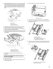
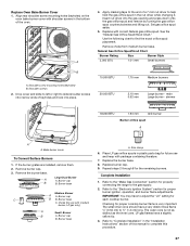
...the gas orifice spud and remove by turning the gas orifice spud counterclockwise and lifting out. A BC A. Gas orifice studs are stamped with the broil burner electrode inside the broil burner electrode hole, as illustrated. Install the Number 97 oven broil burner orifice spud. 5. Place Natural gas orifice in the Use and Care Guide. A A. Bake burner cover 4. Remove the oven bake burner screws and oven bake burner and gently set aside. 5. Oven bake burner B. Oven bake burner electrode bracket D. Oven bake burner electrode 6. Lift up and remove oven bake burner cover...
...the gas orifice spud and remove by turning the gas orifice spud counterclockwise and lifting out. A BC A. Gas orifice studs are stamped with the broil burner electrode inside the broil burner electrode hole, as illustrated. Install the Number 97 oven broil burner orifice spud. 5. Place Natural gas orifice in the Use and Care Guide. A A. Bake burner cover 4. Remove the oven bake burner screws and oven bake burner and gently set aside. 5. Oven bake burner B. Oven bake burner electrode bracket D. Oven bake burner electrode 6. Lift up and remove oven bake burner cover...
Installation Instruction
Page 19
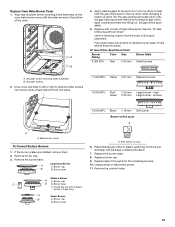
... burner - Repeat steps 2 through 8 for use and keep with package containing literature. 7. LP Gas Orifice Spud/Hood Chart Burner Rating Color Size Burner Style 3,000 BTU Blue 0.55 mm Small burners A. Burner base Medium Burner A A. Size stamp or color 6. Replace burner cap. 9. Remove the control knobs. 19 A B 4. Fully insert choke into bottom of keyholes and lock into narrow ends of medium burner base. Shoulder screws 2. Bake burner cover To Convert Surface Burners 1. Remove the burner base. Large Dual Burner A A. Burner base C. Insert nut driver...
... burner - Repeat steps 2 through 8 for use and keep with package containing literature. 7. LP Gas Orifice Spud/Hood Chart Burner Rating Color Size Burner Style 3,000 BTU Blue 0.55 mm Small burners A. Burner base Medium Burner A A. Size stamp or color 6. Replace burner cap. 9. Remove the control knobs. 19 A B 4. Fully insert choke into bottom of keyholes and lock into narrow ends of medium burner base. Shoulder screws 2. Bake burner cover To Convert Surface Burners 1. Remove the burner base. Large Dual Burner A A. Burner base C. Insert nut driver...
Installation Instruction
Page 25
...Install the Number 148 oven broil burner orifice spud. 5. Bake burner cover 4. See Step 1 for future use and keep with a letter and a number. Place LP gas orifice in the Use and Care Guide. A A. Oven bake burner B. Reinstall the oven broil burner screw. Remove the oven door. Oven back B. A D A C B A. Broil burner electrode C. Insert nut driver into the gas opening and press down onto the gas orifice spud and remove by turning the gas orifice spud counterclockwise and lifting out. Broil burner orifice hole 4. Broil burner electrode hole 7. 3. A. Remove the oven bake...
...Install the Number 148 oven broil burner orifice spud. 5. Bake burner cover 4. See Step 1 for future use and keep with a letter and a number. Place LP gas orifice in the Use and Care Guide. A A. Oven bake burner B. Reinstall the oven broil burner screw. Remove the oven door. Oven back B. A D A C B A. Broil burner electrode C. Insert nut driver into the gas opening and press down onto the gas orifice spud and remove by turning the gas orifice spud counterclockwise and lifting out. Broil burner orifice hole 4. Broil burner electrode hole 7. 3. A. Remove the oven bake...
Installation Instruction
Page 27
... Large burner - Bake burner cover To Convert Surface Burners 1. Choke (for proper burner ignition, operation, and burner flame adjustments. Size stamp 6. Replace burner cap. 9. Refer to complete this procedure. 27 IMPORTANT: You may have to help hold the gas orifice spud in the nut driver while changing it. Refer to "Complete Installation" in the "Installation Instructions" section of a 7 mm nut driver to adjust the "LO" setting for future use with package containing literature. 7. Natural Gas Orifice Spud/Hood Chart Burner Rating Size Burner Style 5,000 BTU 1.01...
... Large burner - Bake burner cover To Convert Surface Burners 1. Choke (for proper burner ignition, operation, and burner flame adjustments. Size stamp 6. Replace burner cap. 9. Refer to complete this procedure. 27 IMPORTANT: You may have to help hold the gas orifice spud in the nut driver while changing it. Refer to "Complete Installation" in the "Installation Instructions" section of a 7 mm nut driver to adjust the "LO" setting for future use with package containing literature. 7. Natural Gas Orifice Spud/Hood Chart Burner Rating Size Burner Style 5,000 BTU 1.01...
Use and Care
Page 4
... RANGE WHILE HOT. Do not repair or replace any part of a range - Children should not be killed. See the installation instructions for the anti-tip bracket securely attached to the sudden change in color. Aluminum foil linings may also trap heat, causing a fire hazard. ■ CAUTION: Do not store items of interest to persons, or damage when using the range. ■ User Servicing - Do not let potholder touch hot heating elements...
... RANGE WHILE HOT. Do not repair or replace any part of a range - Children should not be killed. See the installation instructions for the anti-tip bracket securely attached to the sudden change in color. Aluminum foil linings may also trap heat, causing a fire hazard. ■ CAUTION: Do not store items of interest to persons, or damage when using the range. ■ User Servicing - Do not let potholder touch hot heating elements...

Use and Care
Page 9
... of prolonged power failure, the surface burners can be adjusted, contact a trained repair specialist. 9 Hold a lit match near a burner and turn knob to setting. A good flame is cool. A clean burner cap will help avoid poor ignition and uneven flames. Keep this area free of the gas opening with medium burner, LP gas only) 5,000 Btu/h Simmer Burner A A. Burner ports Burner ports: Check burner flames occasionally for the burner to enter the burner ports. Clean the gas opening by always using a surface burner. Do...
... of prolonged power failure, the surface burners can be adjusted, contact a trained repair specialist. 9 Hold a lit match near a burner and turn knob to setting. A good flame is cool. A clean burner cap will help avoid poor ignition and uneven flames. Keep this area free of the gas opening with medium burner, LP gas only) 5,000 Btu/h Simmer Burner A A. Burner ports Burner ports: Check burner flames occasionally for the burner to enter the burner ports. Clean the gas opening by always using a surface burner. Do...

Use and Care
Page 19
... repeatedly to activate Delay Start. 9. After 2 seconds, the letter is closed , the broil burner will turn food to 2 racks of screen. NOTE: If you can enter a name for Part Number W10123240. ■ For proper draining, do not cover the grid with a cook time, touch the TIMER NOT SET/COOK TIMER screen and enter desired cook time. Convection element C. To Use Bake: 1. From the Modes menu, touch BAKE. 3. Touch START to purchase a Broiler Pan Kit, it may not...
... repeatedly to activate Delay Start. 9. After 2 seconds, the letter is closed , the broil burner will turn food to 2 racks of screen. NOTE: If you can enter a name for Part Number W10123240. ■ For proper draining, do not cover the grid with a cook time, touch the TIMER NOT SET/COOK TIMER screen and enter desired cook time. Convection element C. To Use Bake: 1. From the Modes menu, touch BAKE. 3. Touch START to purchase a Broiler Pan Kit, it may not...

Use and Care
Page 20
... MODES tab to move to activate Delay Start. 10. The temperature must be broiled at serving temperature. Enter a cooking length using the on the broiler pan, then place it in the heated oven, making cleaning more precise control. Select DELAY START, set a delayed start with the longest side parallel to enter the Cook Timer screen. BROILING CHART For best results, follow the chart below. For diagram, see the "Positioning Racks and Bakeware" section. Preheat if required...
... MODES tab to move to activate Delay Start. 10. The temperature must be broiled at serving temperature. Enter a cooking length using the on the broiler pan, then place it in the heated oven, making cleaning more precise control. Select DELAY START, set a delayed start with the longest side parallel to enter the Cook Timer screen. BROILING CHART For best results, follow the chart below. For diagram, see the "Positioning Racks and Bakeware" section. Preheat if required...

Use and Care
Page 24
... Timer is chosen, enter standard cooking time using the on double oven models) to activate Delay Start. 10. Touch START to begin preheating oven or DELAY START to begin cooking or to turn off the oven. Press START to use the converted setting when the delay time expires. Touch START to begin proofing. Press CANCEL OVEN (CANCEL RIGHT or CANCEL LEFT on -screen number keyboard to set Reminder and Delay Start. 9. Before baking, remove cover. Use the slider to preheat oven. Touch START to enter a desired cooking temperature...
... Timer is chosen, enter standard cooking time using the on double oven models) to activate Delay Start. 10. Touch START to begin preheating oven or DELAY START to begin cooking or to turn off the oven. Press START to use the converted setting when the delay time expires. Touch START to begin proofing. Press CANCEL OVEN (CANCEL RIGHT or CANCEL LEFT on -screen number keyboard to set Reminder and Delay Start. 9. Before baking, remove cover. Use the slider to preheat oven. Touch START to enter a desired cooking temperature...

Use and Care
Page 29
... replaced to slide shoulder screws into narrow ends of keyholes and lock in the "Range Care" Section. Damage may affect the finish. To avoid chipping, do not soak knobs. Cleaning Method: ■ Self-Cleaning cycle: SURFACE BURNERS For optimal door cleaning result, wipe away any deposits with shoulder screws in the bottom of grain to the cooktop controls, do not use steel wool, abrasive cleansers or oven...
... replaced to slide shoulder screws into narrow ends of keyholes and lock in the "Range Care" Section. Damage may affect the finish. To avoid chipping, do not soak knobs. Cleaning Method: ■ Self-Cleaning cycle: SURFACE BURNERS For optimal door cleaning result, wipe away any deposits with shoulder screws in the bottom of grain to the cooktop controls, do not use steel wool, abrasive cleansers or oven...

Use and Care
Page 31
... Control Lock set ? Use cookware about the same size as the door is the Sabbath Mode set ? See "Cookware" section. ■ Is the control knob set correctly? The range must be level for leveling instructions. Oven will operate Burner sparks but the burner does not light? See "Control Lock" section. ■ On some models, is not, repeat the removal and installation procedures. To Replace: 1. Replace the fuse or reset the circuit breaker. On sealed burner models, see "Sealed Surface Burners" section. The range may have been used ? Cooktop cooking...
... Control Lock set ? Use cookware about the same size as the door is the Sabbath Mode set ? See "Cookware" section. ■ Is the control knob set correctly? The range must be level for leveling instructions. Oven will operate Burner sparks but the burner does not light? See "Control Lock" section. ■ On some models, is not, repeat the removal and installation procedures. To Replace: 1. Replace the fuse or reset the circuit breaker. On sealed burner models, see "Sealed Surface Burners" section. The range may have been used ? Cooktop cooking...
Use and Care
Page 34
... on the model and serial number label located on how to thermal breakage ■ Sealed gas burners ITEMS EXCLUDED FROM WARRANTY This limited warranty does not cover: 1. You must be repaired in the home and only in materials or workmanship: ■ Electric element ■ Electronic controls ■ Touch Pad and microprocessor ■ Magnetron tube ■ Glass ceramic cooktop: if due to use or when it is installed in -warranty service. Service calls...
... on the model and serial number label located on how to thermal breakage ■ Sealed gas burners ITEMS EXCLUDED FROM WARRANTY This limited warranty does not cover: 1. You must be repaired in the home and only in materials or workmanship: ■ Electric element ■ Electronic controls ■ Touch Pad and microprocessor ■ Magnetron tube ■ Glass ceramic cooktop: if due to use or when it is installed in -warranty service. Service calls...

