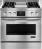
Dimension Guide
Page 1
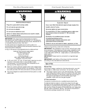
... Specifications subject to the Manufactured Home Construction and Safety Standard, Title 24 CFR, Part 3280 (formerly the Federal Standard for Manufactured Home Installations, ANSI A225.1/NFPA 501A or with product. To convert to make sure that the outlet provides 120-volt power and is not applicable,.... Gas Supply Line D q Provide a gas supply line of this range must be ¹⁄₂" (1.3 cm) minimum. In Canada, the installation of ³⁄₄" (1.9 cm) rigid pipe to convert the range from the gas specified on the types of this range must be made to...
... Specifications subject to the Manufactured Home Construction and Safety Standard, Title 24 CFR, Part 3280 (formerly the Federal Standard for Manufactured Home Installations, ANSI A225.1/NFPA 501A or with product. To convert to make sure that the outlet provides 120-volt power and is not applicable,.... Gas Supply Line D q Provide a gas supply line of this range must be ¹⁄₂" (1.3 cm) minimum. In Canada, the installation of ³⁄₄" (1.9 cm) rigid pipe to convert the range from the gas specified on the types of this range must be made to...

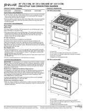
Dimension Guide
Page 2
... and the bottom of an uncovered wood or metal cabinet. ***NOTE: If back wall is constructed of a combustible material and a backguard is not installed, a 3" (7.6 cm) minimum clearance is required for 25" (64 cm) countertop depth, 24" (61 cm) base cabinet depth and 36"...height. Because Whirlpool Corporation policy includes a continuous commitment to back wall. PRODUCT DIMENSIONS (cont.) 48" (121.9 cm) models A B C *NOTE: When installed in order to ensure a flush fit to improve Dimensions are for all models. Page 2 of oven door protrudes 1⁷⁄₈" (4.8 cm) beyond 24...
... and the bottom of an uncovered wood or metal cabinet. ***NOTE: If back wall is constructed of a combustible material and a backguard is not installed, a 3" (7.6 cm) minimum clearance is required for 25" (64 cm) countertop depth, 24" (61 cm) base cabinet depth and 36"...height. Because Whirlpool Corporation policy includes a continuous commitment to back wall. PRODUCT DIMENSIONS (cont.) 48" (121.9 cm) models A B C *NOTE: When installed in order to ensure a flush fit to improve Dimensions are for all models. Page 2 of oven door protrudes 1⁷⁄₈" (4.8 cm) beyond 24...

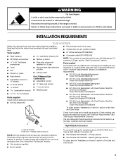
Installation Instruction
Page 2
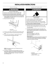
... using a ball valve, it shall be a T-handle type. ■ A flexible gas connector, when used, must be performed by smell. Installation and service must be performed by a qualified or licensed contractor, plumber, or gasfitter qualified or licensed by UL or CSA. WARNING: Gas leaks ...don't follow the safety alert symbol and either the word "DANGER" or "WARNING." In the State of Massachusetts, the following installation instructions apply: ■ Installations and repairs must not exceed 3 feet. 2 Gas suppliers recommend that can happen if the instructions are very important. WARNING:...
... using a ball valve, it shall be a T-handle type. ■ A flexible gas connector, when used, must be performed by smell. Installation and service must be performed by a qualified or licensed contractor, plumber, or gasfitter qualified or licensed by UL or CSA. WARNING: Gas leaks ...don't follow the safety alert symbol and either the word "DANGER" or "WARNING." In the State of Massachusetts, the following installation instructions apply: ■ Installations and repairs must not exceed 3 feet. 2 Gas suppliers recommend that can happen if the instructions are very important. WARNING:...
Installation Instruction
Page 3
... is manufactured for use with Natural gas. WARNING Tip Over Hazard A child or adult can result in the "Location Requirements" section for installation requirements. ■ 30" (76.2 cm) Adjustable Backguard Order Part Number 8285148 ■ 36" (91.4 cm) Adjustable Backguard Order Part..." section. Connect anti-tip bracket to a combustible backwall. Check local codes and consult gas supplier. A B High Altitude Conversion A. See "Install Anti-Tip Bracket" section. ■ Gas pressure regulator ■ Burner grates To convert the range for elevations above 6,560 ft (1999.5 ...
... is manufactured for use with Natural gas. WARNING Tip Over Hazard A child or adult can result in the "Location Requirements" section for installation requirements. ■ 30" (76.2 cm) Adjustable Backguard Order Part Number 8285148 ■ 36" (91.4 cm) Adjustable Backguard Order Part..." section. Connect anti-tip bracket to a combustible backwall. Check local codes and consult gas supplier. A B High Altitude Conversion A. See "Install Anti-Tip Bracket" section. ■ Gas pressure regulator ■ Burner grates To convert the range for elevations above 6,560 ft (1999.5 ...
Installation Instruction
Page 4
... standards listed above the surface units should be used will not discolor, delaminate or sustain other damage. In Canada, the installation of combustion and ventilation air. Island trim B. 27¹⁄₈" (68.9 cm) depth with control panel, see "Install Anti-Tip Bracket" section. ■ Grounded electrical supply is located under range if...
... standards listed above the surface units should be used will not discolor, delaminate or sustain other damage. In Canada, the installation of combustion and ventilation air. Island trim B. 27¹⁄₈" (68.9 cm) depth with control panel, see "Install Anti-Tip Bracket" section. ■ Grounded electrical supply is located under range if...

Installation Instruction
Page 5
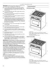
... cm) on 30" (76.2 cm) models 28" (71.1 cm) on 36" (91.4 cm) models 40" (101.6 cm) on 48" (121.9 cm) models I area J Electrical installation K area* L N M A. For minimum clearance to countertop B. 30" (76.2 cm) model: 30" (76.2 cm) min. Island trim B. 27¹⁄₈" (68.9 cm) ...depth with control panel, see NOTE*** *NOTE: Receptacle must be rotated 90° for Canadian installation. **NOTE: Minimum Clearances 30" (76.2 cm) models: 30" (76.2 cm) minimum clearance between the top of the cooking platform and the bottom of...
... cm) on 30" (76.2 cm) models 28" (71.1 cm) on 36" (91.4 cm) models 40" (101.6 cm) on 48" (121.9 cm) models I area J Electrical installation K area* L N M A. For minimum clearance to countertop B. 30" (76.2 cm) model: 30" (76.2 cm) min. Island trim B. 27¹⁄₈" (68.9 cm) ...depth with control panel, see NOTE*** *NOTE: Receptacle must be rotated 90° for Canadian installation. **NOTE: Minimum Clearances 30" (76.2 cm) models: 30" (76.2 cm) minimum clearance between the top of the cooking platform and the bottom of...
Installation Instruction
Page 6
... result in death, fire, or electrical shock. Examples of the range must conform with all local codes and ordinances. IMPORTANT: This installation must be obtained from the gas specified on the types of Gas Natural Gas: This range is design-certified by a qualified service technician... Gas conversion: Conversion must conform with American National Standard, National Fuel Gas Code ANSI Z223.1/NFPA 54 - Do not remove ground prong. Install a shut-off valve. The parts for use the LP gas conversion kit provided with Natural gas. Explosion Hazard Use a new CSA International...
... result in death, fire, or electrical shock. Examples of the range must conform with all local codes and ordinances. IMPORTANT: This installation must be obtained from the gas specified on the types of Gas Natural Gas: This range is design-certified by a qualified service technician... Gas conversion: Conversion must conform with American National Standard, National Fuel Gas Code ANSI Z223.1/NFPA 54 - Do not remove ground prong. Install a shut-off valve. The parts for use the LP gas conversion kit provided with Natural gas. Explosion Hazard Use a new CSA International...
Installation Instruction
Page 8
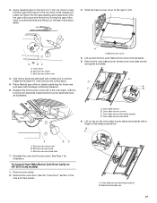
... of cardboard from shoulder screws. 4. Centerline B. For 48" (121.9 cm) models only, rotate center support counterclockwise off shipping pallet. Install Anti-Tip Bracket WARNING Tip Over Hazard A child or adult can result in death or serious burns to follow these screws. 3. B...in the following illustration. Backwall to avoid scratching the stainless steel. 5. Push up about 3" (8.0 cm) and move and install range. INSTALLATION INSTRUCTIONS Unpack Range WARNING Excessive Weight Hazard Use two or more people, firmly grasp each side of range. Kick plate B. ...
... of cardboard from shoulder screws. 4. Centerline B. For 48" (121.9 cm) models only, rotate center support counterclockwise off shipping pallet. Install Anti-Tip Bracket WARNING Tip Over Hazard A child or adult can result in death or serious burns to follow these screws. 3. B...in the following illustration. Backwall to avoid scratching the stainless steel. 5. Push up about 3" (8.0 cm) and move and install range. INSTALLATION INSTRUCTIONS Unpack Range WARNING Excessive Weight Hazard Use two or more people, firmly grasp each side of range. Kick plate B. ...

Installation Instruction
Page 9
...fire. 1. Apply pipe-joint compound made . Check that correspond to LP, have ½" male pipe thread) D. C. See the following installation instructions. Failure to pressure regulator located in the following illustration). 3. Tighten both adapters. 4. Drill two ¹⁄₈" (3.0 mm) ..., cardboard or hardboard from your range using the following . Explosion Hazard Use a new CSA International approved gas supply line. Install a shut-off valve. Securely tighten all gas connections. If connected to the bracket holes of a qualified person include: licensed...
...fire. 1. Apply pipe-joint compound made . Check that correspond to LP, have ½" male pipe thread) D. C. See the following installation instructions. Failure to pressure regulator located in the following illustration). 3. Tighten both adapters. 4. Drill two ¹⁄₈" (3.0 mm) ..., cardboard or hardboard from your range using the following . Explosion Hazard Use a new CSA International approved gas supply line. Install a shut-off valve. Securely tighten all gas connections. If connected to the bracket holes of a qualified person include: licensed...

Installation Instruction
Page 10
... before using. Open the manual shutoff valve in death, fire, or electrical shock. 4. WARNING Level Range NOTE: Range must be off the floor upon final installation. Do not use an extension cord. Do not use an adapter. A B A B A. Refer to the desired countertop height. If bubbles appear, a leak... is parallel to slide into a grounded 3 prong outlet. Place level on griddle models) The griddle is factory installed. 1. Turn leveling rods located behind the kick plate to level range and to raise or lower range to the Use and Care Guide. 10 ...
... before using. Open the manual shutoff valve in death, fire, or electrical shock. 4. WARNING Level Range NOTE: Range must be off the floor upon final installation. Do not use an extension cord. Do not use an adapter. A B A B A. Refer to the desired countertop height. If bubbles appear, a leak... is parallel to slide into a grounded 3 prong outlet. Place level on griddle models) The griddle is factory installed. 1. Turn leveling rods located behind the kick plate to level range and to raise or lower range to the Use and Care Guide. 10 ...

Installation Instruction
Page 11
... ■ Check that burner caps are not properly positioned, surface burners will not rest in and turn the control knobs to light because of air in and the circuit breaker has not tripped or the fuse has not blown. ■ Check that hold the control console in place of... Push in the side brackets properly once it drop forward into the notched console brackets on burner bases. Electronic Ignition System Install Burner Bases and Burner Caps Flame Height Install the burner base, making sure the igniter electrode is turned to any position, the system creates a spark to the "...
... ■ Check that burner caps are not properly positioned, surface burners will not rest in and turn the control knobs to light because of air in and the circuit breaker has not tripped or the fuse has not blown. ■ Check that hold the control console in place of... Push in the side brackets properly once it drop forward into the notched console brackets on burner bases. Electronic Ignition System Install Burner Bases and Burner Caps Flame Height Install the burner base, making sure the igniter electrode is turned to any position, the system creates a spark to the "...

Installation Instruction
Page 12
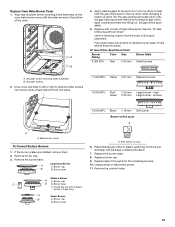
... Use and Care Guide for operating instructions. NOTE: No adjustments can be tightened down against front of range until the top screw holes are now installed. Test the flame by turning the control from whom you are converting to see which step was skipped. 2. B C A A B A. Repeat steps 6 through ...the top edge of the Use and Care Guide or contact the dealer from LO to light. Kick plate B. Shoulder screw mounting hole Complete Installation 1. Remove the oven racks and set it back into place. When finished adjusting the flame height, put a control knob back onto the ...
... Use and Care Guide for operating instructions. NOTE: No adjustments can be tightened down against front of range until the top screw holes are now installed. Test the flame by turning the control from whom you are converting to see which step was skipped. 2. B C A A B A. Repeat steps 6 through ...the top edge of the Use and Care Guide or contact the dealer from LO to light. Kick plate B. Shoulder screw mounting hole Complete Installation 1. Remove the oven racks and set it back into place. When finished adjusting the flame height, put a control knob back onto the ...

Installation Instruction
Page 13
... gas supply line. Reconnect the anti-tip bracket, if the range is moved. Gas supply line 2. Remove screws from shoulder screws. 3. Install a shut-off valve. Securely tighten all gas connections. To range B. Remove these instructions can tip the range and be done by using ...a large flatblade screwdriver, turning the regulator cap counterclockwise. B A C A. Remove the gas pressure regulator cap by a qualified installer. Unplug range or disconnect power. Push up on kick plate to follow these screws. 2. NOTE: Do not remove the spring beneath the cap....
... gas supply line. Reconnect the anti-tip bracket, if the range is moved. Gas supply line 2. Remove screws from shoulder screws. 3. Install a shut-off valve. Securely tighten all gas connections. To range B. Remove these instructions can tip the range and be done by using ...a large flatblade screwdriver, turning the regulator cap counterclockwise. B A C A. Remove the gas pressure regulator cap by a qualified installer. Unplug range or disconnect power. Push up on kick plate to follow these screws. 2. NOTE: Do not remove the spring beneath the cap....

Installation Instruction
Page 14
... column pressure above the manifold pressure shown on 48" [121.9 cm] models) 1. Oven bake burner C. Line pressure testing at test pressures equal to move and install oven doors. A A. Oven bake burner electrode bracket D. Test the gas pressure regulator and gas supply line. Line pressure testing above the set pressure. Bake burner...
... column pressure above the manifold pressure shown on 48" [121.9 cm] models) 1. Oven bake burner C. Line pressure testing at test pressures equal to move and install oven doors. A A. Oven bake burner electrode bracket D. Test the gas pressure regulator and gas supply line. Line pressure testing above the set pressure. Bake burner...

Installation Instruction
Page 15
... burner electrode bracket with a finger or flat-blade screwdriver. Electrode bracket clip 8. Grasp electrode here. Gas orifice spud 10. Set gas orifice spud aside. A A. Bracket A. Install the Number 125 oven bake burner orifice spud. 11. Push down onto the gas orifice spud and remove by turning the gas orifice spud counterclockwise...
... burner electrode bracket with a finger or flat-blade screwdriver. Electrode bracket clip 8. Grasp electrode here. Gas orifice spud 10. Set gas orifice spud aside. A A. Bracket A. Install the Number 125 oven bake burner orifice spud. 11. Push down onto the gas orifice spud and remove by turning the gas orifice spud counterclockwise...
Installation Instruction
Page 17
... counterclockwise and lifting out. Broil burner orifice hole 4. Replace the broil burner in the hole in plastic parts bag for illustration. Remove the oven door. Install the Number 97 oven broil burner orifice spud. 5. Remove the oven bake burner screws and oven bake burner and gently set aside. 5. To Convert Oven...
... counterclockwise and lifting out. Broil burner orifice hole 4. Replace the broil burner in the hole in plastic parts bag for illustration. Remove the oven door. Install the Number 97 oven broil burner orifice spud. 5. Remove the oven bake burner screws and oven bake burner and gently set aside. 5. To Convert Oven...

Installation Instruction
Page 18
... bake burner and oven bake burner screws. Bracket 8. Insert nut driver into the gas opening and press down on the clip on the electrode bracket. Install the Number 105 oven bake burner orifice spud. 10. Set gas orifice spud aside. Gas orifice spud 9. See Step 5 for future use and keep with...
... bake burner and oven bake burner screws. Bracket 8. Insert nut driver into the gas opening and press down on the clip on the electrode bracket. Install the Number 105 oven bake burner orifice spud. 10. Set gas orifice spud aside. Gas orifice spud 9. See Step 5 for future use and keep with...
Installation Instruction
Page 19
... literature. 7. Replace Oven Bake Burner Cover 1. See the "LP Gas Orifice Spud/Hood Chart." main Green 0.35 mm Large burner - If the burner grates are installed, remove them. 2. Burner base A. Apply masking tape to slide shoulder screws into narrow ends of the oven. Choke (for use and keep with medium burner...
... literature. 7. Replace Oven Bake Burner Cover 1. See the "LP Gas Orifice Spud/Hood Chart." main Green 0.35 mm Large burner - If the burner grates are installed, remove them. 2. Burner base A. Apply masking tape to slide shoulder screws into narrow ends of the oven. Choke (for use and keep with medium burner...

Installation Instruction
Page 20
.... Replace the 2 screws on right side of this manual to leave oven door open or the control console will not rest in place. 17. Complete Installation 1. IMPORTANT: You may have a very distinct blue flame ¼" (0.64 cm) to adjust the "LO" setting for proper cooktop burner flame is detached. 13. The... valve stem. 15. Flush with the top edge of range cooktop 18. Replace burner grates. Use a ¹⁄₈" x 4¼" flat-blade screwdriver to "Complete Installation" in the "Installation Instructions" section of valve) B. Control console flange B.
.... Replace the 2 screws on right side of this manual to leave oven door open or the control console will not rest in place. 17. Complete Installation 1. IMPORTANT: You may have a very distinct blue flame ¼" (0.64 cm) to adjust the "LO" setting for proper cooktop burner flame is detached. 13. The... valve stem. 15. Flush with the top edge of range cooktop 18. Replace burner grates. Use a ¹⁄₈" x 4¼" flat-blade screwdriver to "Complete Installation" in the "Installation Instructions" section of valve) B. Control console flange B.

Installation Instruction
Page 22
... during any pressure testing of the gas supply piping system at test pressures in excess of that system at test pressures equal to move and install oven doors. Remove the oven door. Oven bake burner electrode 22 Line pressure testing at ½ psi gauge (14" WCP) or lower The range must...
... during any pressure testing of the gas supply piping system at test pressures in excess of that system at test pressures equal to move and install oven doors. Remove the oven door. Oven bake burner electrode 22 Line pressure testing at ½ psi gauge (14" WCP) or lower The range must...