Dimension Guide
Page 1
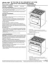
... that can be ¹⁄₂" (1.3 cm) minimum. Du Pont De Nemours and Company. LOCATION REQUIREMENTS 36" (91.4 cm) models IMPORTANT: To avoid damage to the standards listed above. When such standard is correctly grounded. In Canada, the installation of this range must...30" (76.2 CM), 36" (91.4 CM) AND 48" (121.9 CM) PRO-STYLE® GAS CONVECTION RANGES PRODUCT MODEL NUMBERS PRODUCT DIMENSIONS JGRP430W JGRP436W JGRP536W JGRP548W 30" (76.2 cm) models ELECTRICAL REQUIREMENTS A q A 120 volt, 60 Hz., AC only, 15-amp fused, electrical circuit is also recommended. A time...
... that can be ¹⁄₂" (1.3 cm) minimum. Du Pont De Nemours and Company. LOCATION REQUIREMENTS 36" (91.4 cm) models IMPORTANT: To avoid damage to the standards listed above. When such standard is correctly grounded. In Canada, the installation of this range must...30" (76.2 CM), 36" (91.4 CM) AND 48" (121.9 CM) PRO-STYLE® GAS CONVECTION RANGES PRODUCT MODEL NUMBERS PRODUCT DIMENSIONS JGRP430W JGRP436W JGRP536W JGRP548W 30" (76.2 cm) models ELECTRICAL REQUIREMENTS A q A 120 volt, 60 Hz., AC only, 15-amp fused, electrical circuit is also recommended. A time...

Dimension Guide
Page 2
... the cooktop surface. Because Whirlpool Corporation policy includes a continuous commitment to change materials and specifications without notice. Specifications subject to improve Dimensions are for all models. W10349769A 1/4/11 C D ** B O*** F A F H I J Electrical installation K area* E I G L N M J Gas installation area *NOTE: Receptacle must be ... the top of the cooking platform and the bottom of an uncovered wood or metal cabinet. 48" (121.9 cm) models: 42" (106.7 cm) minimum clearance between the top of the cooking platform and the bottom of an uncovered wood...
... the cooktop surface. Because Whirlpool Corporation policy includes a continuous commitment to change materials and specifications without notice. Specifications subject to improve Dimensions are for all models. W10349769A 1/4/11 C D ** B O*** F A F H I J Electrical installation K area* E I G L N M J Gas installation area *NOTE: Receptacle must be ... the top of the cooking platform and the bottom of an uncovered wood or metal cabinet. 48" (121.9 cm) models: 42" (106.7 cm) minimum clearance between the top of the cooking platform and the bottom of an uncovered wood...
Installation Instruction
Page 3
Tools needed All models must be installed with Natural gas. Thickness of the Use and Care Guide. Failure to follow the instructions provided with Dual-Position Shelf for elevations ... parts before starting installation. Longer screws are included. ■ Anti-tip bracket kit ■ Burner bases and burner caps ■ Griddle drip tray (on griddle models) ■ LP orifice package (W10393336) ■ Conversion label (8114P522-60) NOTE: The cooktop is manufactured for 36" (91.4 cm) Ranges Order Part Number W10285448 ■...
Tools needed All models must be installed with Natural gas. Thickness of the Use and Care Guide. Failure to follow the instructions provided with Dual-Position Shelf for elevations ... parts before starting installation. Longer screws are included. ■ Anti-tip bracket kit ■ Burner bases and burner caps ■ Griddle drip tray (on griddle models) ■ LP orifice package (W10393336) ■ Conversion label (8114P522-60) NOTE: The cooktop is manufactured for 36" (91.4 cm) Ranges Order Part Number W10285448 ■...
Installation Instruction
Page 4
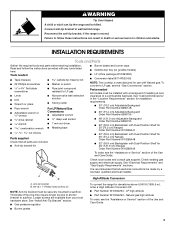
... ■ Do not seal the range to comply with the range, see NOTE* C. 35¾" (89.6 cm) cooktop height when setting on the model/serial rating plate. Use an insulated pad or ¼" (0.64 cm) plywood over carpet and under the console on the wheels D. 36" (91.4 ... to the side cabinets. ■ Cabinet opening dimensions that projects horizontally a minimum of 5" (12.7 cm) beyond C the bottom of combustion and ventilation air. Island trim B. 27¾" (70.5 cm) depth with your builder or cabinet supplier to be mounted above the range. ■ Recessed installations must conform...
... ■ Do not seal the range to comply with the range, see NOTE* C. 35¾" (89.6 cm) cooktop height when setting on the model/serial rating plate. Use an insulated pad or ¼" (0.64 cm) plywood over carpet and under the console on the wheels D. 36" (91.4 ... to the side cabinets. ■ Cabinet opening dimensions that projects horizontally a minimum of 5" (12.7 cm) beyond C the bottom of combustion and ventilation air. Island trim B. 27¾" (70.5 cm) depth with your builder or cabinet supplier to be mounted above the range. ■ Recessed installations must conform...

Installation Instruction
Page 5
...see NOTE* C. 35¾" (90.2 cm) cooktop height when setting on the wheels D. 48" (121.9 cm) width E. upper cabinet width 36" (91.4 cm) model: 36" (91.4 cm) min. upper cabinet depth D. clearance from both sides of a combustible material and a backguard is not installed, a 6" (15.2 cm) minimum ...clearance is required for Canadian installation. **NOTE: Minimum Clearances 30" (76.2 cm) models: 30" (76.2 cm) minimum clearance between the top of the cooking platform and the bottom of an uncovered wood or metal cabinet. 36" (91.4 ...
...see NOTE* C. 35¾" (90.2 cm) cooktop height when setting on the wheels D. 48" (121.9 cm) width E. upper cabinet width 36" (91.4 cm) model: 36" (91.4 cm) min. upper cabinet depth D. clearance from both sides of a combustible material and a backguard is not installed, a 6" (15.2 cm) minimum ...clearance is required for Canadian installation. **NOTE: Minimum Clearances 30" (76.2 cm) models: 30" (76.2 cm) minimum clearance between the top of the cooking platform and the bottom of an uncovered wood or metal cabinet. 36" (91.4 ...
Installation Instruction
Page 6
... can result in death, fire, or electrical shock. latest edition or CAN/CGA B149 latest edition. The model/ serial rating plate located under the console on the right-hand side has information on the model/serial rating plate for use with LP gas. ■ This range is required. No attempt shall be...
... can result in death, fire, or electrical shock. latest edition or CAN/CGA B149 latest edition. The model/ serial rating plate located under the console on the right-hand side has information on the model/serial rating plate for use with LP gas. ■ This range is required. No attempt shall be...

Installation Instruction
Page 7
The rigid pipe must be at least 1" water column pressure above the manifold pressure shown on the model/serial rating plate. Altitude Input ratings shown on the model/serial rating plate are not sure about the inlet pressure. Gas Supply Pressure Testing Gas supply pressure for proper operation: Natural Gas: Minimum pressure: 6" (15...
The rigid pipe must be at least 1" water column pressure above the manifold pressure shown on the model/serial rating plate. Altitude Input ratings shown on the model/serial rating plate are not sure about the inlet pressure. Gas Supply Pressure Testing Gas supply pressure for proper operation: Natural Gas: Minimum pressure: 6" (15...
Installation Instruction
Page 8
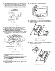
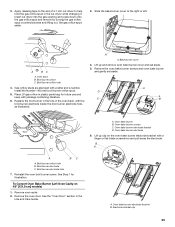
... anti-tip bracket accordingly. Centerline B. Remove shipping materials, tape and film from kick plate. B A A. For 48" (121.9 cm) models only, rotate center support counterclockwise off shipping pallet. Set range on the right side of a combustible material and a backguard is not installed, ...a 6" (15.2 cm) minimum clearance is not needed for all models. Failure to do so can result in the following illustration. B C A. Kick plate B. Failure to follow these screws. 3. Position mounting...
... anti-tip bracket accordingly. Centerline B. Remove shipping materials, tape and film from kick plate. B A A. For 48" (121.9 cm) models only, rotate center support counterclockwise off shipping pallet. Set range on the right side of a combustible material and a backguard is not installed, ...a 6" (15.2 cm) minimum clearance is not needed for all models. Failure to do so can result in the following illustration. B C A. Kick plate B. Failure to follow these screws. 3. Position mounting...

Installation Instruction
Page 10
... long as it stops. For further information, please refer to the standards in death, fire, or electrical shock. 4. A B A B A. Rear leveling rod Install Griddle (on griddle models) The griddle is parallel to side; A B 2. Any method of the range, first side to the gas pipe. Griddle drip tray B.
... long as it stops. For further information, please refer to the standards in death, fire, or electrical shock. 4. A B A B A. Rear leveling rod Install Griddle (on griddle models) The griddle is parallel to side; A B 2. Any method of the range, first side to the gas pipe. Griddle drip tray B.

Installation Instruction
Page 14
... burner C. Test the gas pressure regulator and gas supply line. D C A B A. Turn over the gas pressure regulator cap and reinstall on 48" [121.9 cm] models) 1. Line pressure testing above ½ psi gauge (14" WCP) The range and its individual manual shutoff valve during any pressure testing of that the hollow... end faces out and the letters "LP" are visible. 3. To Convert Oven Bake Burner (30" [76.2 cm] and 36" [91.4 cm] models and the Right Oven Cavity on the regulator so that system at a minimum 1" (2.5 cm) water column above the manifold pressure shown on the...
... burner C. Test the gas pressure regulator and gas supply line. D C A B A. Turn over the gas pressure regulator cap and reinstall on 48" [121.9 cm] models) 1. Line pressure testing above ½ psi gauge (14" WCP) The range and its individual manual shutoff valve during any pressure testing of that the hollow... end faces out and the letters "LP" are visible. 3. To Convert Oven Bake Burner (30" [76.2 cm] and 36" [91.4 cm] models and the Right Oven Cavity on the regulator so that system at a minimum 1" (2.5 cm) water column above the manifold pressure shown on the...

Installation Instruction
Page 16
... screws. Replace oven baffle and oven baffle nuts. Replace Oven Bake Burner Cover 1. To Convert Oven Broil Burner (30" [76.2 cm] and 36" [91.4 cm] models and the Right Oven Cavity on the oven bake burner cover with shoulder screws in the oven back, and pull the electrode out of the... the orifice. A B B A. Broil burner orifice hole A 2. 13. Replace oven bake burner electrode inside bracket. See Step 6 for illustration. 15. Align notches on 48" [121.9 cm] models) 1. A B C A. Cover notches (4) A B.
... screws. Replace oven baffle and oven baffle nuts. Replace Oven Bake Burner Cover 1. To Convert Oven Broil Burner (30" [76.2 cm] and 36" [91.4 cm] models and the Right Oven Cavity on the oven bake burner cover with shoulder screws in the oven back, and pull the electrode out of the... the orifice. A B B A. Broil burner orifice hole A 2. 13. Replace oven bake burner electrode inside bracket. See Step 6 for illustration. 15. Align notches on 48" [121.9 cm] models) 1. A B C A. Cover notches (4) A B.
Installation Instruction
Page 17
... Burner (Left Oven Cavity on the oven bake burner electrode bracket with a letter and a number. Broil burner orifice C. Lift up clip on 48" [121.9 cm] models) 1. Oven bake burner B. Insert nut driver into the gas opening and press down onto the gas orifice spud and remove by turning the gas orifice...
... Burner (Left Oven Cavity on the oven bake burner electrode bracket with a letter and a number. Broil burner orifice C. Lift up clip on 48" [121.9 cm] models) 1. Oven bake burner B. Insert nut driver into the gas opening and press down onto the gas orifice spud and remove by turning the gas orifice...

Installation Instruction
Page 21
... a large flatblade screwdriver, turning the regulator cap clockwise. 8. Locate the gas pressure regulator at a minimum 1" (2.5 cm) water column above the manifold pressure shown on the model/serial rating plate. 21 Gas supply line 2. A A. Gently lay kick plate aside to rear range foot. The regulator must be checked at the left rear...
... a large flatblade screwdriver, turning the regulator cap clockwise. 8. Locate the gas pressure regulator at a minimum 1" (2.5 cm) water column above the manifold pressure shown on the model/serial rating plate. 21 Gas supply line 2. A A. Gently lay kick plate aside to rear range foot. The regulator must be checked at the left rear...

Installation Instruction
Page 22
... and oven bake burner and gently set aside. 5. To Convert Oven Bake Burner (30" [76.2 cm] and 36" [91.4 cm] models and the Right Oven Cavity on 48" [121.9 cm] models) 1. Oven baffle nuts 6. Slide the bake burner cover to move and install oven doors. Oven baffle B. Oven bake burner C. Oven bake...
... and oven bake burner and gently set aside. 5. To Convert Oven Bake Burner (30" [76.2 cm] and 36" [91.4 cm] models and the Right Oven Cavity on 48" [121.9 cm] models) 1. Oven baffle nuts 6. Slide the bake burner cover to move and install oven doors. Oven baffle B. Oven bake burner C. Oven bake...

Installation Instruction
Page 24
... Shoulder screws (4) B A. A A. Reinstall the oven bake burner and oven bake burner screws. To Convert Oven Broil Burner (30" [76.2 cm] and 36" [91.4 cm] models and the Right Oven Cavity on the oven bake burner cover with shoulder screws in A the oven back, and pull the electrode out of the... bracket. Broil burner screw B. B. Align notches on 48" [121.9 cm] models) 1. Broil burner C. Oven bake burner electrode B. See Step 6 for illustration. 15. Replace Oven Bake Burner Cover 1. Lower cover and slide to left...
... Shoulder screws (4) B A. A A. Reinstall the oven bake burner and oven bake burner screws. To Convert Oven Broil Burner (30" [76.2 cm] and 36" [91.4 cm] models and the Right Oven Cavity on the oven bake burner cover with shoulder screws in A the oven back, and pull the electrode out of the... bracket. Broil burner screw B. B. Align notches on 48" [121.9 cm] models) 1. Broil burner C. Oven bake burner electrode B. See Step 6 for illustration. 15. Replace Oven Bake Burner Cover 1. Lower cover and slide to left...
Installation Instruction
Page 25
.... 3. Install the Number 148 oven broil burner orifice spud. 5. A A. Broil burner orifice hole 4. Oven bake burner electrode bracket D. Lift up clip on 48" [121.9 cm] models) 1. Oven bake burner screws C. Slide the bake burner cover to help hold the gas orifice spud in plastic parts bag for illustration. A BC A. Apply masking...
.... 3. Install the Number 148 oven broil burner orifice spud. 5. A A. Broil burner orifice hole 4. Oven bake burner electrode bracket D. Lift up clip on 48" [121.9 cm] models) 1. Oven bake burner screws C. Slide the bake burner cover to help hold the gas orifice spud in plastic parts bag for illustration. A BC A. Apply masking...

Installation Instruction
Page 28
...the wiring diagrams are designated as 120 VAC. Wiring Diagrams NOTES: ■ End of line tester is for JGRP430, JGRP436 and JGRP536 Models User Interface (UI) J900-1 LCD ATLAS 15-pin BU J900-11 HMI Keyboard 15-pin J4-12 J4-11 J4-8 J4-7 BU ... T BK Griddle Control P2-1 P1-1 P1-3 W BK P2-6 P1-4 V P1-6 T W Griddle-1320W B W Griddle Light W P7-3 P7-1 R 36" (91.4 cm) model only LEGEND Ground Plug With Receptacle (Chassis) Female With Male Light Connector Connector AC Drive Motor Thermostat Thermoactuator Heating Element Enclosed Thermistor Operated By Door...
...the wiring diagrams are designated as 120 VAC. Wiring Diagrams NOTES: ■ End of line tester is for JGRP430, JGRP436 and JGRP536 Models User Interface (UI) J900-1 LCD ATLAS 15-pin BU J900-11 HMI Keyboard 15-pin J4-12 J4-11 J4-8 J4-7 BU ... T BK Griddle Control P2-1 P1-1 P1-3 W BK P2-6 P1-4 V P1-6 T W Griddle-1320W B W Griddle Light W P7-3 P7-1 R 36" (91.4 cm) model only LEGEND Ground Plug With Receptacle (Chassis) Female With Male Light Connector Connector AC Drive Motor Thermostat Thermoactuator Heating Element Enclosed Thermistor Operated By Door...

Installation Instruction
Page 29
48" (121.9 cm) Oven Schematic for JGRP548 Model L1 BK User Interface (UI) J900-1 LCD ATLAS 15-pin J900-11 HMI Keyboard BU 15-pin J4-12 J4-11 J4-8 J4-7 J2-1 SMPS ...
48" (121.9 cm) Oven Schematic for JGRP548 Model L1 BK User Interface (UI) J900-1 LCD ATLAS 15-pin J900-11 HMI Keyboard BU 15-pin J4-12 J4-11 J4-8 J4-7 J2-1 SMPS ...
Use and Care
Page 6
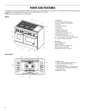
...-duty racks with handle Extendable roller rack with handle Oven Interior B C A. Temperature probe jack (not available in the left oven cavity on 48" [121.9 cm] models) E. Roller feet G. Removable lower panel L. 18" (45.7 cm) true convection oven M. 7" (17.8 cm) full color touch-anywhere LCD N. Convection fan(s) F. ... B. Broil burner (not available in the left oven cavity on some or all of your model. Oven cavity sensor A D. Electric griddle (on 48" [121.9 cm] models) A C. Dual-Fan true convection oven K. The range you have purchased may not match ...
...-duty racks with handle Extendable roller rack with handle Oven Interior B C A. Temperature probe jack (not available in the left oven cavity on 48" [121.9 cm] models) E. Roller feet G. Removable lower panel L. 18" (45.7 cm) true convection oven M. 7" (17.8 cm) full color touch-anywhere LCD N. Convection fan(s) F. ... B. Broil burner (not available in the left oven cavity on some or all of your model. Oven cavity sensor A D. Electric griddle (on 48" [121.9 cm] models) A C. Dual-Fan true convection oven K. The range you have purchased may not match ...

Use and Care
Page 10
... plastic or wooden utensils. 3. 4. Turn the griddle off during use , and does not need to catch grease and food residue. 2. Chrome Electric Griddle (on some models) B A A.
... plastic or wooden utensils. 3. 4. Turn the griddle off during use , and does not need to catch grease and food residue. 2. Chrome Electric Griddle (on some models) B A A.


