Service Manual
Page 11
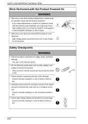
... fire. • Check wiring for edges, burrs, and other damage. They can leak, leading to a risk of electric shock or fire. • Carefully remove all toner remnants and dust from electrical parts and electrode units such as clips, staples, and screws to fall into the product. A risk of electric shock exists.
... fire. • Check wiring for edges, burrs, and other damage. They can leak, leading to a risk of electric shock or fire. • Carefully remove all toner remnants and dust from electrical parts and electrode units such as clips, staples, and screws to fall into the product. A risk of electric shock exists.
Service Manual
Page 13
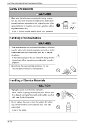
...; Make sure that were removed for safety check and maintenance have fully evaporated. Handling of Consumables WARNING • Toner and developer are noticeable, consult a physician. • Never throw the used cartridge and toner into contact with plenty of fire exists. When symptoms are not harmful substances, but care must be stimulative. A risk...
...; Make sure that were removed for safety check and maintenance have fully evaporated. Handling of Consumables WARNING • Toner and developer are noticeable, consult a physician. • Never throw the used cartridge and toner into contact with plenty of fire exists. When symptoms are not harmful substances, but care must be stimulative. A risk...

Service Manual
Page 23
If any caution label. WARNING • Do not burn used Toner Cartridge. Y WARNING • Do not burn used Waste Toner Bottle. Do not remove caution labels. Toner expelled from the fire is dangerous. S-20 A00FP0C504DA CAUTION: • You may be burned or injured if you touch any area that you are advised ... and therefore the caution cannot be read, contact our Service Office. SAFETY AND IMPORTANT WARNING ITEMS PUSH Y WARNING • Do not burn used Print Units. Toner expelled from the fire is dangerous. Toner expelled from the fire is dangerous.
If any caution label. WARNING • Do not burn used Toner Cartridge. Y WARNING • Do not burn used Waste Toner Bottle. Do not remove caution labels. Toner expelled from the fire is dangerous. S-20 A00FP0C504DA CAUTION: • You may be burned or injured if you touch any area that you are advised ... and therefore the caution cannot be read, contact our Service Office. SAFETY AND IMPORTANT WARNING ITEMS PUSH Y WARNING • Do not burn used Print Units. Toner expelled from the fire is dangerous. Toner expelled from the fire is dangerous.

Service Manual
Page 30
... creation process 7 Composition/Operation 6. Media path ...6 5. Toner supply section 15 8.1 Composition...15 8.2 Drive ...16 8.3 Operation ...17 8.3.1 Toner conveying mechanism 17 8.3.2 Toner collecting port shutter mechanism 18 8.3.3 Toner replenishing mechanism 19 8.3.4 Toner level detection 20 8.3.5 Toner near-empty condition detection 20 8.3.6 Toner empty condition detection 21 8.3.7 Toner empty condition detection control 21 8.3.8 Toner cartridge life control 21 9. Overall composition 9 6.1 Timing...
... creation process 7 Composition/Operation 6. Media path ...6 5. Toner supply section 15 8.1 Composition...15 8.2 Drive ...16 8.3 Operation ...17 8.3.1 Toner conveying mechanism 17 8.3.2 Toner collecting port shutter mechanism 18 8.3.3 Toner replenishing mechanism 19 8.3.4 Toner level detection 20 8.3.5 Toner near-empty condition detection 20 8.3.6 Toner empty condition detection 21 8.3.7 Toner empty condition detection control 21 8.3.8 Toner cartridge life control 21 9. Overall composition 9 6.1 Timing...

Service Manual
Page 31
... belt cleaning mechanism 41 13.3.7 1st transfer belt cleaning control 42 13.3.8 1st transfer belt backward rotation control 42 13.3.9 Toner collecting port shutter mechanism 43 ii Print unit section (charge corona 27 11.1 Composition ...27 11.2 Operation...28 11.2.1 Charge...Composition ...29 12.2 Operation...30 12.2.1 Developing drive control 30 12.2.2 Toner collecting port shutter mechanism 31 12.2.3 Toner flow 32 12.2.4 Developing system 33 12.2.5 Cleaning mechanism 34 12.2.6 Toner collecting port shutter mechanism 34 13. magicolor 4650EN magicolor 4650DN Outline Composition/...
... belt cleaning mechanism 41 13.3.7 1st transfer belt cleaning control 42 13.3.8 1st transfer belt backward rotation control 42 13.3.9 Toner collecting port shutter mechanism 43 ii Print unit section (charge corona 27 11.1 Composition ...27 11.2 Operation...28 11.2.1 Charge...Composition ...29 12.2 Operation...30 12.2.1 Developing drive control 30 12.2.2 Toner collecting port shutter mechanism 31 12.2.3 Toner flow 32 12.2.4 Developing system 33 12.2.5 Cleaning mechanism 34 12.2.6 Toner collecting port shutter mechanism 34 13. magicolor 4650EN magicolor 4650DN Outline Composition/...

Service Manual
Page 32
... 15.2 Drive ...50 15.3 Operation ...51 15.3.1 Toner flow at the 1st transfer section 51 15.3.2 Toner flow at the 2nd transfer section 52 15.3.3 Toner collecting port shutter mechanism at the suction transport unit........ 53 15.3.4 Toner collecting port shutter mechanism of operation Ver. 1.0 Nov....Theory of the waste toner bottle 53 15.3.5 Waste toner box locking mechanism 54 15.3.6 Waste toner box locked position detection mechanism 54 15.3.7 Waste toner box-in-position detection mechanism 55 15.3.8 Waste toner flow in the waste toner box 55 15.3.9 Waste toner near-full condition ...
... 15.2 Drive ...50 15.3 Operation ...51 15.3.1 Toner flow at the 1st transfer section 51 15.3.2 Toner flow at the 2nd transfer section 52 15.3.3 Toner collecting port shutter mechanism at the suction transport unit........ 53 15.3.4 Toner collecting port shutter mechanism of operation Ver. 1.0 Nov....Theory of the waste toner bottle 53 15.3.5 Waste toner box locking mechanism 54 15.3.6 Waste toner box locked position detection mechanism 54 15.3.7 Waste toner box-in-position detection mechanism 55 15.3.8 Waste toner flow in the waste toner box 55 15.3.9 Waste toner near-full condition ...
Service Manual
Page 33
... control 84 21.1.4 Image stabilization control execution request 85 22. Conveyance section (IDC sensor 66 18.1 Composition ...66 18.1.1 Drive ...67 18.2 Operation...67 18.2.1 Toner density detection control 67 18.2.2 IDC sensor calibration control 68 18.2.3 IDC sensor shutter mechanism 68 19. Miscellaneous ...86 iv Fusing section...75 20.1 Composition...
... control 84 21.1.4 Image stabilization control execution request 85 22. Conveyance section (IDC sensor 66 18.1 Composition ...66 18.1.1 Drive ...67 18.2 Operation...67 18.2.1 Toner density detection control 67 18.2.2 IDC sensor calibration control 68 18.2.3 IDC sensor shutter mechanism 68 19. Miscellaneous ...86 iv Fusing section...75 20.1 Composition...
Service Manual
Page 40
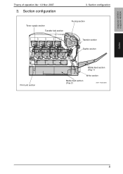
Section configuration Toner supply section Transfer belt section Fusing section Transfer section Duplex section Print unit section Media feed section (Tray 1) Write section Media feed section (Tray 2) A011T1C502AA 5 Section configuration 3. magicolor 4650EN magicolor 4650DN Outline Theory of operation Ver. 1.0 Nov. 2007 3.
Section configuration Toner supply section Transfer belt section Fusing section Transfer section Duplex section Print unit section Media feed section (Tray 1) Write section Media feed section (Tray 2) A011T1C502AA 5 Section configuration 3. magicolor 4650EN magicolor 4650DN Outline Theory of operation Ver. 1.0 Nov. 2007 3.
Service Manual
Page 42
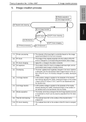
...is neutralized so that it can be properly separated from the transfer belt. • The residual toner left on the surface of the transfer belt is scraped off . • The residual toner left on the surface of the PC drum. Image creation process [9] Transfer belt cleaning [6] 1st ...The surface of the PC drum is irradiated with laser light, and an electrostatic latent image is thereby formed. • The toner, agitated and negatively charged in the toner chamber, is attracted onto the electrostatic latent image formed on the surface of operation Ver. 1.0 Nov. 2007 5. Image creation ...
...is neutralized so that it can be properly separated from the transfer belt. • The residual toner left on the surface of the transfer belt is scraped off . • The residual toner left on the surface of the PC drum. Image creation process [9] Transfer belt cleaning [6] 1st ...The surface of the PC drum is irradiated with laser light, and an electrostatic latent image is thereby formed. • The toner, agitated and negatively charged in the toner chamber, is attracted onto the electrostatic latent image formed on the surface of operation Ver. 1.0 Nov. 2007 5. Image creation ...
Service Manual
Page 49
... made for execution of an image stabilization sequence. 7.2.6 Registration correction control • In a tandem engine that has an image forming process for each color of toner, incorrect color registration tends to occur due to variations in photo conductor electrostatic characteristics, developing characteristics, and transfer characteristics (part-to-part variations, environment, durability...
... made for execution of an image stabilization sequence. 7.2.6 Registration correction control • In a tandem engine that has an image forming process for each color of toner, incorrect color registration tends to occur due to variations in photo conductor electrostatic characteristics, developing characteristics, and transfer characteristics (part-to-part variations, environment, durability...

Service Manual
Page 50
magicolor 4650EN magicolor 4650DN Theory of operation Ver. 1.0 Nov. 2007 8. Toner supply section A011T2C516AA TC detection board (CSIC) A011T2C525AA Conveyance screw A011T2C006DA Toner collecting port Agitating blade Conveyance screw A011T2C007DA Composition/Operation 15 Toner supply section 8.1 Composition 8.
magicolor 4650EN magicolor 4650DN Theory of operation Ver. 1.0 Nov. 2007 8. Toner supply section A011T2C516AA TC detection board (CSIC) A011T2C525AA Conveyance screw A011T2C006DA Toner collecting port Agitating blade Conveyance screw A011T2C007DA Composition/Operation 15 Toner supply section 8.1 Composition 8.

Service Manual
Page 51
Toner supply section 8.2 Drive Theory of operation Ver.1.0 Nov. 2007 Front view Toner supply motor/C, K (M7) Toner supply motor/Y, M (M6) 3D view 4138to2599c0 Toner supply motor/C, K (M7) Toner supply motor/Y, M (M6) Agitating blade Conveyance screw A011T2C008DA Composition/Operation 16 magicolor 4650EN magicolor 4650DN 8.
Toner supply section 8.2 Drive Theory of operation Ver.1.0 Nov. 2007 Front view Toner supply motor/C, K (M7) Toner supply motor/Y, M (M6) 3D view 4138to2599c0 Toner supply motor/C, K (M7) Toner supply motor/Y, M (M6) Agitating blade Conveyance screw A011T2C008DA Composition/Operation 16 magicolor 4650EN magicolor 4650DN 8.

Service Manual
Page 52
...the conveyance screw. Agitating blade Conveyance screw A011T2C006DA Toner collecting port Rear side Agitating blade Conveyance screw A011T2C007DA A011T2C009DA Composition/Operation 17 Toner supply section 8.3 Operation 8.3.1 Toner conveying mechanism • The toner supply motor is turned either forward or backward to...the conveyance screw. • The agitating blade provided in the toner cartridge agitates and conveys toner to the conveyance screw. • The toner conveyed by the agitating blade is conveyed to the toner collecting port sitting on the front side of operation Ver. ...
...the conveyance screw. Agitating blade Conveyance screw A011T2C006DA Toner collecting port Rear side Agitating blade Conveyance screw A011T2C007DA A011T2C009DA Composition/Operation 17 Toner supply section 8.3 Operation 8.3.1 Toner conveying mechanism • The toner supply motor is turned either forward or backward to...the conveyance screw. • The agitating blade provided in the toner cartridge agitates and conveys toner to the conveyance screw. • The toner conveyed by the agitating blade is conveyed to the toner collecting port sitting on the front side of operation Ver. ...
Service Manual
Page 53
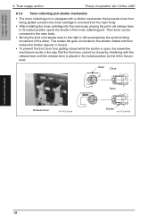
...8226; Moving the print unit release lever to the left in the locked position (to the right or left accompanies the synchronizing movement of the toner collecting port. This makes the gear connected to the shutter rotated and then makes the shutter opened or closed. • To prevent the ...front door from the main body. • After installing the toner cartridge into the main body, placing the print unit release lever in its locked position opens the shutter of the slider. magicolor 4650EN magicolor 4650DN...
...8226; Moving the print unit release lever to the left in the locked position (to the right or left accompanies the synchronizing movement of the toner collecting port. This makes the gear connected to the shutter rotated and then makes the shutter opened or closed. • To prevent the ...front door from the main body. • After installing the toner cartridge into the main body, placing the print unit release lever in its locked position opens the shutter of the slider. magicolor 4650EN magicolor 4650DN...

Service Manual
Page 54
... clutch turns. This is then supplied from the toner cartridge to the print unit as viewed from the toner cartridge while the print unit remains stationary, toner stagnates at the print unit. Toner is because of operation Ver. 1.0 Nov. 2007 8. Toner supply section 8.3.3 Toner replenishing mechanism • The toner supply motor is turned either forward or backward...
... clutch turns. This is then supplied from the toner cartridge to the print unit as viewed from the toner cartridge while the print unit remains stationary, toner stagnates at the print unit. Toner is because of operation Ver. 1.0 Nov. 2007 8. Toner supply section 8.3.3 Toner replenishing mechanism • The toner supply motor is turned either forward or backward...

Service Manual
Page 55
... 8,000 printed Approx. 3,200 sheets * for determining whether there is a toner near -empty condition when the toner level remaining in the toner cartridge becomes approx. 40 percent. Composition/Operation 20 Toner supply section Theory of operation Ver.1.0 Nov. 2007 8.3.4 Toner level detection • The toner level is determined by the accumulated time of rotation of the...
... 8,000 printed Approx. 3,200 sheets * for determining whether there is a toner near -empty condition when the toner level remaining in the toner cartridge becomes approx. 40 percent. Composition/Operation 20 Toner supply section Theory of operation Ver.1.0 Nov. 2007 8.3.4 Toner level detection • The toner level is determined by the accumulated time of rotation of the...
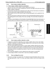
Service Manual
Page 56
... below a predetermined value and if the following event is detected a predetermined number of consecutive times: the output value of the toner level sensor remains a predetermined value or lower for more than a predetermined period of time. • The consecutive detection count is... retained even when power is turned OFF. • A toner empty condition is reset when a new toner cartridge is detected. 8.3.8 Toner cartridge life control • Each toner cartridge is provided with a TC detection board that cleans the window in the main body. &#...
... below a predetermined value and if the following event is detected a predetermined number of consecutive times: the output value of the toner level sensor remains a predetermined value or lower for more than a predetermined period of time. • The consecutive detection count is... retained even when power is turned OFF. • A toner empty condition is reset when a new toner cartridge is detected. 8.3.8 Toner cartridge life control • Each toner cartridge is provided with a TC detection board that cleans the window in the main body. &#...

Service Manual
Page 57
9. Print unit section (overall composition) Theory of operation Ver.1.0 Nov. 2007 9. Print unit section (overall composition) 9.1 Composition magicolor 4650EN magicolor 4650DN Composition/Operation PC motor A011T2C517AA PU detection board (CSIC) A011T2C526AA Developing motor Replenishing screw Agitating screw Supply roller Developing roller A011T2C013DA Photo conductor Cleaning blade Charge corona A011T2C014DA Toner collecting screw 22
9. Print unit section (overall composition) Theory of operation Ver.1.0 Nov. 2007 9. Print unit section (overall composition) 9.1 Composition magicolor 4650EN magicolor 4650DN Composition/Operation PC motor A011T2C517AA PU detection board (CSIC) A011T2C526AA Developing motor Replenishing screw Agitating screw Supply roller Developing roller A011T2C013DA Photo conductor Cleaning blade Charge corona A011T2C014DA Toner collecting screw 22

Service Manual
Page 58
... cartridge life is determined. • When the photo conductor driving time reaches its life, a life end warning message appears. magicolor 4650EN magicolor 4650DN Theory of a toner cartridge placement, a new PU, a print unit life. • The main body attempts to perform a detection sequence when the front door is closed. • When a cartridge...
... cartridge life is determined. • When the photo conductor driving time reaches its life, a life end warning message appears. magicolor 4650EN magicolor 4650DN Theory of a toner cartridge placement, a new PU, a print unit life. • The main body attempts to perform a detection sequence when the front door is closed. • When a cartridge...

Service Manual
Page 60
... for the drive mechanism independently of the developing system to suppress incorrect color registration and uneven pitch. • To stop the drive for the color toner cartridges in the monochrome mode, different motors are used to drive the color photo conductors and black photo conductor. • The color PC drum motor...
... for the drive mechanism independently of the developing system to suppress incorrect color registration and uneven pitch. • To stop the drive for the color toner cartridges in the monochrome mode, different motors are used to drive the color photo conductors and black photo conductor. • The color PC drum motor...

