
Owner's Manual (English)
Page 6
... SAFETY INSTRUCTIONS 2 INTRODUCTION 6 Feature of this TV 6 PREPARATION Accessories 7 Front Panel Information 8 Back Panel Information 10 Back Cover for Wire Arrangement 12 Attaching the TV to a Wall 14 Stand Installation 15 VESA Wall Mounting 16 Desktop Pedestal Installation 16 Antenna or Cable Connection 17 EXTERNAL EQUIPMENT SETUP HD Receiver Setup 18 DVD Setup 21 VCR Setup 23 Other A/V Source Setup 25 PC Setup 26 AV Out Setup & Digital Audio Output 29 WATCHING TV / CHANNEL CONTROL Remote Control Key Functions 30 Turning On TV 32 Channel Selection 32 Volume Adjustment...
... SAFETY INSTRUCTIONS 2 INTRODUCTION 6 Feature of this TV 6 PREPARATION Accessories 7 Front Panel Information 8 Back Panel Information 10 Back Cover for Wire Arrangement 12 Attaching the TV to a Wall 14 Stand Installation 15 VESA Wall Mounting 16 Desktop Pedestal Installation 16 Antenna or Cable Connection 17 EXTERNAL EQUIPMENT SETUP HD Receiver Setup 18 DVD Setup 21 VCR Setup 23 Other A/V Source Setup 25 PC Setup 26 AV Out Setup & Digital Audio Output 29 WATCHING TV / CHANNEL CONTROL Remote Control Key Functions 30 Turning On TV 32 Channel Selection 32 Volume Adjustment...

Owner's Manual (English)
Page 8
... all models. Wide angle range of vision Your flat panel plasma screen offers an exceptionally broad viewing angle of as tiny red, green, or blue spots. Thus a few cell defects are comprised of locations where conventional TVs do not fit. The fan noise doesn't have no adverse effect on the screen. The fluorescent lamp used in a display that are the same types used in other Plasma TV...
... all models. Wide angle range of vision Your flat panel plasma screen offers an exceptionally broad viewing angle of as tiny red, green, or blue spots. Thus a few cell defects are comprised of locations where conventional TVs do not fit. The fan noise doesn't have no adverse effect on the screen. The fluorescent lamp used in a display that are the same types used in other Plasma TV...

Owner's Manual (English)
Page 10
... turned on, the indicator blinks green and then illuminates green before the picture is included with your product, use it). Front Panel Controls Plasma TV Model PREPARATION Remote Control Sensor Power/Standby Indicator Illuminates red in standby mode. INPUT MENU ENTER VOL CH INPUT MENU ENTER VOL CH POWER Button INPUT Button MENU Button ENTER Button VOLUME (F,G)Buttons CHANNEL (E,D)Buttons 8 And then wipe the product with a cloth (If a polishing cloth is displayed. PREPARATION FRONT PANEL INFORMATION I NOTE: If your product has a protection tape attached, remove...
... turned on, the indicator blinks green and then illuminates green before the picture is included with your product, use it). Front Panel Controls Plasma TV Model PREPARATION Remote Control Sensor Power/Standby Indicator Illuminates red in standby mode. INPUT MENU ENTER VOL CH INPUT MENU ENTER VOL CH POWER Button INPUT Button MENU Button ENTER Button VOLUME (F,G)Buttons CHANNEL (E,D)Buttons 8 And then wipe the product with a cloth (If a polishing cloth is displayed. PREPARATION FRONT PANEL INFORMATION I NOTE: If your product has a protection tape attached, remove...
Owner's Manual (English)
Page 18
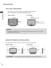
..., refer to the VESA Wall Mounting Instruction Guide. ( ) ( ) DESKTOP PEDESTAL INSTALLATION For proper ventilation, allow a clearance of 4inches on the wall mount used. Plasma TV Model LCD TV Model 4 inches 4 inches 4 inches 4 inches 4 inches 4 inches 4 inches 4 inches CAUTION G Ensure adequate ventilation by following the clearance recommendations. 16 PREPARATION PREPARATION VESA WALL MOUNTING This product accepts a VESA-compliant mounting interface pad. (optional) There 4 threaded holes are available for attaching the bracket. NOTE G Screw length needed depends on all...
..., refer to the VESA Wall Mounting Instruction Guide. ( ) ( ) DESKTOP PEDESTAL INSTALLATION For proper ventilation, allow a clearance of 4inches on the wall mount used. Plasma TV Model LCD TV Model 4 inches 4 inches 4 inches 4 inches 4 inches 4 inches 4 inches 4 inches CAUTION G Ensure adequate ventilation by following the clearance recommendations. 16 PREPARATION PREPARATION VESA WALL MOUNTING This product accepts a VESA-compliant mounting interface pad. (optional) There 4 threaded holes are available for attaching the bracket. NOTE G Screw length needed depends on all...
Owner's Manual (English)
Page 20
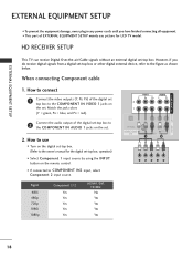
...the set. 2. When connecting Component cable 1. VIDEO AUDIO 2 Connect the audio output of EXTERNAL EQUIPMENT SETUP mainly use I Turn on the remote control. How to use picture for the digital set-top box. I This part of the digital set-top box to the COMPONENT IN AUDIO 1 jacks on the set. However, if you have finished connecting all equipment. operation) I Select Component 1 input source by using the INPUT button on the digital set-top box. (Refer to the owner's manual for LCD TV model. I If connected to COMPONENT IN2 input, select Component 2 input source. Signal...
...the set. 2. When connecting Component cable 1. VIDEO AUDIO 2 Connect the audio output of EXTERNAL EQUIPMENT SETUP mainly use I Turn on the remote control. How to use picture for the digital set-top box. I This part of the digital set-top box to the COMPONENT IN AUDIO 1 jacks on the set. However, if you have finished connecting all equipment. operation) I Select Component 1 input source by using the INPUT button on the digital set-top box. (Refer to the owner's manual for LCD TV model. I If connected to COMPONENT IN2 input, select Component 2 input source. Signal...
Owner's Manual (English)
Page 21
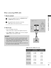
... connected, the TV will be automatically set the output resolution appropriately. HDMI supports both audio and video. 2. If the device supports this Auto HDMI function, the player output resolution will tell a connected device what resolution it supports and the resolution it prefers. G If the device does not support Auto HDMI, you need to set to 720p. SERVICE RGB IN (PC) ANTENNA/ CABLE IN HDMI IN 2 1 HDMI/DVI IN AUDIO IN REMOTE (RGB/DVI) CONTROL IN RS-232C IN (CONTROL & SERVICE) 1 HDMI-DTV OUTPUT HDMI1/DVI-DTV, HDMI2-DTV mode Resolution Horizontal Vertical...
... connected, the TV will be automatically set the output resolution appropriately. HDMI supports both audio and video. 2. If the device supports this Auto HDMI function, the player output resolution will tell a connected device what resolution it supports and the resolution it prefers. G If the device does not support Auto HDMI, you need to set to 720p. SERVICE RGB IN (PC) ANTENNA/ CABLE IN HDMI IN 2 1 HDMI/DVI IN AUDIO IN REMOTE (RGB/DVI) CONTROL IN RS-232C IN (CONTROL & SERVICE) 1 HDMI-DTV OUTPUT HDMI1/DVI-DTV, HDMI2-DTV mode Resolution Horizontal Vertical...
Owner's Manual (English)
Page 22
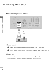
... audio output of the digital set-top box to the AUDIO IN (RGB/DVI) jack on the set -top box.) I Select HDMI1/DVI input source by using the INPUT button on the digital set-top box. (Refer to the owner's manual for the digital set . 2. COMPONENT IN AV OUT AV IN 1 EXTERNAL EQUIPMENT SETUP EXTERNAL EQUIPMENT SETUP When connecting HDMI to use I Turn on the remote control. 20 How to DVI cable SERVICE RGB IN (PC) VIDEO AUDIO ANTENNA/ CABLE IN HDMI IN 2 1 HDMI/DVI IN AUDIO IN REMOTE (RGB/DVI) CONTROL IN RS-232C IN (CONTROL & SERVICE) OPTICAL DIGITAL AUDIO...
... audio output of the digital set-top box to the AUDIO IN (RGB/DVI) jack on the set -top box.) I Select HDMI1/DVI input source by using the INPUT button on the digital set-top box. (Refer to the owner's manual for the digital set . 2. COMPONENT IN AV OUT AV IN 1 EXTERNAL EQUIPMENT SETUP EXTERNAL EQUIPMENT SETUP When connecting HDMI to use I Turn on the remote control. 20 How to DVI cable SERVICE RGB IN (PC) VIDEO AUDIO ANTENNA/ CABLE IN HDMI IN 2 1 HDMI/DVI IN AUDIO IN REMOTE (RGB/DVI) CONTROL IN RS-232C IN (CONTROL & SERVICE) OPTICAL DIGITAL AUDIO...

Owner's Manual (English)
Page 23
... 1 DVD SETUP When connecting Component cable 1. I If connected to COMPONENT IN 2 input, select Component 2 input source. I Select Component 1 input source by using the INPUT button on the remote control. Component ports on the TV Y PB PR Video output ports on the set . 2. How to use I Refer to the COMPONENT IN AUDIO1 jacks on the DVD player, insert a DVD. How to connect 1 Connect the video outputs (Y, PB, PR) of the DVD to the DVD player's manual for operating instructions. I Turn on the set . VIDEO AUDIO OPTICAL DIGITAL AUDIO OUT (MONO) S-VIDEO VIDEO AUDIO...
... 1 DVD SETUP When connecting Component cable 1. I If connected to COMPONENT IN 2 input, select Component 2 input source. I Select Component 1 input source by using the INPUT button on the remote control. Component ports on the TV Y PB PR Video output ports on the set . 2. How to use I Refer to the COMPONENT IN AUDIO1 jacks on the DVD player, insert a DVD. How to connect 1 Connect the video outputs (Y, PB, PR) of the DVD to the DVD player's manual for operating instructions. I Turn on the set . VIDEO AUDIO OPTICAL DIGITAL AUDIO OUT (MONO) S-VIDEO VIDEO AUDIO...

Owner's Manual (English)
Page 24
...the DVD to the DVD player's manual for operating instructions. When connecting HDMI cable 1. I Select A V 1 input source by using the INPUT button on the set the output resolution appropriately. S-VIDEO AUDIO L R VIDEO 1 AUDIO 2 OPTICAL DIGITAL AUDIO OUT S-VIDEO VIDEO (MONO) AUDIO SERVICE RGB IN (PC) ANTENNA/ CABLE IN HDMI IN 2 1 HDMI/DVI IN AUDIO IN REMOT (RGB/DVI) CONTROL RS-232C IN (CONTROL & SERVICE ! I Refer to the DVD player's manual for operating instructions. NOTE G When connected, the TV will be automatically set . 2. If the device supports this Auto...
...the DVD to the DVD player's manual for operating instructions. When connecting HDMI cable 1. I Select A V 1 input source by using the INPUT button on the set the output resolution appropriately. S-VIDEO AUDIO L R VIDEO 1 AUDIO 2 OPTICAL DIGITAL AUDIO OUT S-VIDEO VIDEO (MONO) AUDIO SERVICE RGB IN (PC) ANTENNA/ CABLE IN HDMI IN 2 1 HDMI/DVI IN AUDIO IN REMOT (RGB/DVI) CONTROL RS-232C IN (CONTROL & SERVICE ! I Refer to the DVD player's manual for operating instructions. NOTE G When connected, the TV will be automatically set . 2. If the device supports this Auto...

Owner's Manual (English)
Page 25
... press PLAY on the VCR. (Refer to the VCR owner's manual.) ( ) AUDIO 23 This phenomenon is used; If the 4:3 picture format is common to all manufactures and in the Option menu to avoid having a fixed image remain on the screen for a long period of time. When connecting with an antenna 1 S-VIDEO VIDEO L R ANT OUT OUTPUT SWITCH ANT IN Wall Jack 2 RGB IN (PC) ANTENNA/ CABLE IN HDMI IN 2 1 HDMI/DVI IN AUDIO IN REMOTE (RGB/DVI) CONTROL IN...
... press PLAY on the VCR. (Refer to the VCR owner's manual.) ( ) AUDIO 23 This phenomenon is used; If the 4:3 picture format is common to all manufactures and in the Option menu to avoid having a fixed image remain on the screen for a long period of time. When connecting with an antenna 1 S-VIDEO VIDEO L R ANT OUT OUTPUT SWITCH ANT IN Wall Jack 2 RGB IN (PC) ANTENNA/ CABLE IN HDMI IN 2 1 HDMI/DVI IN AUDIO IN REMOTE (RGB/DVI) CONTROL IN...

Owner's Manual (English)
Page 26
... cable) input. Match the jack colors (Video = yellow, Audio Left = white, and Audio Right = red) 2. How to use I Insert a video tape into the VCR and press PLAY on the remote control. I If connected to the VCR owner's manual.) I Select A V 1 input source by using the INPUT button on the VCR. (Refer to AV IN2, select A V 2 input source. How to connect 1 Connect the S-VIDEO output of the VCR to the S -VIDEO input on the set . 1. NOTE G The picture quality is improved: compared to connect 1 Connect...
... cable) input. Match the jack colors (Video = yellow, Audio Left = white, and Audio Right = red) 2. How to use I Insert a video tape into the VCR and press PLAY on the remote control. I If connected to the VCR owner's manual.) I Select A V 1 input source by using the INPUT button on the VCR. (Refer to AV IN2, select A V 2 input source. How to connect 1 Connect the S-VIDEO output of the VCR to the S -VIDEO input on the set . 1. NOTE G The picture quality is improved: compared to connect 1 Connect...

Owner's Manual (English)
Page 28
... 2 1 HDMI/DVI IN AUDIO IN REMOTE (RGB/DVI) CONTROL RS-232C IN (CONTROL & SERVICE 2. How to connect 1 Connect the DVI output of the PC to use I Select RGB-PC input source by using the INPUT button on the remote control. 1 2 26 DVI-PC OUTPUT AUDIO EXTERNAL EQUIPMENT SETUP EXTERNAL EQUIPMENT SETUP PC SETUP This TV provides Plug and Play capability, meaning that the PC adjusts automatically to DVI cable 1. I Turn on the set . How to the RGB IN (P C) jack on the PC and the TV. Connect the PC audio output...
... 2 1 HDMI/DVI IN AUDIO IN REMOTE (RGB/DVI) CONTROL RS-232C IN (CONTROL & SERVICE 2. How to connect 1 Connect the DVI output of the PC to use I Select RGB-PC input source by using the INPUT button on the remote control. 1 2 26 DVI-PC OUTPUT AUDIO EXTERNAL EQUIPMENT SETUP EXTERNAL EQUIPMENT SETUP PC SETUP This TV provides Plug and Play capability, meaning that the PC adjusts automatically to DVI cable 1. I Turn on the set . How to the RGB IN (P C) jack on the PC and the TV. Connect the PC audio output...

Owner's Manual (English)
Page 30
... see the best picture appearance. In HDMI/DVI-PC mode, Size is not available. Initializing (Reset to original factory values) To initialize the adjusted values 1 Press the ADJUST button and then use D or E button to select Reset. 2 Press the ENTER button and then use D E F G button to PC output and select HDMI/DVI input, this function is used. EXTERNAL EQUIPMENT SETUP EXTERNAL EQUIPMENT SETUP Screen Setup for screen Resolution, Position, Size, and Phase 1 Press the ADJUST button and then use D or E button to select Resolution, Position, Size, or...
... see the best picture appearance. In HDMI/DVI-PC mode, Size is not available. Initializing (Reset to original factory values) To initialize the adjusted values 1 Press the ADJUST button and then use D or E button to select Reset. 2 Press the ENTER button and then use D E F G button to PC output and select HDMI/DVI input, this function is used. EXTERNAL EQUIPMENT SETUP EXTERNAL EQUIPMENT SETUP Screen Setup for screen Resolution, Position, Size, and Phase 1 Press the ADJUST button and then use D or E button to select Resolution, Position, Size, or...

Owner's Manual (English)
Page 31
...'s input settings. ! ICAL L AUDIO UT S-VIDEO VIDEO (MONO) AUDIO 1 VIDEO L R S-VIDEO DIGITAL AUDIO OUTPUT Send the TV's audio to hook up the second TV or monitor. 1. NOTE G When connecting with external audio equipments, such as amplifiers or speakers, please turn the TV speakers off. (G p.57) CAUTION G Do not look into the optical output port. NOTE G Component1-2, RGB-PC, HDMI1/DVI, HDMI2, DTV input sources cannot be used for operation. Off" in the AUDIO menu. (G p.57). See the Operating Manual of the optical cable to the digital audio (optical) input...
...'s input settings. ! ICAL L AUDIO UT S-VIDEO VIDEO (MONO) AUDIO 1 VIDEO L R S-VIDEO DIGITAL AUDIO OUTPUT Send the TV's audio to hook up the second TV or monitor. 1. NOTE G When connecting with external audio equipments, such as amplifiers or speakers, please turn the TV speakers off. (G p.57) CAUTION G Do not look into the optical output port. NOTE G Component1-2, RGB-PC, HDMI1/DVI, HDMI2, DTV input sources cannot be used for operation. Off" in the AUDIO menu. (G p.57). See the Operating Manual of the optical cable to the digital audio (optical) input...
Owner's Manual (English)
Page 34
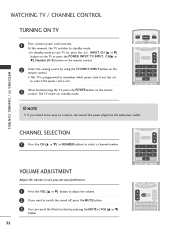
... the Mute function by using the TV, press the POWER button on the remote control. TV INPUT POWER DVD TV MODE INPUT VCR EXIT TIMER RATIO SIMPLINK VOL MUTE FAV CH 1 2 3 4 5 6 7 8 9 0 BACK PICTURE SOUND SAP CC WATCHING TV / CHANNEL CONTROL ! At this moment, the TV switches to select a channel number. The TV reverts to turn TV on, press the , INPUT, CH (D or E) button on the TV or press the POWER, INPUT, TV INPUT, CH(D or E), Number (0~9) button on the remote control. 2 Select the viewing source by pressing the MUTE...
... the Mute function by using the TV, press the POWER button on the remote control. TV INPUT POWER DVD TV MODE INPUT VCR EXIT TIMER RATIO SIMPLINK VOL MUTE FAV CH 1 2 3 4 5 6 7 8 9 0 BACK PICTURE SOUND SAP CC WATCHING TV / CHANNEL CONTROL ! At this moment, the TV switches to select a channel number. The TV reverts to turn TV on, press the , INPUT, CH (D or E) button on the TV or press the POWER, INPUT, TV INPUT, CH(D or E), Number (0~9) button on the remote control. 2 Select the viewing source by pressing the MUTE...
Owner's Manual (English)
Page 35
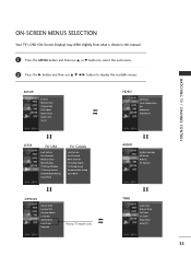
...EZ Scan Manual Scan Channel Edit DTV Signal Input Source Input Label Set ID VIDEO EZ Picture Color Temperature XD Advanced Video Reset WATCHING TV / CHANNEL CONTROL LOCK For USA Lock System Set Password Block Channel Movie Rating TV Rating-Children TV Rating-General Downloadable Rating Input Block For Canada Lock System Set Password Block Channel TV Rating-English TV Rating-French Downloadable Rating Input Block OPTION Aspect Ratio Caption/Text Caption Option Language ISM Method Low Power SimpLink Plasma TV model only AUDIO Audio Language EZ Sound Balance TV Speaker TIME Auto Clock...
...EZ Scan Manual Scan Channel Edit DTV Signal Input Source Input Label Set ID VIDEO EZ Picture Color Temperature XD Advanced Video Reset WATCHING TV / CHANNEL CONTROL LOCK For USA Lock System Set Password Block Channel Movie Rating TV Rating-Children TV Rating-General Downloadable Rating Input Block For Canada Lock System Set Password Block Channel TV Rating-English TV Rating-French Downloadable Rating Input Block OPTION Aspect Ratio Caption/Text Caption Option Language ISM Method Low Power SimpLink Plasma TV model only AUDIO Audio Language EZ Sound Balance TV Speaker TIME Auto Clock...

Owner's Manual (English)
Page 36
... Antenna/Cable connection changes. Allow EZ Scan to stop the current scan and start DIGITAL ANTENNA channel scan. A password is required to gain access to EZ Scan menu if the Lock System is turned on the channel list. MENU BRIGHT + ENTER EXIT TIMER RATIO SIMPLINK EZ Scan Manual Scan Channel Edit DTV Signal Input Source Input Label Set ID EZ Scan Manual Scan Channel Edit DTV Signal Input Source Input Label Set ID 1 G Selection ( G or ) leads you to the EZ scan screen. TV INPUT POWER TV AUDIO DVD MODE CABLE INPUT VCR STB BRIGHT - Processing EZ scan... TV Ch.20 0 channel...
... Antenna/Cable connection changes. Allow EZ Scan to stop the current scan and start DIGITAL ANTENNA channel scan. A password is required to gain access to EZ Scan menu if the Lock System is turned on the channel list. MENU BRIGHT + ENTER EXIT TIMER RATIO SIMPLINK EZ Scan Manual Scan Channel Edit DTV Signal Input Source Input Label Set ID EZ Scan Manual Scan Channel Edit DTV Signal Input Source Input Label Set ID 1 G Selection ( G or ) leads you to the EZ scan screen. TV INPUT POWER TV AUDIO DVD MODE CABLE INPUT VCR STB BRIGHT - Processing EZ scan... TV Ch.20 0 channel...
Owner's Manual (English)
Page 71
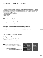
... block specific channels, ratings, and external viewing sources. It is set up blocking schemes to be blocked. 2. Specify a password 3. Ratings for Television programs including made-for a time period. For USA For Canada Lock System Set Password Block Channel Movie Rating TV Rating-Children TV Rating-General Downloadable Rating Input Block Lock System Set Password Block Channel TV Rating-English TV Rating-French Downloadable Rating Input Block PARENTAL CONTROL / RATING 69 The default setting is used to allow all program viewing for -TV movies : I TV...
... block specific channels, ratings, and external viewing sources. It is set up blocking schemes to be blocked. 2. Specify a password 3. Ratings for Television programs including made-for a time period. For USA For Canada Lock System Set Password Block Channel Movie Rating TV Rating-Children TV Rating-General Downloadable Rating Input Block Lock System Set Password Block Channel TV Rating-English TV Rating-French Downloadable Rating Input Block PARENTAL CONTROL / RATING 69 The default setting is used to allow all program viewing for -TV movies : I TV...
Owner's Manual (English)
Page 82
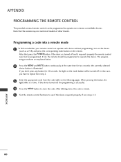
... remote should be programmed. After blinking twice, this code is illuminated. If the device turned off and it responds properly the remote control need not be programmed to operate most remote-controllable devices. ming procedures are explained below. 2 Press the MENU and MUTE button continuously at a time. APPENDIX 80 When pressing the button, the light blinks at the same time for 20 seconds, the light on the mode button will be programmed...
... remote should be programmed. After blinking twice, this code is illuminated. If the device turned off and it responds properly the remote control need not be programmed to operate most remote-controllable devices. ming procedures are explained below. 2 Press the MENU and MUTE button continuously at a time. APPENDIX 80 When pressing the button, the light blinks at the same time for 20 seconds, the light on the mode button will be programmed...

Owner's Manual (English)
Page 90
... control the set.(j, k, m or x) [Command 2] : Second command to choose desired TV ID number in Setup menu. At this model, TV will not send the status during the standby mode. * Data Format [Command2][ ][Set ID][ ][OK][Data][x] [Command 2] : Use as command. * In this format when receiving abnormal data from non-viable functions or communication errors. Bass k g 0 ~ 64 16. When selecting Set ID '0', every connected the TV is 1~ 99. mat when receiving...
... control the set.(j, k, m or x) [Command 2] : Second command to choose desired TV ID number in Setup menu. At this model, TV will not send the status during the standby mode. * Data Format [Command2][ ][Set ID][ ][OK][Data][x] [Command 2] : Use as command. * In this format when receiving abnormal data from non-viable functions or communication errors. Bass k g 0 ~ 64 16. When selecting Set ID '0', every connected the TV is 1~ 99. mat when receiving...


