
Embedded Integration Kit (EIK) - User Guide
Page 9
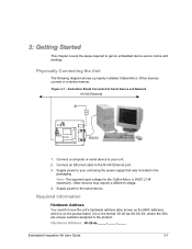
...Required Information Hardware Address You need to the serial device. Other devices connect in the packaging. Note: The required input voltage for the CoBox-Micro is in the format: 00-20-4a-XX-XX-XX, where the XXs are unique numbers assigned to your unit using the power .... 3. Other devices may require a different voltage. 4. It is 5VDC (3 W maximum). Physically Connecting the Unit The following diagram shows a properly installed CoBox-Micro. Hardware Address: 00-20-4a Embedded Integration Kit User Guide 3-1 Figure 3-1 - Connect a computer or serial device to the product.
...Required Information Hardware Address You need to the serial device. Other devices connect in the packaging. Note: The required input voltage for the CoBox-Micro is in the format: 00-20-4a-XX-XX-XX, where the XXs are unique numbers assigned to your unit using the power .... 3. Other devices may require a different voltage. 4. It is 5VDC (3 W maximum). Physically Connecting the Unit The following diagram shows a properly installed CoBox-Micro. Hardware Address: 00-20-4a Embedded Integration Kit User Guide 3-1 Figure 3-1 - Connect a computer or serial device to the product.
Embedded Integration Kit (EIK) - User Guide
Page 33
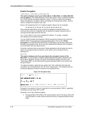
...UDP. Once you have obtained the firmware with an identical encryption string are able to change the encryption key code. Currently, Lantronix does not provide a Telnet application that will display the Change Keys option, which completely disables the 128-bit Twofish encryption algorithm...the encryption option will allow the user to make an encrypted socket connection to the port selected for Configuration Enable Encryption CoBox-Micro, CoBox-Mini, CoBox-Mini100 This option displays only if your device server. Encryption Keys Encryption only applies to the device server serial port...
...UDP. Once you have obtained the firmware with an identical encryption string are able to change the encryption key code. Currently, Lantronix does not provide a Telnet application that will display the Change Keys option, which completely disables the 128-bit Twofish encryption algorithm...the encryption option will allow the user to make an encrypted socket connection to the port selected for Configuration Enable Encryption CoBox-Micro, CoBox-Mini, CoBox-Mini100 This option displays only if your device server. Encryption Keys Encryption only applies to the device server serial port...

Embedded Integration Kit (EIK) - User Guide
Page 37
.... Via TFTP To download new firmware from the Lantronix web site (www.lantronix.com) or by using anonymous FTP (ftp.lantronix.com). The CoBox-Mini100 and the Micro100 use the same version of firmware. Check the Lantronix web site for the unit from a computer: ...via another unit, or via TFTP or DeviceInstaller. 5: Updating Firmware The CoBox-Micro and CoBox-Mini products use slightly different versions with similar functionality. Firmware Examples Folder Name CoBox-micro CoBox-mini CoBox-mini100 CoBox-micro100 ROM File Ltx45.rom Ltx45.rom Ltx45.rom M100e55.rom COB Cbxw300....
.... Via TFTP To download new firmware from the Lantronix web site (www.lantronix.com) or by using anonymous FTP (ftp.lantronix.com). The CoBox-Mini100 and the Micro100 use the same version of firmware. Check the Lantronix web site for the unit from a computer: ...via another unit, or via TFTP or DeviceInstaller. 5: Updating Firmware The CoBox-Micro and CoBox-Mini products use slightly different versions with similar functionality. Firmware Examples Folder Name CoBox-micro CoBox-mini CoBox-mini100 CoBox-micro100 ROM File Ltx45.rom Ltx45.rom Ltx45.rom M100e55.rom COB Cbxw300....

Embedded Integration Kit (EIK) - Integration Guide
Page 3
... Introduction 1-1 Embedded Integration Kits 1-1 About this Guide 1-1 Purpose and Audience 1-1 Chapter Summary 1-1 Additional Documentation 1-2 2: CoBox-Micro 2-1 Layout and Dimensions 2-1 Connectors 2-2 Ethernet Interface 2-3 Status LEDs 2-3 Test Bed 2-4 Board Layout 2-5 Test Bed Connectors... Test Bed 3-4 Board Layout 3-5 Test Bed Connectors 3-6 Technical Specifications 3-7 Product Information Label 3-7 4: CoBox-Mini 4-1 Layout and Dimensions 4-1 Connectors 4-2 LED Control Signals 4-3 Test Bed 4-3 Board Layout 4-4 Test Bed Connectors 4-4 ...
... Introduction 1-1 Embedded Integration Kits 1-1 About this Guide 1-1 Purpose and Audience 1-1 Chapter Summary 1-1 Additional Documentation 1-2 2: CoBox-Micro 2-1 Layout and Dimensions 2-1 Connectors 2-2 Ethernet Interface 2-3 Status LEDs 2-3 Test Bed 2-4 Board Layout 2-5 Test Bed Connectors... Test Bed 3-4 Board Layout 3-5 Test Bed Connectors 3-6 Technical Specifications 3-7 Product Information Label 3-7 4: CoBox-Mini 4-1 Layout and Dimensions 4-1 Connectors 4-2 LED Control Signals 4-3 Test Bed 4-3 Board Layout 4-4 Test Bed Connectors 4-4 ...

Embedded Integration Kit (EIK) - Integration Guide
Page 5
...-Layer Board Strategy 6-5 List of Figures Figure 2-1. Carrier Board 2-5 Figure 2-7. Micro100 Test Bed Connectors 3-6 Table 3-4. CoBox-Mini100 Connectors 5-2 Figure 5-3. CoBox-Micro Connector Pinouts 2-2 Table 2-2. CoBox-Micro Technical Specifications 2-7 Table 3-1. CoBox-Mini LED Signals 4-3 Table 4-3. Micro100 Results 6-3 Table 6-3. CoBox-Mini100 LED Signals 5-3 Table 5-3. CoBox-Micro, Top View 2-1 Figure 2-2 - RJ45 Ethernet Connector 3-3 Figure 3-5. Carrier Board 3-5 Figure 3-8. List of Tables Table 2-1. Pin...
...-Layer Board Strategy 6-5 List of Figures Figure 2-1. Carrier Board 2-5 Figure 2-7. Micro100 Test Bed Connectors 3-6 Table 3-4. CoBox-Mini100 Connectors 5-2 Figure 5-3. CoBox-Micro Connector Pinouts 2-2 Table 2-2. CoBox-Micro Technical Specifications 2-7 Table 3-1. CoBox-Mini LED Signals 4-3 Table 4-3. Micro100 Results 6-3 Table 6-3. CoBox-Mini100 LED Signals 5-3 Table 5-3. CoBox-Micro, Top View 2-1 Figure 2-2 - RJ45 Ethernet Connector 3-3 Figure 3-5. Carrier Board 3-5 Figure 3-8. List of Tables Table 2-1. Pin...

Embedded Integration Kit (EIK) - Integration Guide
Page 6
... kit. 3:2: Micro100 Describes and provides information about the Micro100 and its integration kit. 4: Cobox-Mini Describes and provides information about the CoBox Mini and its integration kit. 1: Introduction Embedded Integration Kits The Lantronix Embedded Integration Kits (Mini-Kit, Mini100-Kit, Micro-Kit, Micro100Kit) provide a simple method of those products. The intended audience is the...
... kit. 3:2: Micro100 Describes and provides information about the Micro100 and its integration kit. 4: Cobox-Mini Describes and provides information about the CoBox Mini and its integration kit. 1: Introduction Embedded Integration Kits The Lantronix Embedded Integration Kits (Mini-Kit, Mini100-Kit, Micro-Kit, Micro100Kit) provide a simple method of those products. The intended audience is the...

Embedded Integration Kit (EIK) - Integration Guide
Page 7
...the test setup and resultant emission profiles of the CoBox-Mini, CoBox-Mini100, CoBox-Micro, and Micro100. Additional Documentation The following guides are available on the product CD and the Lantronix Web site (www.lantronix.com) Embedded Integration Kit User Guide Provides information ... Integration Kit Integration Guide Com Port Redirector User Guide Provides information on using the Windows-based utility to configure Lantronix embedded device servers. Provides general guidelines to configure, use, and update the firmware. Introduction 5: CoBoxMini100 6: Integration Guidelines ...
...the test setup and resultant emission profiles of the CoBox-Mini, CoBox-Mini100, CoBox-Micro, and Micro100. Additional Documentation The following guides are available on the product CD and the Lantronix Web site (www.lantronix.com) Embedded Integration Kit User Guide Provides information ... Integration Kit Integration Guide Com Port Redirector User Guide Provides information on using the Windows-based utility to configure Lantronix embedded device servers. Provides general guidelines to configure, use, and update the firmware. Introduction 5: CoBoxMini100 6: Integration Guidelines ...

Embedded Integration Kit (EIK) - Integration Guide
Page 8
... installed. Figure 2-1. Layout and Dimensions The following drawing shows the connector end view of the board with maximum current of the CoBox-Micro. The drawing on the right shows the dimensions for chassis ground 1.575 .120 .095 .050 .330 .830 .100 ....100 .100 .739 1.530 1.935 The following drawing is available. Embedded Integration Kit Integration Guide 2-1 2: CoBox-Micro The CoBox-Micro integrates into products quickly and easily. CoBox-Micro, Top View O.130 3 places .100 .620 .100 1.375 .724 Use this hole for CON1 (DIL 2 x 6). It ...
... installed. Figure 2-1. Layout and Dimensions The following drawing shows the connector end view of the board with maximum current of the CoBox-Micro. The drawing on the right shows the dimensions for chassis ground 1.575 .120 .095 .050 .330 .830 .100 ....100 .100 .739 1.530 1.935 The following drawing is available. Embedded Integration Kit Integration Guide 2-1 2: CoBox-Micro The CoBox-Micro integrates into products quickly and easily. CoBox-Micro, Top View O.130 3 places .100 .620 .100 1.375 .724 Use this hole for CON1 (DIL 2 x 6). It ...
Embedded Integration Kit (EIK) - Integration Guide
Page 9
...) 4 3 2 21 1 87 21 S1 CON3 CON4 (LEDs) The CoBox-Micro that comes with the integration kit is the highest component on /off the board Contact Lantronix for information about ordering the CoBox-Micro with customized connector configurations. CON1 TTL Serial Port (DIL 2 x 6 Pins...) Pin Signal 1 +5VDC Table 2-1. This is factory configured. CoBox-Micro Connector Pinouts CON2 10Base-T (RJ45) Connector Pin ...
...) 4 3 2 21 1 87 21 S1 CON3 CON4 (LEDs) The CoBox-Micro that comes with the integration kit is the highest component on /off the board Contact Lantronix for information about ordering the CoBox-Micro with customized connector configurations. CON1 TTL Serial Port (DIL 2 x 6 Pins...) Pin Signal 1 +5VDC Table 2-1. This is factory configured. CoBox-Micro Connector Pinouts CON2 10Base-T (RJ45) Connector Pin ...

Embedded Integration Kit (EIK) - Integration Guide
Page 10
... = Port (Channel) 1 B = Port (Channel) 2 Ethernet Interface The standard CoBox-Micro ships with an RJ45 10Base-T Ethernet connector (CON2). See the following table for a complete description of RJ45) Pin Signal 2 Tx- CoBox-Micro CON1 TTL Serial Port (DIL 2 x 6 Pins) Pin Signal 2 GND CON2 ...10Base-T (RJ45) Connector Pin Signal 2 Tx- RX+ 6 - Status LEDs The CoBox-Micro has four status LEDs: serial port (Channel) 1 status, serial port ...
... = Port (Channel) 1 B = Port (Channel) 2 Ethernet Interface The standard CoBox-Micro ships with an RJ45 10Base-T Ethernet connector (CON2). See the following table for a complete description of RJ45) Pin Signal 2 Tx- CoBox-Micro CON1 TTL Serial Port (DIL 2 x 6 Pins) Pin Signal 2 GND CON2 ...10Base-T (RJ45) Connector Pin Signal 2 Tx- RX+ 6 - Status LEDs The CoBox-Micro has four status LEDs: serial port (Channel) 1 status, serial port ...

Embedded Integration Kit (EIK) - Integration Guide
Page 11
...(Channel) 2 Status Diagnostics Table 2-2. Blinks yellow to the network and active. The CoBoxMicro device server provides the network 2-4 Embedded Integration Kit Integration Guide CoBox-Micro Status LEDs Location CON 4, Pin 4 CON 4, Pin 7 CON 4, Pin 3 LED Functions Lights solid green to indicate Channel 1 is connected to ...indicate Channel 1 is idle. Test Bed The evaluation kit contains the following items: ‹ Carrier Board ‹ CoBox-Micro Board ‹ +5VDC International Power Supply with the green (Channel 1) LED to the device server. Blinks green to the network...
...(Channel) 2 Status Diagnostics Table 2-2. Blinks yellow to the network and active. The CoBoxMicro device server provides the network 2-4 Embedded Integration Kit Integration Guide CoBox-Micro Status LEDs Location CON 4, Pin 4 CON 4, Pin 7 CON 4, Pin 3 LED Functions Lights solid green to indicate Channel 1 is connected to ...indicate Channel 1 is idle. Test Bed The evaluation kit contains the following items: ‹ Carrier Board ‹ CoBox-Micro Board ‹ +5VDC International Power Supply with the green (Channel 1) LED to the device server. Blinks green to the network...

Embedded Integration Kit (EIK) - Integration Guide
Page 12
... shown below. to immediately begin developing and testing software applications for the device server, rather than delaying the process until the hardware interface for the CoBox-Micro. The test bed contains a power LED, TTL- The test bed allows software engineers to -RS232 and RS232-toTTL conversion hardware, a 3-pin connector for the second...
... shown below. to immediately begin developing and testing software applications for the device server, rather than delaying the process until the hardware interface for the CoBox-Micro. The test bed contains a power LED, TTL- The test bed allows software engineers to -RS232 and RS232-toTTL conversion hardware, a 3-pin connector for the second...

Embedded Integration Kit (EIK) - Integration Guide
Page 13
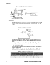
... DCDA GND 5 6 CTSA RTSA 9 21 GND RXA DCDA DTRA +5VDC TXA CTSA RTSA RXB TXB 12 11 CON4 TXB GND RXB Test Bed Connectors The CoBox-Micro test bed has four connectors: CON1 (Serial Port 1 or Channel 1), CON2 (TTL Interface), CON4 (Serial Port 2 or Channel 2), and CON3, which is ... Embedded Integration Kit Integration Guide b. This RS232 level serial interface is compatible with a DB9F connector. Note: CON3 is a 5VDC power supply connector. CoBox-Micro Figure 2-7. Table 2-3. The DB9 connector is implemented with most PC serial interface ports using a straight through cable.
... DCDA GND 5 6 CTSA RTSA 9 21 GND RXA DCDA DTRA +5VDC TXA CTSA RTSA RXB TXB 12 11 CON4 TXB GND RXB Test Bed Connectors The CoBox-Micro test bed has four connectors: CON1 (Serial Port 1 or Channel 1), CON2 (TTL Interface), CON4 (Serial Port 2 or Channel 2), and CON3, which is ... Embedded Integration Kit Integration Guide b. This RS232 level serial interface is compatible with a DB9F connector. Note: CON3 is a 5VDC power supply connector. CoBox-Micro Figure 2-7. Table 2-3. The DB9 connector is implemented with most PC serial interface ports using a straight through cable.

Embedded Integration Kit (EIK) - Integration Guide
Page 14
... Table 2-4. S/N:7401362 CO-E1-11AA 00-20-4A-74-05-52 Rev. CoBox-Micro Technical Specifications Category Memory Serial Flash Serial Interface Board Dimensions Weight Temperature Protocols Supported Network Interface Data Rates Serial Line Formats Modem ... device. C12 Made in combination with Channel 1) Network Link (Green) Ethernet: Version 2.0/IEEE 802.3 5VDC (±5%) regulated @ 200mA Product Information Label The CoBox-Micro ships with a product information label that can be affixed to as hardware address or MAC address). Through-hole plated pins, DIL Height: 1.575in (40.00...
... Table 2-4. S/N:7401362 CO-E1-11AA 00-20-4A-74-05-52 Rev. CoBox-Micro Technical Specifications Category Memory Serial Flash Serial Interface Board Dimensions Weight Temperature Protocols Supported Network Interface Data Rates Serial Line Formats Modem ... device. C12 Made in combination with Channel 1) Network Link (Green) Ethernet: Version 2.0/IEEE 802.3 5VDC (±5%) regulated @ 200mA Product Information Label The CoBox-Micro ships with a product information label that can be affixed to as hardware address or MAC address). Through-hole plated pins, DIL Height: 1.575in (40.00...

Embedded Integration Kit (EIK) - Integration Guide
Page 24
...Dimensions The following drawing is accomplished via TTL connectors, which make it easy to a PCB board. O 3.0 (0.118) 4x Figure 4-1. The CoBox-Mini also supports a variety of user-configurable options such as buffer control and packetization, which include transmit, receive, and full handshaking. Both the.... The serial interface is a top view of the CoBox-Mini. Note: This manual documents the present version (Rev 2) of the CoBox-Mini. The CoBox-Mini requires 5 volts DC of regulated power with maximum current of the CoBox-Mini's interface pins can be specified to fit your ...
...Dimensions The following drawing is accomplished via TTL connectors, which make it easy to a PCB board. O 3.0 (0.118) 4x Figure 4-1. The CoBox-Mini also supports a variety of user-configurable options such as buffer control and packetization, which include transmit, receive, and full handshaking. Both the.... The serial interface is a top view of the CoBox-Mini. Note: This manual documents the present version (Rev 2) of the CoBox-Mini. The CoBox-Mini requires 5 volts DC of regulated power with maximum current of the CoBox-Mini's interface pins can be specified to fit your ...

Embedded Integration Kit (EIK) - Integration Guide
Page 25
...length of 5.46 mm or 6.76 mm ‹ Bottom mounted, length of 5.46 mm or 6.76 mm Contact Lantronix or visit our Web site (www.lantronix.com) for a listing of ordering, each connector can be specified with the following table for information about ordering device ...servers with various connector configurations. Table 4-1. CoBox-Mini Connectors The CoBox-Mini has four connectors: ‹ TTL serial port (CON1) ‹ AUI ...
...length of 5.46 mm or 6.76 mm ‹ Bottom mounted, length of 5.46 mm or 6.76 mm Contact Lantronix or visit our Web site (www.lantronix.com) for a listing of ordering, each connector can be specified with the following table for information about ordering device ...servers with various connector configurations. Table 4-1. CoBox-Mini Connectors The CoBox-Mini has four connectors: ‹ TTL serial port (CON1) ‹ AUI ...

Embedded Integration Kit (EIK) - Integration Guide
Page 26
... 900-226 on CD ‹ Embedded Integration Kit Integration Guide, 900-316 on CD The test bed allows software engineers to drive LEDs. CoBox-Mini LED Signals Signal Description SerialPort (Channel) 1 Status SerialPort (Channel) 2 Status Diagnostic Network Link Status +5VDC +5VDC Signal Pin CON1... Link LED Test Bed The evaluation kit contains the following table for their product is complete. See the following items: ‹ Carrier Board ‹ CoBox-Mini Board ‹ +12VDC, 0.8A, International Power Supply with Full Handshaking 8 DTRB (output) 9 DCDB (input) 10 RTSB (output) B ...
... 900-226 on CD ‹ Embedded Integration Kit Integration Guide, 900-316 on CD The test bed allows software engineers to drive LEDs. CoBox-Mini LED Signals Signal Description SerialPort (Channel) 1 Status SerialPort (Channel) 2 Status Diagnostic Network Link Status +5VDC +5VDC Signal Pin CON1... Link LED Test Bed The evaluation kit contains the following table for their product is complete. See the following items: ‹ Carrier Board ‹ CoBox-Mini Board ‹ +12VDC, 0.8A, International Power Supply with Full Handshaking 8 DTRB (output) 9 DCDB (input) 10 RTSB (output) B ...

Embedded Integration Kit (EIK) - Integration Guide
Page 27
CoBox-Mini Carrier Board 96 5 1 96 DB-9M 5 1 CON1 PWR CON7 CH1 CON8 CH2 1 10 Reset Switch LED1 (Green) LED2 (Yellow) LED3 (Red) 1 10 1 6 7 1 CON4 1 8 LED4 (Link) LED5 (100MBit) Test Bed Connectors The CoBox-Mini test bed has five external connectors: ‹ CON4 (a 10Base-T RJ45 Connector) ‹ CON7 (Serial Port 1or Channel 1) ‹ CON8 (Serial Port 2 or Channel 2) ‹ CON1 (a 9-30 VDC power supply connector) (also accepts 9 -25 VAC) 4-4 Embedded Integration Kit Integration Guide CoBox-Mini Board Layout Figure 4-3.
CoBox-Mini Carrier Board 96 5 1 96 DB-9M 5 1 CON1 PWR CON7 CH1 CON8 CH2 1 10 Reset Switch LED1 (Green) LED2 (Yellow) LED3 (Red) 1 10 1 6 7 1 CON4 1 8 LED4 (Link) LED5 (100MBit) Test Bed Connectors The CoBox-Mini test bed has five external connectors: ‹ CON4 (a 10Base-T RJ45 Connector) ‹ CON7 (Serial Port 1or Channel 1) ‹ CON8 (Serial Port 2 or Channel 2) ‹ CON1 (a 9-30 VDC power supply connector) (also accepts 9 -25 VAC) 4-4 Embedded Integration Kit Integration Guide CoBox-Mini Board Layout Figure 4-3.

Embedded Integration Kit (EIK) - Integration Guide
Page 28
... indicate Channel 1 is connected to indicate Channel 2 is idle. Embedded Integration Kit Integration Guide 4-5 Note: CON1 is also designated as B. CoBox-Mini Pinout Configurations 1 8 CON4 (RJ45) 1 - TX+ 2 - Lights solid yellow to the network and active. Blinks yellow to ... 1 is also designated as A. TX3 - RX- LED 1 2 Description SerialPort (Channel) 1 Status SerialPort (Channel) 2 Status Table 4-4. CoBox-Mini Table 4-3. CoBox-Mini Test Bed Connectors CON4 10Base-T CON7 Serial Port CON8 Serial Port (RJ45) (Channel) 1(Note A) (Channel) 2(Note B) Pin Signal...
... indicate Channel 1 is connected to indicate Channel 2 is idle. Embedded Integration Kit Integration Guide 4-5 Note: CON1 is also designated as B. CoBox-Mini Pinout Configurations 1 8 CON4 (RJ45) 1 - TX+ 2 - Lights solid yellow to the network and active. Blinks yellow to ... 1 is also designated as A. TX3 - RX- LED 1 2 Description SerialPort (Channel) 1 Status SerialPort (Channel) 2 Status Table 4-4. CoBox-Mini Table 4-3. CoBox-Mini Test Bed Connectors CON4 10Base-T CON7 Serial Port CON8 Serial Port (RJ45) (Channel) 1(Note A) (Channel) 2(Note B) Pin Signal...

Embedded Integration Kit (EIK) - Integration Guide
Page 29
... 1 (solid Green = idle, blink = active) Channel 2 (solid Yellow = idle, blink = active) Diagnostics (Red, in combination with Channel 1) Network Link (Green) 4-6 Embedded Integration Kit Integration Guide CoBox-Mini LED Description Location 3 Diagnostics CON 1, Pin 9 4 Network Link Status *non-fatal error CON 3, Pin 6 LED Functions Blinks or lights solid red in combination with...
... 1 (solid Green = idle, blink = active) Channel 2 (solid Yellow = idle, blink = active) Diagnostics (Red, in combination with Channel 1) Network Link (Green) 4-6 Embedded Integration Kit Integration Guide CoBox-Mini LED Description Location 3 Diagnostics CON 1, Pin 9 4 Network Link Status *non-fatal error CON 3, Pin 6 LED Functions Blinks or lights solid red in combination with...